Owner's Manual (English)
Page 2
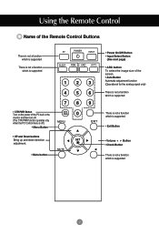
... the screen. • Auto Button Automatic adjustment function (Operational for the analog signal only) There is not a function which is supported There is not a function which is supported • Exit Button • Volume Button • Check Button * There is not a function which is off . (The CTR.PWR function operates only when the PC Control menu is supported 2 PWR 0 • Power On/Off Button • Input Select Button (See next page) • ARC button...
... the screen. • Auto Button Automatic adjustment function (Operational for the analog signal only) There is not a function which is supported There is not a function which is supported • Exit Button • Volume Button • Check Button * There is not a function which is off . (The CTR.PWR function operates only when the PC Control menu is supported 2 PWR 0 • Power On/Off Button • Input Select Button (See next page) • ARC button...
Owner's Manual (English)
Page 4
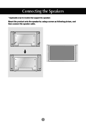
Connecting the Speakers * Applicable only for models that support the speakers Mount the product onto the speaker by using a screw as following picture, and then connect the speaker cable. 4
Connecting the Speakers * Applicable only for models that support the speakers Mount the product onto the speaker by using a screw as following picture, and then connect the speaker cable. 4
Owner's Manual (English)
Page 5
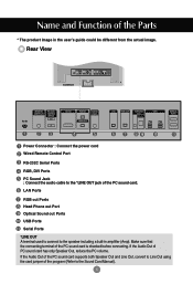
... OUT LAN RGB OUT H/PHONE USB OUT SP/DIF SERLAL PORT Power Connector : Connect the power cord Wired Remote Control Port RS-232C Serial Ports RGB, DVI Ports PC Sound Jack : Connect the audio cable to the speaker including a built-in the user's guide could be different from the actual image. LAN Ports RGB out Ports Head Phone out Port Optical Sound out Ports USB Ports Serlal Ports *LINE OUT A terminal used to connect to the *LINE OUT jack of...
... OUT LAN RGB OUT H/PHONE USB OUT SP/DIF SERLAL PORT Power Connector : Connect the power cord Wired Remote Control Port RS-232C Serial Ports RGB, DVI Ports PC Sound Jack : Connect the audio cable to the speaker including a built-in the user's guide could be different from the actual image. LAN Ports RGB out Ports Head Phone out Port Optical Sound out Ports USB Ports Serlal Ports *LINE OUT A terminal used to connect to the *LINE OUT jack of...
Owner's Manual (English)
Page 6
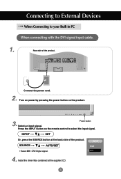
Rear side of the product. SOURCE AUTO/SET • Select DVI : DVI Digital signal. Install the driver files contained at the back side of the product. REMOTE CONTROL IN RS-232C (CONTROL& SERVICE) OUT IN DVI IN RGB IN AUDIO (RGB/DVI) RGB OUT LAN RGB OUT H/PHONE USB OUT SP/DIF SERLAL PORT Connect the power cord. 2. Power button Press the INPUT button on the product. SOURCE AUTO/SET ON/OFF 3. Select an input signal. Turn on power by...
Rear side of the product. SOURCE AUTO/SET • Select DVI : DVI Digital signal. Install the driver files contained at the back side of the product. REMOTE CONTROL IN RS-232C (CONTROL& SERVICE) OUT IN DVI IN RGB IN AUDIO (RGB/DVI) RGB OUT LAN RGB OUT H/PHONE USB OUT SP/DIF SERLAL PORT Connect the power cord. 2. Power button Press the INPUT button on the product. SOURCE AUTO/SET ON/OFF 3. Select an input signal. Turn on power by...
Owner's Manual (English)
Page 7
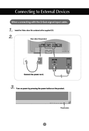
Connecting to External Devices When connecting with the D-Sub signal input cable. 1. Install the Video driver file contained at the supplied CD. 2. Rear side of the product. REMOTE CONTROL IN RS-232C (CONTROL& SERVICE) OUT IN DVI IN RGB IN AUDIO (RGB/DVI) RGB OUT LAN RGB OUT H/PHONE USB OUT SP/DIF SERLAL PORT RGB IN RGB OUT Connect the power cord. 3. Turn on power by pressing the power button on the product. SOURCE AUTO/SET ON/OFF Power button 7
Connecting to External Devices When connecting with the D-Sub signal input cable. 1. Install the Video driver file contained at the supplied CD. 2. Rear side of the product. REMOTE CONTROL IN RS-232C (CONTROL& SERVICE) OUT IN DVI IN RGB IN AUDIO (RGB/DVI) RGB OUT LAN RGB OUT H/PHONE USB OUT SP/DIF SERLAL PORT RGB IN RGB OUT Connect the power cord. 3. Turn on power by pressing the power button on the product. SOURCE AUTO/SET ON/OFF Power button 7

Owner's Manual (English)
Page 10
...-pin D-Sub analog signal. Press the INPUT button in a remote control to select the computer to use. • Directly connect to a grounded power outlet on the remote control to select the input signal. INPUT SET Or, press the SOURCE button at the back side of the mouse. 2 Select 'Clone Main with a ground wire. 10 Click 'Yes' button. 10. Press the INPUT button on the wall or a power bar with monitor' menu. 9. Connect the signal cables (DVI and...
...-pin D-Sub analog signal. Press the INPUT button in a remote control to select the computer to use. • Directly connect to a grounded power outlet on the remote control to select the input signal. INPUT SET Or, press the SOURCE button at the back side of the mouse. 2 Select 'Clone Main with a ground wire. 10 Click 'Yes' button. 10. Press the INPUT button on the wall or a power bar with monitor' menu. 9. Connect the signal cables (DVI and...
Owner's Manual (English)
Page 11
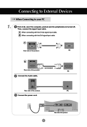
... Connect the Audio cable. Connect the power cord. 11 PC REMOTE CONTROL IN RS-232C (CONTROL& SERVICE) OUT IN DVI IN RGB IN AUDIO (RGB/DVI) RGB OUT LAN RGB OUT H/PHONE USB OUT SP/DIF SERLAL PORT Rear side of the product. Then, connect the signal input cable. Connecting to your PC First of all, see if the computer, product and the peripherals are turned off. When Connecting to External Devices...
... Connect the Audio cable. Connect the power cord. 11 PC REMOTE CONTROL IN RS-232C (CONTROL& SERVICE) OUT IN DVI IN RGB IN AUDIO (RGB/DVI) RGB OUT LAN RGB OUT H/PHONE USB OUT SP/DIF SERLAL PORT Rear side of the product. Then, connect the signal input cable. Connecting to your PC First of all, see if the computer, product and the peripherals are turned off. When Connecting to External Devices...
Owner's Manual (English)
Page 12
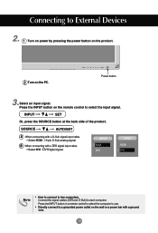
... the wall or a power bar with a ground wire. 12 Press the INPUT button in a remote control to select the computer to use. • Directly connect to each computer. B When connecting with a D-Sub signal input cable. • Select RGB : 15-pin D-Sub analog signal. SOURCE AUTO/SET A When connecting with a DVI signal input cable. • Select DVI : DVI Digital signal. INPUT RGB DVI INPUT RGB DVI Note • How to connect to External Devices 2. 1 Turn on power by pressing the power button...
... the wall or a power bar with a ground wire. 12 Press the INPUT button in a remote control to select the computer to use. • Directly connect to each computer. B When connecting with a D-Sub signal input cable. • Select RGB : 15-pin D-Sub analog signal. SOURCE AUTO/SET A When connecting with a DVI signal input cable. • Select DVI : DVI Digital signal. INPUT RGB DVI INPUT RGB DVI Note • How to connect to External Devices 2. 1 Turn on power by pressing the power button...
Owner's Manual (English)
Page 15
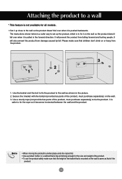
... Use the braket and the bolt to fix the product to the wall as parts of the product, must purchase separately) on the wall. 3. Use a sturdy rope (not provided as shown in the forward direction. It is pulled in the picture. 2. The instructions shown below is a safer way to set up close to the wall so...of the braket that is mounted on the wall is pushed backwards. Secure the bracket with the bolt(not provided as that of the product. 15 Attaching the product to a wall * This feature is not available for the size and weight of the product. • To use the product safely make ...
... Use the braket and the bolt to fix the product to the wall as parts of the product, must purchase separately) on the wall. 3. Use a sturdy rope (not provided as shown in the forward direction. It is pulled in the picture. 2. The instructions shown below is a safer way to set up close to the wall so...of the braket that is mounted on the wall is pushed backwards. Secure the bracket with the bolt(not provided as that of the product. 15 Attaching the product to a wall * This feature is not available for the size and weight of the product. • To use the product safely make ...
Owner's Manual (English)
Page 16
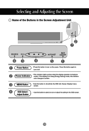
... the Buttons in the Screen Adjustment Unit SOURCE SOURCE AUTO/SET ON/OFF AUTO/SET ON/OFF Power Button • Press this button to select an icon or adjust the setting in sleep (Energy Saving) mode, this indicator color changes to show/hide the OSD (On Screen Display) menu screen. Power Indicator • This Indicator lights up blue when the display operates normally(on the power. OSD Select / Adjust Button • Use this button again to turn on mode). Press this button to turn it...
... the Buttons in the Screen Adjustment Unit SOURCE SOURCE AUTO/SET ON/OFF AUTO/SET ON/OFF Power Button • Press this button to select an icon or adjust the setting in sleep (Energy Saving) mode, this indicator color changes to show/hide the OSD (On Screen Display) menu screen. Power Indicator • This Indicator lights up blue when the display operates normally(on the power. OSD Select / Adjust Button • Use this button again to turn on mode). Press this button to turn it...

Owner's Manual (English)
Page 17
... that receives the signal from the remote control. 17 Selecting and Adjusting the Screen Name of the Buttons in the Screen Adjustment Unit AUTO/SET Button If the resolution is 1360X768 (RGB Mode) Auto in progress If the resolution is not 1360X768 (RGB Mode) Auto in progress For optimal display Change resolution to 1360 X 768 SOURCE Button • Select the input signal DVI (Digital signal) RGB(Analog signal) Digital signal and Analogue signal can't be outputted at the same time so when transferring the source connect...
... that receives the signal from the remote control. 17 Selecting and Adjusting the Screen Name of the Buttons in the Screen Adjustment Unit AUTO/SET Button If the resolution is 1360X768 (RGB Mode) Auto in progress If the resolution is not 1360X768 (RGB Mode) Auto in progress For optimal display Change resolution to 1360 X 768 SOURCE Button • Select the input signal DVI (Digital signal) RGB(Analog signal) Digital signal and Analogue signal can't be outputted at the same time so when transferring the source connect...

Owner's Manual (English)
Page 19
Press the AUTO/SET button (AUTO button in a remote Control) in the OSD menu. If adjustment is not 1360X768 Auto in progress If the resolution is not satisfactory, you want to adjust Select a Adjust the status menu icon Save Exit from the adjustment menu screen. • Use the remote control to adjust the OSD screen. 2 To access a control, use the Buttons. 3 When the icon you need to adjust the screen display when connecting the product to a new computer or changing the mode. Refer to...
Press the AUTO/SET button (AUTO button in a remote Control) in the OSD menu. If adjustment is not 1360X768 Auto in progress If the resolution is not satisfactory, you want to adjust Select a Adjust the status menu icon Save Exit from the adjustment menu screen. • Use the remote control to adjust the OSD screen. 2 To access a control, use the Buttons. 3 When the icon you need to adjust the screen display when connecting the product to a new computer or changing the mode. Refer to...
Owner's Manual (English)
Page 22
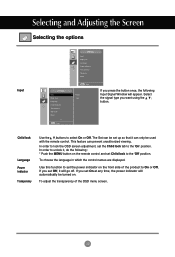
... displayed. To adjust the transparency of the product to the 'On' position. Reset Child lock Language Power indicator Transparency Use the buttons to unlock it can prevent unauthorized viewing. If you set Off, it will appear. Select the signal type you press the button once, the following : * Push the MENU button on the front side of the OSD menu screen. 22 Selecting and Adjusting the Screen Selecting the options Input Reset...
... displayed. To adjust the transparency of the product to the 'On' position. Reset Child lock Language Power indicator Transparency Use the buttons to unlock it can prevent unauthorized viewing. If you set Off, it will appear. Select the signal type you press the button once, the following : * Push the MENU button on the front side of the OSD menu screen. 22 Selecting and Adjusting the Screen Selecting the options Input Reset...

Owner's Manual (English)
Page 25
... factory default. If you set the Logo Display Lamp on or off both the monitor and the built-in the monitor. Off : Turn on/off the built-in PC only. * How to turn on the front side of the product to individually control each product when several ID products are connected for the A type) at the remote control. 25 Logo Light Use this function to reset...
... factory default. If you set the Logo Display Lamp on or off both the monitor and the built-in the monitor. Off : Turn on/off the built-in PC only. * How to turn on the front side of the product to individually control each product when several ID products are connected for the A type) at the remote control. 25 Logo Light Use this function to reset...
Owner's Manual (English)
Page 27
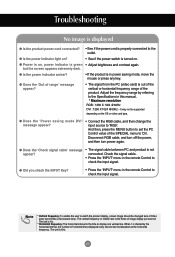
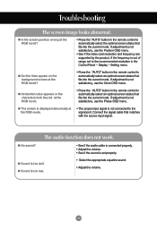
... power switch is the times of horizontal lines displayed every second can be supported depending on , power indicator is the time to check the input signal. but the screen appears extremely dark. Adjust the frequency range by the horizontal interval, the number of image display per second. G Does the 'Power saving mode DVI' message appear? • Connect the RGB cable, and then change the input source to the Specifications in the remote Control...
... power switch is the times of horizontal lines displayed every second can be supported depending on , power indicator is the time to check the input signal. but the screen appears extremely dark. Adjust the frequency range by the horizontal interval, the number of image display per second. G Does the 'Power saving mode DVI' message appear? • Connect the RGB cable, and then change the input source to the Specifications in the remote Control...
Owner's Manual (English)
Page 28
... audio cable is connected properly. • Adjust the volume. • See if the sound is not connected to automatically select the optimal screen status that matches with the source input signal. G Do thin lines appear on the background screen at the RGB mode. • The proper input signal is set to the recommended resolution in the remote control to the signal port. G The screen is displayed abnormally at the RGB mode? • Press the "AUTO" button...
... audio cable is connected properly. • Adjust the volume. • See if the sound is not connected to automatically select the optimal screen status that matches with the source input signal. G Do thin lines appear on the background screen at the RGB mode. • The proper input signal is set to the recommended resolution in the remote control to the signal port. G The screen is displayed abnormally at the RGB mode? • Press the "AUTO" button...

Owner's Manual (English)
Page 29
Settings - G The 'Child lock on the product. G After-image appears when the product is abnormal. Display - G Do black spots appear on the screen, which can be damaged quickly. Screen color is turned off. • If you use a fixed image for a long time, the pixels may appear on the screen? • Several pixels (red, green, white or black color) may be attributable to the unique characteristics of the LCD panel. After-image...
Settings - G The 'Child lock on the product. G After-image appears when the product is abnormal. Display - G Do black spots appear on the screen, which can be damaged quickly. Screen color is turned off. • If you use a fixed image for a long time, the pixels may appear on the screen? • Several pixels (red, green, white or black color) may be attributable to the unique characteristics of the LCD panel. After-image...
Owner's Manual (English)
Page 30
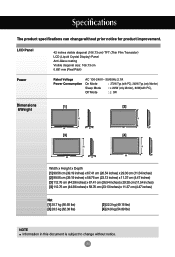
LCD Panel Power 42 inches visible diagonal (106.73 cm) TFT (Thin Film Transistor) LCD (Liquid Crystal Display) Panel Anti-Glare coating Visible diagonal size: 106.73 cm 0.681 mm (Pixel Pitch) Rated Voltage Power Consumption AC 100-240V~ 50/60Hz 2.7A On Mode : 270W Typ.(with PC), 240W Typ.(only Monitor) Sleep Mode : ≤ 20W (only Monitor), 60W(with PC), Off Mode : ≤ 5W Dimensions &Weight [1] [2] H W D [3] H W D [4] H W D H W D Width x Height...
LCD Panel Power 42 inches visible diagonal (106.73 cm) TFT (Thin Film Transistor) LCD (Liquid Crystal Display) Panel Anti-Glare coating Visible diagonal size: 106.73 cm 0.681 mm (Pixel Pitch) Rated Voltage Power Consumption AC 100-240V~ 50/60Hz 2.7A On Mode : 270W Typ.(with PC), 240W Typ.(only Monitor) Sleep Mode : ≤ 20W (only Monitor), 60W(with PC), Off Mode : ≤ 5W Dimensions &Weight [1] [2] H W D [3] H W D [4] H W D H W D Width x Height...
Owner's Manual (English)
Page 35
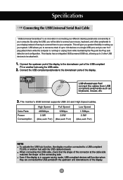
... cables from USB compliant peripherals-such as keyboard, mouse, etc 3. USB allows you can "hot" plug (attach them while the computer is running) or unplug them to 120 devices on a single USB port; The monitor's USB terminal supports USB 2.0 and High Speed cables. By using the USB cable. 2. Connect the USB compliant peripherals to a USB compliant PC(OS) or another hub using the USB, you greater flexibility in a power saving mode, USB...
... cables from USB compliant peripherals-such as keyboard, mouse, etc 3. USB allows you can "hot" plug (attach them while the computer is running) or unplug them to 120 devices on a single USB port; The monitor's USB terminal supports USB 2.0 and High Speed cables. By using the USB cable. 2. Connect the USB compliant peripherals to a USB compliant PC(OS) or another hub using the USB, you greater flexibility in a power saving mode, USB...
Owner's Manual (English)
Page 36
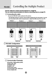
... PC. Connecting the cable Connect the RS-232C cable as shown in the picture. * The RS-232C protocol is used for communication between the PC and product. You can turn the product on/off, select an input source or adjust the OSD menu from your PC. Product 1 Product 2 Product 3 Product 4 RS-232C (CONTROL& SERVICE) OUT IN RS-232C (CONTROL& SERVICE) OUT IN RS-232C (CONTROL& SERVICE) OUT...
... PC. Connecting the cable Connect the RS-232C cable as shown in the picture. * The RS-232C protocol is used for communication between the PC and product. You can turn the product on/off, select an input source or adjust the OSD menu from your PC. Product 1 Product 2 Product 3 Product 4 RS-232C (CONTROL& SERVICE) OUT IN RS-232C (CONTROL& SERVICE) OUT IN RS-232C (CONTROL& SERVICE) OUT...


