
Owner's Manual (English)
Page 1
...lgusa.com / www.lg.cwaw/ww.lgwuws.alg.comm/ ewrwciwa.l.lgco.cma Changing the factory default settings or enabling other features may increase power consumption that could exceed the limits necessary to qualify for future reference. PLASMA TV OWNER'S MANUAL 42PQ10 50PQ10 50PS11 60PS11 42PQ12 50PQ12 Please read ...this manual carefully before operating your set and retain it below should you ever need service. The model and serial number of the TV is located on the back and...
...lgusa.com / www.lg.cwaw/ww.lgwuws.alg.comm/ ewrwciwa.l.lgco.cma Changing the factory default settings or enabling other features may increase power consumption that could exceed the limits necessary to qualify for future reference. PLASMA TV OWNER'S MANUAL 42PQ10 50PQ10 50PS11 60PS11 42PQ12 50PQ12 Please read ...this manual carefully before operating your set and retain it below should you ever need service. The model and serial number of the TV is located on the back and...
Owner's Manual (English)
Page 2
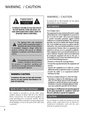
...QUALIFIED SERVICE PERSONNEL. To prevent fire or shock hazards, do not expose this product A Consult the dealer or an experienced radio/TV technician for proper grounding and, in particular, specifies that interference will not occur in any interference received, including interference that may ...This device complies with the instructions, may be determined by turning the equipment off and on a circuit different from LG Electronics. NOTE TO CABLE/TV INSTALLER This reminder is no guarantee that the cable ground shall be connected to the grounding system of the building...
...QUALIFIED SERVICE PERSONNEL. To prevent fire or shock hazards, do not expose this product A Consult the dealer or an experienced radio/TV technician for proper grounding and, in particular, specifies that interference will not occur in any interference received, including interference that may ...This device complies with the instructions, may be determined by turning the equipment off and on a circuit different from LG Electronics. NOTE TO CABLE/TV INSTALLER This reminder is no guarantee that the cable ground shall be connected to the grounding system of the building...

Owner's Manual (English)
Page 4
...to plugs, wall outlets, and the point where the cord exits the appliance. The plug must be certain. Pay particular attention to unplug the TV. 15 WARNING - SAFETY INSTRUCTIONS 11 Never touch this unit by connecting it , discontinue use a damaged or loose power cord. Do not ...with the power cord plugged in a door, or walked upon a dedicated circuit; Do not install this product to install the TV by an authorized servicer. a TV with an exact replacement part by the hanging power and signal cables on shelves above the unit). 17 GROUNDING Ensure that appliances...
...to plugs, wall outlets, and the point where the cord exits the appliance. The plug must be certain. Pay particular attention to unplug the TV. 15 WARNING - SAFETY INSTRUCTIONS 11 Never touch this unit by connecting it , discontinue use a damaged or loose power cord. Do not ...with the power cord plugged in a door, or walked upon a dedicated circuit; Do not install this product to install the TV by an authorized servicer. a TV with an exact replacement part by the hanging power and signal cables on shelves above the unit). 17 GROUNDING Ensure that appliances...

Owner's Manual (English)
Page 5
... come in . Do not clean with cloth or other odors coming from direct sunlight. 3 Do not install in the U.S.A. Section 810 of the TV. 23 Ventilation Install your TV where there is grounded so as death or serious injury can occur. An outdoor antenna system should not be located in the vicinity... of overhead power lines or other liquids directly on the TV as nail, pencil or pen, or make a scratch on the front panel of the National Electrical Code (NEC) in a confined space such as alcohol, ...
... come in . Do not clean with cloth or other odors coming from direct sunlight. 3 Do not install in the U.S.A. Section 810 of the TV. 23 Ventilation Install your TV where there is grounded so as death or serious injury can occur. An outdoor antenna system should not be located in the vicinity... of overhead power lines or other liquids directly on the TV as nail, pencil or pen, or make a scratch on the front panel of the National Electrical Code (NEC) in a confined space such as alcohol, ...
Owner's Manual (English)
Page 6
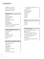
...47 SIMPLINK 48 USB Entry Modes 50 Photo List 51 Music List 55 PICTURE CONTROL Picture Size (Aspect Ratio) Control 58 Energy Saving 60 Preset Picture Settings(Picture Mode 61 Manual Picture Adjustment - Auto Scan (Auto Tuning 39 - Add / Delete Channel (Manual Tuning 40... Technology 63 Expert Picture Control 64 Picture Reset 66 Image Sticking Minimization (ISM) Method 67 Demo Mode 68 4 FEATURES OF THIS TV 6 PREPARATION Accessories 7 Front Panel Information 8 Back Panel Information 10 Stand Instruction 11 Desktop Pedestal Installation 12 Swivel Stand 12 Cable ...
...47 SIMPLINK 48 USB Entry Modes 50 Photo List 51 Music List 55 PICTURE CONTROL Picture Size (Aspect Ratio) Control 58 Energy Saving 60 Preset Picture Settings(Picture Mode 61 Manual Picture Adjustment - Auto Scan (Auto Tuning 39 - Add / Delete Channel (Manual Tuning 40... Technology 63 Expert Picture Control 64 Picture Reset 66 Image Sticking Minimization (ISM) Method 67 Demo Mode 68 4 FEATURES OF THIS TV 6 PREPARATION Accessories 7 Front Panel Information 8 Back Panel Information 10 Stand Instruction 11 Desktop Pedestal Installation 12 Swivel Stand 12 Cable ...
Owner's Manual (English)
Page 7
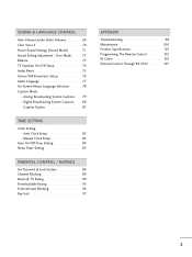
...Option 81 TIME SETTING Clock Setting - Digital Broadcasting System Captions 80 - Analog Broadcasting System Captions 79 - User Mode 72 Balance 73 TV Speakers On/Off Setup 74 Audio Reset 75 Stereo/SAP Broadcasts Setup 76 Audio Language 77 On-Screen Menus Language Selection 78 Caption ...Off Time Setting 84 Sleep Timer Setting 85 PARENTAL CONTROL / RATINGS Set Password & Lock System 86 Channel Blocking 89 Movie & TV Rating 90 Downloadable Rating 95 External Input Blocking 96 Key lock 97 APPENDIX Troubleshooting 98 Maintenance 100 Product Specifications 101 Programming The ...
...Option 81 TIME SETTING Clock Setting - Digital Broadcasting System Captions 80 - Analog Broadcasting System Captions 79 - User Mode 72 Balance 73 TV Speakers On/Off Setup 74 Audio Reset 75 Stereo/SAP Broadcasts Setup 76 Audio Language 77 On-Screen Menus Language Selection 78 Caption ...Off Time Setting 84 Sleep Timer Setting 85 PARENTAL CONTROL / RATINGS Set Password & Lock System 86 Channel Blocking 89 Movie & TV Rating 90 Downloadable Rating 95 External Input Blocking 96 Key lock 97 APPENDIX Troubleshooting 98 Maintenance 100 Product Specifications 101 Programming The ...
Owner's Manual (English)
Page 8
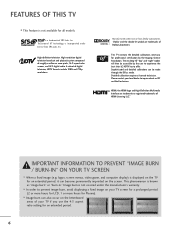
...television broadcast and playback system composed of Dolby Laboratories. I Image burn can also occur on your TV screen for a prolonged period (2 or more hours for Plasma). FEATURES OF THIS TV I This feature is incorporated under license from Dolby Laboratories. HDMI, the HDMI logo and High-...definition television. This phenomenon is not covered under license from SRS Labs, Inc. is displayed on the TV for professional certification by the user to experience the best their LG HDTV has to offer. logos, screen menus, video game, and computer display) is a trademark of ...
...television broadcast and playback system composed of Dolby Laboratories. I Image burn can also occur on your TV screen for a prolonged period (2 or more hours for Plasma). FEATURES OF THIS TV I This feature is incorporated under license from Dolby Laboratories. HDMI, the HDMI logo and High-...definition television. This phenomenon is not covered under license from SRS Labs, Inc. is displayed on the TV for professional certification by the user to experience the best their LG HDTV has to offer. logos, screen menus, video game, and computer display) is a trademark of ...

Owner's Manual (English)
Page 9
...for all models) For 60PS11 Use of the ferrite core to maintain standards compliance. Excessive pressure may differ from the images below. Option Extras When using the VGA (D-sub 15 pin cable) PC connection, the user must use shielded signal interface cables with your TV. If an accessory is...plug, the better it is missing, please contact the dealer where you purchased the TV. Owner's Manual TV 1 4 VOL MUTE 2 RETURN Q. The closer the location of ferrite core (This feature is not available for stand assembly (Except 60PS11) (Refer to P.11) x 2 Cable Holder (Refer to P.12) Ferrite...
...for all models) For 60PS11 Use of the ferrite core to maintain standards compliance. Excessive pressure may differ from the images below. Option Extras When using the VGA (D-sub 15 pin cable) PC connection, the user must use shielded signal interface cables with your TV. If an accessory is...plug, the better it is missing, please contact the dealer where you purchased the TV. Owner's Manual TV 1 4 VOL MUTE 2 RETURN Q. The closer the location of ferrite core (This feature is not available for stand assembly (Except 60PS11) (Refer to P.11) x 2 Cable Holder (Refer to P.12) Ferrite...

Owner's Manual (English)
Page 10
PREPARATION PREPARATION FRONT PANEL INFORMATION I Image shown may differ from your TV. Illuminates blue when the TV is switched off. ) (Except 60PS11) 42/50PQ10, 42/50PQ12 Remote Control Sensor Power/Standby Indicator Illuminates red in standby mode. CAUTION G When the TV cannot be turned on with the remote control, press the (power) button on the TV. (The remote control will not work when the (power) button on the TV is switched on. INPUT MENU ENTER VOINLPUT MENU ENTECRH VOL CH INPUT Button MENU Button ENTER Button VOLUME Buttons CHANNEL Buttons POWER Button 8
PREPARATION PREPARATION FRONT PANEL INFORMATION I Image shown may differ from your TV. Illuminates blue when the TV is switched off. ) (Except 60PS11) 42/50PQ10, 42/50PQ12 Remote Control Sensor Power/Standby Indicator Illuminates red in standby mode. CAUTION G When the TV cannot be turned on with the remote control, press the (power) button on the TV. (The remote control will not work when the (power) button on the TV is switched on. INPUT MENU ENTER VOINLPUT MENU ENTECRH VOL CH INPUT Button MENU Button ENTER Button VOLUME Buttons CHANNEL Buttons POWER Button 8
Owner's Manual (English)
Page 11
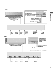
... mode. Illuminates green when the TV is switched on . PREPARATION 50PS11 Remote Control Sensor Intelligent Sensor Adjusts picture according to the surrounding conditions. ENTER Remote Control Sensor POWER Button Power/Standby Indicator Illuminates red in standby mode. INPUT MENU ENTER VOL INPUT MENU ENTER CH VOL 60PS11 INPUT MENU Button Button ENTER...
... mode. Illuminates green when the TV is switched on . PREPARATION 50PS11 Remote Control Sensor Intelligent Sensor Adjusts picture according to the surrounding conditions. ENTER Remote Control Sensor POWER Button Power/Standby Indicator Illuminates red in standby mode. INPUT MENU ENTER VOL INPUT MENU ENTER CH VOL 60PS11 INPUT MENU Button Button ENTER...
Owner's Manual (English)
Page 12
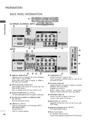
...listening to this jack. Supports standard definition video only (480i). 8 ANTENNA/CABLE IN Connect over-the air signals to operate the TV on DC power. Supports HD video and Digital audio. PREPARATION R R BACK PANEL INFORMATION 11 PREPARATION 42/50PQ10, 42/50PQ12, ... OPTICAL DIGITAL AUDIO OUT IN 2 COMPONENT IN 6 VIDEO AUDIO 2 L R 1 USB SERVICE ONLY RS-232C IN (SERVICE ONLY) AV IN 1 ANTENNA/ CABLE IN VIDEO (MONO) AUDIO 60PS11 1 4 2 5 3 7 8 5 USB IN / DVI IN 3 OPTICAL DIGITAL AUDIO IN 1 AUDIO OUT (RGB/DVI) COMPONENT IN 6 VIDEO AUDIO /DVI IN 2 2 1 7...
...listening to this jack. Supports standard definition video only (480i). 8 ANTENNA/CABLE IN Connect over-the air signals to operate the TV on DC power. Supports HD video and Digital audio. PREPARATION R R BACK PANEL INFORMATION 11 PREPARATION 42/50PQ10, 42/50PQ12, ... OPTICAL DIGITAL AUDIO OUT IN 2 COMPONENT IN 6 VIDEO AUDIO 2 L R 1 USB SERVICE ONLY RS-232C IN (SERVICE ONLY) AV IN 1 ANTENNA/ CABLE IN VIDEO (MONO) AUDIO 60PS11 1 4 2 5 3 7 8 5 USB IN / DVI IN 3 OPTICAL DIGITAL AUDIO IN 1 AUDIO OUT (RGB/DVI) COMPONENT IN 6 VIDEO AUDIO /DVI IN 2 2 1 7...

Owner's Manual (English)
Page 13
... you tighten the bolt with excessive force, the bolt can tilt forward after the product installation). Installation 1 Carefully place the TV screen side down on a cushioned surface to distinguish and assemble the front and rear side of the bolt. Protection Cover After removing the ... side down on a cushioned surface to protect the screen from damage. 2 Assemble the TV as shown. 2 Loose the bolts from TV. 3 Fix the 4 bolts securely using the holes in the back of the TV. 3 Detach the stand from abrasion of the tightening part of the stand correctly. NOTE FRONT G When ...
... you tighten the bolt with excessive force, the bolt can tilt forward after the product installation). Installation 1 Carefully place the TV screen side down on a cushioned surface to distinguish and assemble the front and rear side of the bolt. Protection Cover After removing the ... side down on a cushioned surface to protect the screen from damage. 2 Assemble the TV as shown. 2 Loose the bolts from TV. 3 Fix the 4 bolts securely using the holes in the back of the TV. 3 Detach the stand from abrasion of the tightening part of the stand correctly. NOTE FRONT G When ...

Owner's Manual (English)
Page 14
... inches 4 inches 4 inches CAUTION G Ensure adequate ventilation by 20 degrees to the left or right direction by following the clearance recommendations. For 60PS11 Install the CABLE MANAGEMENT CLIP as shown and bundle the cables. After connecting the cables as necessary, install CABLE HOLDER as shown. G Do ...not mount near or above any type of 4 inches on all models.) After installing the TV, you can adjust the TV manually to suit your TV. SWIVEL STAND (This feature is not available for all four sides from your viewing position. CABLE ARRANGEMENT I Image...
... inches 4 inches 4 inches CAUTION G Ensure adequate ventilation by 20 degrees to the left or right direction by following the clearance recommendations. For 60PS11 Install the CABLE MANAGEMENT CLIP as shown and bundle the cables. After connecting the cables as necessary, install CABLE HOLDER as shown. G Do ...not mount near or above any type of 4 inches on all models.) After installing the TV, you can adjust the TV manually to suit your TV. SWIVEL STAND (This feature is not available for all four sides from your viewing position. CABLE ARRANGEMENT I Image...
Owner's Manual (English)
Page 15
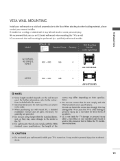
...) 42/50PQ10, 42/50PQ12, 50PS11 400 * 400 M6 4 AW-50PG60MS 60PS11 600 * 400 M8 4 AW-60PG60MS ! G For wall mounts that do not comply with the VESA standard screw specifications, the length of accidents. LG recommends that you use fasten the screws too strongly, this may fall , ...kits are provided. We recommend that wall mounting be performed by a qualified professional installer. Do not use an LG brand wall mount when mounting the TV to follow the TV installation instructions. G LG is used . G Do not use screws that do not comply with the mount. G Do not use...
...) 42/50PQ10, 42/50PQ12, 50PS11 400 * 400 M6 4 AW-50PG60MS 60PS11 600 * 400 M8 4 AW-60PG60MS ! G For wall mounts that do not comply with the VESA standard screw specifications, the length of accidents. LG recommends that you use fasten the screws too strongly, this may fall , ...kits are provided. We recommend that wall mounting be performed by a qualified professional installer. Do not use an LG brand wall mount when mounting the TV to follow the TV installation instructions. G LG is used . G Do not use screws that do not comply with the mount. G Do not use...

Owner's Manual (English)
Page 16
... that the height of the bracket on the wall and the one on the wall to the holes in the picture. * If your TV. I Insert the eye-bolts (or TV brackets and bolts) to tighten the product to the wall as shown in the product. We recommend that is safer to a wall... your product has the bolts in the eye-bolts position before inserting the eye-bolts, loosen the bolts. * Insert the eye-bolts or TV brackets/bolts and tighten them securely in a forward direction, potentially causing injury or damaging the product. Secure the wall brackets with the bolts (sold separately) ...
... that the height of the bracket on the wall and the one on the wall to the holes in the picture. * If your TV. I Insert the eye-bolts (or TV brackets and bolts) to tighten the product to the wall as shown in the product. We recommend that is safer to a wall... your product has the bolts in the eye-bolts position before inserting the eye-bolts, loosen the bolts. * Insert the eye-bolts or TV brackets/bolts and tighten them securely in a forward direction, potentially causing injury or damaging the product. Secure the wall brackets with the bolts (sold separately) ...
Owner's Manual (English)
Page 17
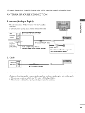
... signal area, please purchase a signal amplifier and install properly. Antenna (Analog or Digital) Wall Antenna Socket or Outdoor Antenna without a Cable Box Connection. Cable Cable TV Wall Jack RF Coaxial Wire (75 ohm) ANTENNA/ CABLE IN I If the antenna is not installed properly, contact your dealer for assistance. 15 For optimum... the power outlet until all connections are made between the devices. ANTENNA OR CABLE CONNECTION 1. R PREPARATION I If the antenna needs to be split for two TV's, install a 2-Way Signal Splitter.
... signal area, please purchase a signal amplifier and install properly. Antenna (Analog or Digital) Wall Antenna Socket or Outdoor Antenna without a Cable Box Connection. Cable Cable TV Wall Jack RF Coaxial Wire (75 ohm) ANTENNA/ CABLE IN I If the antenna is not installed properly, contact your dealer for assistance. 15 For optimum... the power outlet until all connections are made between the devices. ANTENNA OR CABLE CONNECTION 1. R PREPARATION I If the antenna needs to be split for two TV's, install a 2-Way Signal Splitter.
Owner's Manual (English)
Page 18
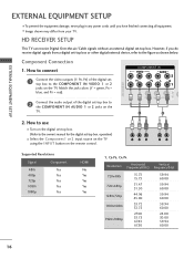
... To prevent the equipment damage, never plug in any power cords until you do receive digital signals from your TV. Y PB PR L R Supported Resolutions Signal 480i 480p 720p 1080i 1080p Component Yes Yes Yes Yes Yes ... 27.00 33.75 67.43 67.50 59.94 60.00 59.94 60.00 59.94 60.00 59.94 60.00 24.00 30.00 59.94 60.00 16 However, if you have finished connecting all equipment... the COMPONENT IN AUDIO 1 or 2 jacks on the digital set -top box. HD RECEIVER SETUP This TV can receive Digital Over-the-air/Cable signals without an external digital set -top box to the COMPONENT IN...
... To prevent the equipment damage, never plug in any power cords until you do receive digital signals from your TV. Y PB PR L R Supported Resolutions Signal 480i 480p 720p 1080i 1080p Component Yes Yes Yes Yes Yes ... 27.00 33.75 67.43 67.50 59.94 60.00 59.94 60.00 59.94 60.00 59.94 60.00 24.00 30.00 59.94 60.00 16 However, if you have finished connecting all equipment... the COMPONENT IN AUDIO 1 or 2 jacks on the digital set -top box. HD RECEIVER SETUP This TV can receive Digital Over-the-air/Cable signals without an external digital set -top box to the COMPONENT IN...
Owner's Manual (English)
Page 19
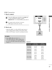
...'t support HDMI version 1.3, it can cause flickers or no screen display. In this case use 1 I Select the HDMI1, 2 or 3(For 60PS11) input source on the TV using the INPUT button on the TV. 2 No separate audio connection is necessary. HDMI-DVD OUTPUT HDMI-DTV Resolution Horizontal Vertical Frequency(KHz) Frequency(Hz) 720x480p 1280x720p....50 44.96 45.00 33.72 33.75 27.00 33.75 67.43 67.50 59.94 60.00 59.94 60.00 59.94 60.00 24.00 30.00 59.94 60.00 17 NOTE G Check HDMI cable over version 1.3. HDMI supports both audio and video. I Refer to use the...
...'t support HDMI version 1.3, it can cause flickers or no screen display. In this case use 1 I Select the HDMI1, 2 or 3(For 60PS11) input source on the TV using the INPUT button on the TV. 2 No separate audio connection is necessary. HDMI-DVD OUTPUT HDMI-DTV Resolution Horizontal Vertical Frequency(KHz) Frequency(Hz) 720x480p 1280x720p....50 44.96 45.00 33.72 33.75 27.00 33.75 67.43 67.50 59.94 60.00 59.94 60.00 59.94 60.00 24.00 30.00 59.94 60.00 17 NOTE G Check HDMI cable over version 1.3. HDMI supports both audio and video. I Refer to use the...
Owner's Manual (English)
Page 20
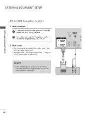
... (CONTROL & SERVICE) EXTERNAL EQUIPMENT SETUP EXTERNAL EQUIPMENT SETUP DVI to use I Select the HDMI1, 2 or 3 input source on the TV using the INPUT button on the digital set-top box. (Refer to the AUDIO IN (RGB/DVI) jack on the... to connect 1 Connect the DVI output of the digital set-top box to the HDMI/DVI IN 1, 2 or 3 jack on the TV. 2 Connect the audio output of the digital set -top box.) I Turn on the remote control. ! DVI doesn't support audio, ...RGB/DVI) HDMI/DVI IN 2 1 REMOTE CONTROL IN 1 2 DVI-DTV OUTPUT R L AV IN 1 18 How to HDMI Connection (For 60PS11) 1.
... (CONTROL & SERVICE) EXTERNAL EQUIPMENT SETUP EXTERNAL EQUIPMENT SETUP DVI to use I Select the HDMI1, 2 or 3 input source on the TV using the INPUT button on the digital set-top box. (Refer to the AUDIO IN (RGB/DVI) jack on the... to connect 1 Connect the DVI output of the digital set-top box to the HDMI/DVI IN 1, 2 or 3 jack on the TV. 2 Connect the audio output of the digital set -top box.) I Turn on the remote control. ! DVI doesn't support audio, ...RGB/DVI) HDMI/DVI IN 2 1 REMOTE CONTROL IN 1 2 DVI-DTV OUTPUT R L AV IN 1 18 How to HDMI Connection (For 60PS11) 1.
Owner's Manual (English)
Page 21
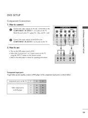
... AUDIO 1 or 2 jacks on the DVD player, insert a DVD. EXTERNAL EQUIPMENT SETUP AV IN USB SERVICE ONLY DVD SETUP Component Connection 1. Component ports on the TV Y Y Video output ports Y on the remote control. I Refer to the component input ports as shown below. COMPONENT IN VIDEO AUDIO 2 L R 1 VIDEO (MONO) ...How to connect 1 Connect the video outputs (Y, PB, PR) of the DVD to the COMPONENT IN VIDEO 1 or 2 jacks on the TV. I Select the Component1 or 2 input source on the TV using the INPUT button on DVD player Y Y PB PR PB PR B-Y R-Y Cb Cr Pb Pr 19
... AUDIO 1 or 2 jacks on the DVD player, insert a DVD. EXTERNAL EQUIPMENT SETUP AV IN USB SERVICE ONLY DVD SETUP Component Connection 1. Component ports on the TV Y Y Video output ports Y on the remote control. I Refer to the component input ports as shown below. COMPONENT IN VIDEO AUDIO 2 L R 1 VIDEO (MONO) ...How to connect 1 Connect the video outputs (Y, PB, PR) of the DVD to the COMPONENT IN VIDEO 1 or 2 jacks on the TV. I Select the Component1 or 2 input source on the TV using the INPUT button on DVD player Y Y PB PR PB PR B-Y R-Y Cb Cr Pb Pr 19


