
Owners Manual
Page 1
.... As an ENERGY STAR Partner LGE U. has determined that this information to your set . Record model number and serial number of power-saving guidelines issued by the U.S. LCD TV PLASMA TV OWNER'S MANUAL LCD TV MODELS 37LBSD 42LBSD 47LBSD S2LBSD 47LC7DF PLASMA TV MODELS SOPY3D SOPY3DF 60PY3D 60PY3DF Please read this manual carefully before operating your dealer...
.... As an ENERGY STAR Partner LGE U. has determined that this information to your set . Record model number and serial number of power-saving guidelines issued by the U.S. LCD TV PLASMA TV OWNER'S MANUAL LCD TV MODELS 37LBSD 42LBSD 47LBSD S2LBSD 47LC7DF PLASMA TV MODELS SOPY3D SOPY3DF 60PY3D 60PY3DF Please read this manual carefully before operating your dealer...
Owners Manual
Page 5
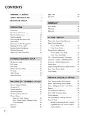
... SimpLink 42 4 Input Label 44 Key Lock 45 Entry Modes 46 Photo List 47 Music List 51 Picture Size (Aspect Ratio) Control 53 Preset Picture Settings - Picture Mode - Picture Mode - Preset 54 - Color Tone - Cinema 3:2 Pulldown Mode 59 Advanced - Analog Broadcasting System Captions ....... 74 - ...Advanced - Power Picture Mode 63 Front Display 64 Auto Volume Leveller (Auto Volume 65 Preset Sound Setting (Sound Mode 66 Sound Setting Adjustment - User Mode 67 Balance 68 TV Speakers On/Off Setup 69 Stereo/SAP Broadcasts Setup 70 Audio Language 71 On-Screen Menus Language ...
... SimpLink 42 4 Input Label 44 Key Lock 45 Entry Modes 46 Photo List 47 Music List 51 Picture Size (Aspect Ratio) Control 53 Preset Picture Settings - Picture Mode - Picture Mode - Preset 54 - Color Tone - Cinema 3:2 Pulldown Mode 59 Advanced - Analog Broadcasting System Captions ....... 74 - ...Advanced - Power Picture Mode 63 Front Display 64 Auto Volume Leveller (Auto Volume 65 Preset Sound Setting (Sound Mode 66 Sound Setting Adjustment - User Mode 67 Balance 68 TV Speakers On/Off Setup 69 Stereo/SAP Broadcasts Setup 70 Audio Language 71 On-Screen Menus Language ...

Owners Manual
Page 6
ManuaCl lockSetup 7.8... AutoClockSetup 7..7... - ClockSetting - Auto On/Off Time Setting 79 Sleep Time Setting 80 Auto Shut-off Setting 81 Set Password & Lock System 82 Channel Blocking 84 External Input Blocking 84 Movie & TV Rating 85 Troubleshooting 88 Maintenance 90 Product Specifications 91 Programming the Remote Control 93 IR Codes 97 External Control Through RS-232C 99 Open Source License 106 S
ManuaCl lockSetup 7.8... AutoClockSetup 7..7... - ClockSetting - Auto On/Off Time Setting 79 Sleep Time Setting 80 Auto Shut-off Setting 81 Set Password & Lock System 82 Channel Blocking 84 External Input Blocking 84 Movie & TV Rating 85 Troubleshooting 88 Maintenance 90 Product Specifications 91 Programming the Remote Control 93 IR Codes 97 External Control Through RS-232C 99 Open Source License 106 S
Owners Manual
Page 9
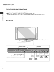
POWER Button MENU Button VOLUME (_,_) Buttons CHANNEL (T,A) Buttons 8 PREPARATION FRONT PANELINFORMATION ,,,IHere shown may be somewhat different from your product, use it). _o rrl _o © z Plasma TV Model Program Display Remote Control Sensor Touch Pad llluminates Power/Sta nd by Indicator llluminates red in standby mode. white when the set is included with your TV. ""_NOTE: If your product has a protection tape attached, remove the tape. -O And then wipe the product with a cloth (If a polishing cloth is switched on.
POWER Button MENU Button VOLUME (_,_) Buttons CHANNEL (T,A) Buttons 8 PREPARATION FRONT PANELINFORMATION ,,,IHere shown may be somewhat different from your product, use it). _o rrl _o © z Plasma TV Model Program Display Remote Control Sensor Touch Pad llluminates Power/Sta nd by Indicator llluminates red in standby mode. white when the set is included with your TV. ""_NOTE: If your product has a protection tape attached, remove the tape. -O And then wipe the product with a cloth (If a polishing cloth is switched on.
Owners Manual
Page 10
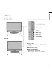
LCD TV Model 37/42/47/52LB5D 47LC7DF -O _o m _o © z (A,V)Buttons (_1,1_)Buttons --ENTER Bu_on Bu_on --INPUT --POWER Bu_on Bu_on Intelligent Eye Adjusts picture according to the surrounding conditions. llluminates green when the set is switched on. 9 Remote Control Sensor Power/Standby Indicator Illuminates red in standby mode.
LCD TV Model 37/42/47/52LB5D 47LC7DF -O _o m _o © z (A,V)Buttons (_1,1_)Buttons --ENTER Bu_on Bu_on --INPUT --POWER Bu_on Bu_on Intelligent Eye Adjusts picture according to the surrounding conditions. llluminates green when the set is switched on. 9 Remote Control Sensor Power/Standby Indicator Illuminates red in standby mode.
Owners Manual
Page 14
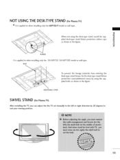
... the figure. plied desk-type stand fixture protection rubber caps _o as shown at the figure. ADDITIONAL COVER SWIVELSTAND (For Plasma TV) After installing the TV, you can adjust the the TV set manually to the left or right direction by using the desk-type stand, install the sup- To prevent the foreign materials... the desk-type stand fixture protection cover(additional cover) by 20 degrees to suit your viewing position. 13 NOT USING THE DESK-TYPESTAND (For Plasma TV) It is applied to when installing only the 50/60PY3D, BOLT 50/60PY3DF model as wall-type.
... the figure. plied desk-type stand fixture protection rubber caps _o as shown at the figure. ADDITIONAL COVER SWIVELSTAND (For Plasma TV) After installing the TV, you can adjust the the TV set manually to the left or right direction by using the desk-type stand, install the sup- To prevent the foreign materials... the desk-type stand fixture protection cover(additional cover) by 20 degrees to suit your viewing position. 13 NOT USING THE DESK-TYPESTAND (For Plasma TV) It is applied to when installing only the 50/60PY3D, BOLT 50/60PY3DF model as wall-type.
Owners Manual
Page 17
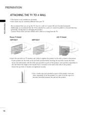
...,l_Use a sturdy rope (not provided as parts of the product, must purchase separately) to the holes in the picture. z Plasma TV Model 50PY3D/F 60PY3D/F LCD TV Model ii_i!i_i¸!iI_!Ii|!i|iIi|!l!I!||||| i_i_i_i'_iiiiliiilii!_iii_i!i!i_iiii!iiii_|i]|_i_i_ili!i!¸_|i|l|iii / iiill il_!i_ii __i !_iii! _ |...bolts (not provided as shown in the product. m We recommend that you set up the TV close to a wall so it becomes horizontal between the wall and the product. 16 PREPARATION ATTACHING THE TV TO A WALL ,,,IThis feature is not available for all models. ,,,iHere...
...,l_Use a sturdy rope (not provided as parts of the product, must purchase separately) to the holes in the picture. z Plasma TV Model 50PY3D/F 60PY3D/F LCD TV Model ii_i!i_i¸!iI_!Ii|!i|iIi|!l!I!||||| i_i_i_i'_iiiiliiilii!_iii_i!i!i_iiii!iiii_|i]|_i_i_ili!i!¸_|i|l|iii / iiill il_!i_ii __i !_iii! _ |...bolts (not provided as shown in the product. m We recommend that you set up the TV close to a wall so it becomes horizontal between the wall and the product. 16 PREPARATION ATTACHING THE TV TO A WALL ,,,IThis feature is not available for all models. ,,,iHere...
Owners Manual
Page 20
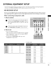
... x m O Connect the video outputs (Y, PB, PR) of the digital set _D z top box to use picture for LCD TV model. If connected to the figure as shown below. How to the COMPONENT IN VIDEO 1 jacks on > the set -top box.operation) Select Component 1 input source by using the INPUT button ... until you do receive digital signals from a digital set . 2. This part of the digital set-top box to z the COMPONENT IN AUDIO 1 jacks on the digital set-top box. (Referto the owner'smanualfor the digital set . HD RECEIVERSETUP This TV can receive Digital Over-the-air/Cable signals without ...
... x m O Connect the video outputs (Y, PB, PR) of the digital set _D z top box to use picture for LCD TV model. If connected to the figure as shown below. How to the COMPONENT IN VIDEO 1 jacks on > the set -top box.operation) Select Component 1 input source by using the INPUT button ... until you do receive digital signals from a digital set . 2. This part of the digital set-top box to z the COMPONENT IN AUDIO 1 jacks on the digital set-top box. (Referto the owner'smanualfor the digital set . HD RECEIVERSETUP This TV can receive Digital Over-the-air/Cable signals without ...
Owners Manual
Page 21
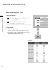
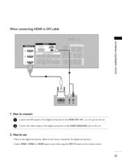
... 60.00 20 EXTERNALEQUIPMENT SETUP When connecting HDMI cable 1. How to connect m x O 2 oonrne3ct jatchke odnigtihtael sseett.-top box to the owner's manual for the digital set-top box.) c "O 01S_elect HDMI1, HDMI2 or HDMI3 input source with using the INPUT button on the digital...
... 60.00 20 EXTERNALEQUIPMENT SETUP When connecting HDMI cable 1. How to connect m x O 2 oonrne3ct jatchke odnigtihtael sseett.-top box to the owner's manual for the digital set-top box.) c "O 01S_elect HDMI1, HDMI2 or HDMI3 input source with using the INPUT button on the digital...
Owners Manual
Page 22
O Connect the audio output of the digital set-top box to DVI cable m x .-I m z m XZ) c "0 m z .-I m -4 C "0 1. When connecting HDMI to the HDMI/DVI IN1,2 or 3 jack on the remote control. 21 How to use 01T_urn on the digital set-top box. (Refer to the AUDIO (RGB/DVI) jack on the set -top box.) 01S_elect HDMII, HDMI2 or HDMI3 input source with using the INPUT button on the set. How to connect O Connect the DVI output of the digital set-top box to the owner's manual for the digital set . 2.
O Connect the audio output of the digital set-top box to DVI cable m x .-I m z m XZ) c "0 m z .-I m -4 C "0 1. When connecting HDMI to the HDMI/DVI IN1,2 or 3 jack on the remote control. 21 How to use 01T_urn on the digital set-top box. (Refer to the AUDIO (RGB/DVI) jack on the set -top box.) 01S_elect HDMII, HDMI2 or HDMI3 input source with using the INPUT button on the set. How to connect O Connect the DVI output of the digital set-top box to the owner's manual for the digital set . 2.
Owners Manual
Page 23
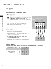
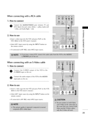
... To get better picture quality, connect a DVD player to the DVD player's manual for operating instructions. Component ports on the TV Video output ports on the set . How to use c "0 01_Turn on the DVD player, insert a DVD. 01_Select Component 1 input source by using the... INPUT button on the remote control. !!!! | 01_If connected to the "0 COMPONENT IN AUDIO1 jacks on the set . EXTERNALEQUIPMENT SETUP DVD SETUP When connecting Component cable 1. r_l Match the jack colors (Y = green, PB = blue, and PR = red). _o z r_l...
... To get better picture quality, connect a DVD player to the DVD player's manual for operating instructions. Component ports on the TV Video output ports on the set . How to use c "0 01_Turn on the DVD player, insert a DVD. 01_Select Component 1 input source by using the... INPUT button on the remote control. !!!! | 01_If connected to the "0 COMPONENT IN AUDIO1 jacks on the set . EXTERNALEQUIPMENT SETUP DVD SETUP When connecting Component cable 1. r_l Match the jack colors (Y = green, PB = blue, and PR = red). _o z r_l...
Owners Manual
Page 24
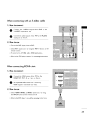
...manual for operating instructions. "O 01_Refer to connect O S-oVnInDeEctO the S-VIDEO input on the set . How to connect O onnect the HDMI output of the DVD to the AUDIO input jacks on the output set. When connecting HDMI cable 1. r_l z 01_Select AV1 input source by using the INPUT button ...on the remote control. 0_Refer to use 01_Select HDMI1, HDMI2, or HDMI3 input source by using the INPUT button on the set . How to the DVD player's manual for operating instructions. 23 of the DVD to the x r_l _o z e onnect the audio outputs...
...manual for operating instructions. "O 01_Refer to connect O S-oVnInDeEctO the S-VIDEO input on the set . How to connect O onnect the HDMI output of the DVD to the AUDIO input jacks on the output set. When connecting HDMI cable 1. r_l z 01_Select AV1 input source by using the INPUT button ...on the remote control. 0_Refer to use 01_Select HDMI1, HDMI2, or HDMI3 input source by using the INPUT button on the set . How to the DVD player's manual for operating instructions. 23 of the DVD to the x r_l _o z e onnect the audio outputs...
Owners Manual
Page 25
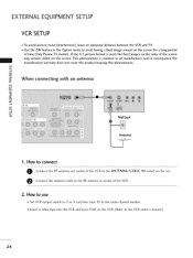
...to the ANTENNA/CABLE e Connect the antenna cable to the same channel number. 01_Insert a video tape into the VCR and press PLAY on the set. 2. This phenomenon is used; IN socket on the VCR. (Refer to avoid having a fixed image remain on the sides of the VCR.... z L_ r_l c "0 Wall Jack Antenna 1. EXTERNALEQUIPMENT SETUP VCR SETUP To avoid picture noise (interference), leave an adequate distance between the VCR and TV. Use the ISM feature in consequence the manufactures warranty does not cover the product bearing this phenomenon. If the 4:3 picture format is common to all...
...to the ANTENNA/CABLE e Connect the antenna cable to the same channel number. 01_Insert a video tape into the VCR and press PLAY on the set. 2. This phenomenon is used; IN socket on the VCR. (Refer to avoid having a fixed image remain on the sides of the VCR.... z L_ r_l c "0 Wall Jack Antenna 1. EXTERNALEQUIPMENT SETUP VCR SETUP To avoid picture noise (interference), leave an adequate distance between the VCR and TV. Use the ISM feature in consequence the manufactures warranty does not cover the product bearing this phenomenon. If the 4:3 picture format is common to all...
Owners Manual
Page 26
How to connect Connect the S-VIDEO output of the VCR to connect O Connect the AUDIO/VIDEO jacks between TV and VCR. Match the jack colors (Video = yellow, Audio Left = white, and Audio Right = red) r'_ x m 2. z 01_If connected to the S-VIDEO input on the m VCR. (... INPUT button on the remote control. 01_If connected to the VCR owner's manual.) £3 c "0 01S_elect AV1 input source by using the INPUT button on the set . How to the AUDIO input jacks on m the remote control. Connect the audio outputs of the VCR to AV IN2, select AV2 input source. m c -0 ...
How to connect Connect the S-VIDEO output of the VCR to connect O Connect the AUDIO/VIDEO jacks between TV and VCR. Match the jack colors (Video = yellow, Audio Left = white, and Audio Right = red) r'_ x m 2. z 01_If connected to the S-VIDEO input on the m VCR. (... INPUT button on the remote control. 01_If connected to the VCR owner's manual.) £3 c "0 01S_elect AV1 input source by using the INPUT button on the set . How to the AUDIO input jacks on m the remote control. Connect the audio outputs of the VCR to AV IN2, select AV2 input source. m c -0 ...

Owners Manual
Page 27
How to use "0 m z 01_Select AV2 input source by using the INPUT button on the remote control. How to connect 0 Connect the AUDIO/VIDEO jacks m x between TV and external equipment. EXTERNALEQUIPMENT SETUP OTHERA/V SOURCESETUP 1. m _o z (Video = yellow, Audio Left = white, and Audio Right = red) m X:) c 2. m c 01_If connected to AV IN I input, select AV I "0 input source. 01_Operate the corresponding external equipment. Camcorder Video Game Set 26 Match the jack colors.
How to use "0 m z 01_Select AV2 input source by using the INPUT button on the remote control. How to connect 0 Connect the AUDIO/VIDEO jacks m x between TV and external equipment. EXTERNALEQUIPMENT SETUP OTHERA/V SOURCESETUP 1. m _o z (Video = yellow, Audio Left = white, and Audio Right = red) m X:) c 2. m c 01_If connected to AV IN I input, select AV I "0 input source. 01_Operate the corresponding external equipment. Camcorder Video Game Set 26 Match the jack colors.

Owners Manual
Page 28
How to connect z Connect the RGB output of the PC to use 01_Turn on the PC and the TV. 01_Select RGB-PC input source by using the INPUT button on the set. _D c I""i'l z O C(RoGnBne/DctVI)the PjaCckauodniothoeutpsuett. How to the RGB (PC) I""l'l O jack on the remote control. 27 to the TV's settings. PC SETUP This TV provides Plug and Play capability, meaning that the PC adjusts automatically to the AUDIO -I !.#'l I""l'l c 2. When connecting D-sub 15 pin cable I'i"l x -I I""i'l 1.
How to connect z Connect the RGB output of the PC to use 01_Turn on the PC and the TV. 01_Select RGB-PC input source by using the INPUT button on the set. _D c I""i'l z O C(RoGnBne/DctVI)the PjaCckauodniothoeutpsuett. How to the RGB (PC) I""l'l O jack on the remote control. 27 to the TV's settings. PC SETUP This TV provides Plug and Play capability, meaning that the PC adjusts automatically to the AUDIO -I !.#'l I""l'l c 2. When connecting D-sub 15 pin cable I'i"l x -I I""i'l 1.

Owners Manual
Page 29
How to the HDMI/DVI IN1,2 or 3 jack on the set . 2. EXTERNALEQUIPMENT SETUP When connecting HDMI to the AUDIO (RGB/DVl) jack on the remote control. 28 How to connect O Connect the DVI output of the PC to use 01_Turn on the PC and the TV. 01_Select HDMI1, HDMI2 or HDMI3 input source by using the INPUT button on the set . O Connect the PC audio output to DVI cable m x 3 m _o z 2 m X:) c "O m z m c "O 1.
How to the HDMI/DVI IN1,2 or 3 jack on the set . 2. EXTERNALEQUIPMENT SETUP When connecting HDMI to the AUDIO (RGB/DVl) jack on the remote control. 28 How to connect O Connect the DVI output of the PC to use 01_Turn on the PC and the TV. 01_Select HDMI1, HDMI2 or HDMI3 input source by using the INPUT button on the set . O Connect the PC audio output to DVI cable m x 3 m _o z 2 m X:) c "O m z m c "O 1.

Owners Manual
Page 31
m x When you change the resolution, select the proper resolution in present input to see the best picture appearance. _o z X:) c z tPoresseslethcet thMeENPUICTUbRutEton maenndu.then use A or • button to Pmreensus. the I_ button to a PC Output, Select RGB-PC with using the INPUT button on the remote control. button and then use A or • button c "O Pserelescst thSecreIe_n. EXTERNALEQUIPMENT SETUP Screen Setup for PC mode Overview When the RGB input, of the set is connected to enter the screen adjustment @@ 3O
m x When you change the resolution, select the proper resolution in present input to see the best picture appearance. _o z X:) c z tPoresseslethcet thMeENPUICTUbRutEton maenndu.then use A or • button to Pmreensus. the I_ button to a PC Output, Select RGB-PC with using the INPUT button on the remote control. button and then use A or • button c "O Pserelescst thSecreIe_n. EXTERNALEQUIPMENT SETUP Screen Setup for PC mode Overview When the RGB input, of the set is connected to enter the screen adjustment @@ 3O
Owners Manual
Page 34
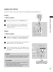
... OUT jacks. How to connect O Connect audio outputs to the digital audio input on the audio equipment. 0 Set the "TV Speaker option - O Set the "TV Speaker option - AUDIO OUT SETUP Send the TV's audio to the TV's OPTICAL or COAXIAL port of DIGITAL AUDIO OUT. See the external audio equipment instruction manual for operation. 33 How...
... OUT jacks. How to connect O Connect audio outputs to the digital audio input on the audio equipment. 0 Set the "TV Speaker option - O Set the "TV Speaker option - AUDIO OUT SETUP Send the TV's audio to the TV's OPTICAL or COAXIAL port of DIGITAL AUDIO OUT. See the external audio equipment instruction manual for operation. 33 How...

Owners Manual
Page 35
...program channels such as 2-1,2-2, etc. 34 When you toggle this button, the SimpLink menu appears at the remote control sensor on the TV. N TIMER Select the amount of AV devices connected to your preference. buttons MENU Displays the main menu. _h BRIGHT +/- MEDIAHosT... THUMBSTICK Navigate the on-screen menus and adjust the system set- (Up/Down/Left N Right/ENTER) tings to TV. NUMBER button BACK Tune to the last channel viewed. -- (DASH) Used to TV viewing from z fT1 any menu. WATCHING TV / CHANNEL CONTROL REMOTE CONTROL FUNCTIONS When using the remote ...
...program channels such as 2-1,2-2, etc. 34 When you toggle this button, the SimpLink menu appears at the remote control sensor on the TV. N TIMER Select the amount of AV devices connected to your preference. buttons MENU Displays the main menu. _h BRIGHT +/- MEDIAHosT... THUMBSTICK Navigate the on-screen menus and adjust the system set- (Up/Down/Left N Right/ENTER) tings to TV. NUMBER button BACK Tune to the last channel viewed. -- (DASH) Used to TV viewing from z fT1 any menu. WATCHING TV / CHANNEL CONTROL REMOTE CONTROL FUNCTIONS When using the remote ...


