
Owner's Manual
Page 1
OWNER'S MANUAL PLASMA TV Please read this manual carefully before operating your set and retain it for future reference. 42PT200 50PT200 42PT330 50PT330 42PT350 50PT350 50PV400 60PV400 50PV430 60PV430 50PV450 60PV450 42PT250U 50PT250U 50PV550U 60PV550U 42PT350C 50PT350C 50PV450C 60PV450C P/NO : SAC34173308 (1102-REV01) www.lg.com
OWNER'S MANUAL PLASMA TV Please read this manual carefully before operating your set and retain it for future reference. 42PT200 50PT200 42PT330 50PT330 42PT350 50PT350 50PV400 60PV400 50PV430 60PV430 50PV450 60PV450 42PT250U 50PT250U 50PV550U 60PV550U 42PT350C 50PT350C 50PV450C 60PV450C P/NO : SAC34173308 (1102-REV01) www.lg.com
Owner's Manual
Page 2
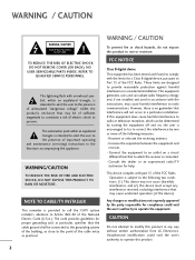
... device complies with the instructions, may cause undesired operation (of the building, as close to persons. NOTE TO CABLE/TV INSTALLER This reminder is provided to call the CATV system installer's attention to provide reasonable protection against harmful interference in accordance...the following measures: - Any changes or modifications not expressly approved by turning the equipment off and on a circuit different from LG Electronics. The exclamation point within the product's enclosure that interference will not occur in the literature accompanying the appliance. Increase ...
... device complies with the instructions, may cause undesired operation (of the building, as close to persons. NOTE TO CABLE/TV INSTALLER This reminder is provided to call the CATV system installer's attention to provide reasonable protection against harmful interference in accordance...the following measures: - Any changes or modifications not expressly approved by turning the equipment off and on a circuit different from LG Electronics. The exclamation point within the product's enclosure that interference will not occur in the literature accompanying the appliance. Increase ...
Owner's Manual
Page 4
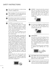
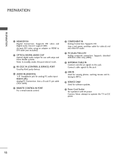
... 4 on shelves above the unit). 17 GROUNDING Ensure that appliance and has no additional outlets or branch circuits. Periodically examine the cord of the TV. 13 Do not allow an impact shock or any objects to fall into the product, and do not expose this apparatus or antenna during a thunder... mechanical abuse, such as this unit is connected to the AC wall outlet, it is recommend that is the disconnecting device. Do not touch the TV with a three-prong grounded AC plug must remain readily operable. 19 "As long as being twisted, kinked, pinched, closed in electric shock or ...
... 4 on shelves above the unit). 17 GROUNDING Ensure that appliance and has no additional outlets or branch circuits. Periodically examine the cord of the TV. 13 Do not allow an impact shock or any objects to fall into the product, and do not expose this apparatus or antenna during a thunder... mechanical abuse, such as this unit is connected to the AC wall outlet, it is recommend that is the disconnecting device. Do not touch the TV with a three-prong grounded AC plug must remain readily operable. 19 "As long as being twisted, kinked, pinched, closed in electric shock or ...
Owner's Manual
Page 5
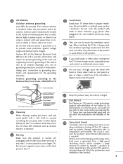
... performance and reliability of the product. 5 This noise is proper ventilation. ed sound does not affect the performance and reliability of the TV. 29 Generated Sound "Cracking" noise: A cracking noise that occurs when watching or turning off , unplugged and all cables have been removed.... It may become hot. Be sure the antenna system is required. When watching the TV for products where thermal deformation is grounded so as electric shock may occur. Electrical circuit humming/panel buzzing: A low level noise is ...
... performance and reliability of the product. 5 This noise is proper ventilation. ed sound does not affect the performance and reliability of the TV. 29 Generated Sound "Cracking" noise: A cracking noise that occurs when watching or turning off , unplugged and all cables have been removed.... It may become hot. Be sure the antenna system is required. When watching the TV for products where thermal deformation is grounded so as electric shock may occur. Electrical circuit humming/panel buzzing: A low level noise is ...
Owner's Manual
Page 6
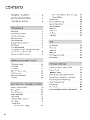
... Add / Delete Channel (Manual Tuning 41 - Auto Scan (Auto Tuning 40 - CONTENTS WARNING / CAUTION 2 SAFETY INSTRUCTIONS 3 FEATURE OF THIS TV 8 PREPARATION Accessories 9 Front Panel Information 10 Back Panel Information 11 Stand Instruction 13 Cable Management 15 Desktop Pedestal Installation 16 Swivel Stand 16 VESA... Wall Mounting 17 Securing the TV to the wall to prevent falling when the TV is used on a stand 18 Antenna or Cable Connection 19 EXTERNAL EQUIPMENT SETUP HD Receiver Setup ...
... Add / Delete Channel (Manual Tuning 41 - Auto Scan (Auto Tuning 40 - CONTENTS WARNING / CAUTION 2 SAFETY INSTRUCTIONS 3 FEATURE OF THIS TV 8 PREPARATION Accessories 9 Front Panel Information 10 Back Panel Information 11 Stand Instruction 13 Cable Management 15 Desktop Pedestal Installation 16 Swivel Stand 16 VESA... Wall Mounting 17 Securing the TV to the wall to prevent falling when the TV is used on a stand 18 Antenna or Cable Connection 19 EXTERNAL EQUIPMENT SETUP HD Receiver Setup ...
Owner's Manual
Page 7
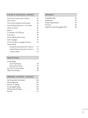
User Mode 85 Infinite Surround 86 Balance 87 TV Speakers On/Off Setup 88 Audio Reset 89 Stereo/SAP Broadcast Setup 90 Audio Language 91 On-Screen Menus Language Selection 92 Caption Mode - Auto ... Clock Setup 97 Auto On/Off Time Setting 98 Sleep Timer Setting 99 PARENTAL CONTROL / RATINGS Set Password & Lock System 100 Channel Blocking 103 Movie & TV Rating 104 Downloadable Rating 109 External Input Blocking 110 Key lock 111 APPENDIX Troubleshooting 112 Maintenance 114 Product Specifications 114 IR Codes 116 External Control...
User Mode 85 Infinite Surround 86 Balance 87 TV Speakers On/Off Setup 88 Audio Reset 89 Stereo/SAP Broadcast Setup 90 Audio Language 91 On-Screen Menus Language Selection 92 Caption Mode - Auto ... Clock Setup 97 Auto On/Off Time Setting 98 Sleep Timer Setting 99 PARENTAL CONTROL / RATINGS Set Password & Lock System 100 Channel Blocking 103 Movie & TV Rating 104 Downloadable Rating 109 External Input Blocking 110 Key lock 111 APPENDIX Troubleshooting 112 Maintenance 114 Product Specifications 114 IR Codes 116 External Control...
Owner's Manual
Page 8
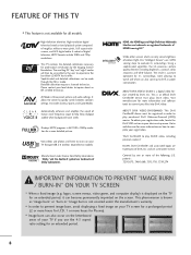
...and 720p resolutions. High-definition television. High-resolution digital television broadcast and playback system composed of DivX, Inc. This TV contains the detailed calibrations necessary for Plasma). Sophisticated and detailed calibrations can also savne up to inquire about an ISF ...display) is three preset picture and audio settings. "Dolby "and the double-D symbol are used under license. Using a sophisticated algorithm, the LG processes picture quality elements including brightness, contrast, color, sharpness and white balance. patents : 7,295,673; 7,460,668; 7,515,710; ...
...and 720p resolutions. High-definition television. High-resolution digital television broadcast and playback system composed of DivX, Inc. This TV contains the detailed calibrations necessary for Plasma). Sophisticated and detailed calibrations can also savne up to inquire about an ISF ...display) is three preset picture and audio settings. "Dolby "and the double-D symbol are used under license. Using a sophisticated algorithm, the LG processes picture quality elements including brightness, contrast, color, sharpness and white balance. patents : 7,295,673; 7,460,668; 7,515,710; ...
Owner's Manual
Page 9
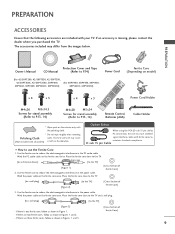
...Manual (Refer to P.14) Power Cord (For 42/50PT200, 42/50PT330, 42/50PT350, 42/50PT350C, 42/50PT250U, 50PV400, (For 60PV400, 60PV430, 60PV450, 50PV430, 50PV450, 50PV450C, 50PV550U) 60PV450C, 60PV550U) Ferrite Core (Depending on model) x 4 x 3 M4x26 M5x14.5 Screws for stand assembly (Refer to P.13, 14) x...there are three ferrite cores, follow as shown in the power cable. Wind the power cable on the exterior only with your TV. The accessories included may cause (Not included with ferrite cores to reduce the electromagnetic interference in Figures 1 and 3. [Cross ...
...Manual (Refer to P.14) Power Cord (For 42/50PT200, 42/50PT330, 42/50PT350, 42/50PT350C, 42/50PT250U, 50PV400, (For 60PV400, 60PV430, 60PV450, 50PV430, 50PV450, 50PV450C, 50PV550U) 60PV450C, 60PV550U) Ferrite Core (Depending on model) x 4 x 3 M4x26 M5x14.5 Screws for stand assembly (Refer to P.13, 14) x...there are three ferrite cores, follow as shown in the power cable. Wind the power cable on the exterior only with your TV. The accessories included may cause (Not included with ferrite cores to reduce the electromagnetic interference in Figures 1 and 3. [Cross ...
Owner's Manual
Page 10
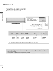
.... It may break, causing possible injury from your finger. The floor or the product may be damaged. 10 The LED is off while the TV remains on the glass stand or subject it to the surrounding conditions. Power/Standby Indicator Illuminates red in standby mode. G Do not drag the... TV. Remote Control Sensor HOME ENTER VOL CH POWER INPUT Button Button HOME Button ENTER Button VOLUME Buttons You can operate the buttons just by ...
.... It may break, causing possible injury from your finger. The floor or the product may be damaged. 10 The LED is off while the TV remains on the glass stand or subject it to the surrounding conditions. Power/Standby Indicator Illuminates red in standby mode. G Do not drag the... TV. Remote Control Sensor HOME ENTER VOL CH POWER INPUT Button Button HOME Button ENTER Button VOLUME Buttons You can operate the buttons just by ...
Owner's Manual
Page 12
... & red and white for analog PC audio input. Supports standard definition video only (480i). 8 ANTENNA/CABLE IN Connect over-the air signals to operate the TV on DC power. 12
... & red and white for analog PC audio input. Supports standard definition video only (480i). 8 ANTENNA/CABLE IN Connect over-the air signals to operate the TV on DC power. 12
Owner's Manual
Page 13
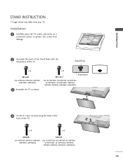
..., 42/50PT350C, 42/50PT250U, 50PV400, 50PV430, 50PV450, 50PV450C, 50PV550U) 4 Fix the 4 screws securely using the holes in the back of the TV. Installation 1 Carefully place the TV screen side down on a cushioned surface to protect the screen from your TV. x 4 x 4 M4x28 (For 60PV400, 60PV430..., 60PV450, 60PV450C, 60PV550U) M4x26 (For 42/50PT200, 42/50PT330, 42/50PT350, 42/50PT350C, 42/50PT250U, 50PV400, 50PV430, 50PV450, 50PV450C, 50PV550U) 13 PREPARATION STAND INSTRUCTION s Image shown...
..., 42/50PT350C, 42/50PT250U, 50PV400, 50PV430, 50PV450, 50PV450C, 50PV550U) 4 Fix the 4 screws securely using the holes in the back of the TV. Installation 1 Carefully place the TV screen side down on a cushioned surface to protect the screen from your TV. x 4 x 4 M4x28 (For 60PV400, 60PV430..., 60PV450, 60PV450C, 60PV550U) M4x26 (For 42/50PT200, 42/50PT330, 42/50PT350, 42/50PT350C, 42/50PT250U, 50PV400, 50PV430, 50PV450, 50PV450C, 50PV550U) 13 PREPARATION STAND INSTRUCTION s Image shown...
Owner's Manual
Page 14
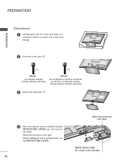
...use the PROTECTION COVER. 14 Attach the protection cover tape. PROTECTION COVER Fix a Guide to protect the screen from damage. 2 Loose the screws from TV. 4 After removing the stand, install the included PROTECTION COVER over the hole for the stand. x 4 x 4 M4x28 (For 60PV400, 60PV430, ...60PV450, 60PV450C, 60PV550U) M4x26 (For 42/50PT200, 42/50PT330, 42/50PT350, 42/50PT350C, 42/50PT250U, 50PV400, 50PV430, 50PV450, 50PV450C, 50PV550U) 3 Detach the stand from TV. Attach the protection cover tape. PREPARATION PREPARATION Detachment 1 Carefully place the...
...use the PROTECTION COVER. 14 Attach the protection cover tape. PROTECTION COVER Fix a Guide to protect the screen from damage. 2 Loose the screws from TV. 4 After removing the stand, install the included PROTECTION COVER over the hole for the stand. x 4 x 4 M4x28 (For 60PV400, 60PV430, ...60PV450, 60PV450C, 60PV550U) M4x26 (For 42/50PT200, 42/50PT330, 42/50PT350, 42/50PT350C, 42/50PT250U, 50PV400, 50PV430, 50PV450, 50PV450C, 50PV550U) 3 Detach the stand from TV. Attach the protection cover tape. PREPARATION PREPARATION Detachment 1 Carefully place the...
Owner's Manual
Page 15
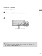
POWER CORD HOLDER CABLE HOLDER CAUTION G Do not move the TV by accident. 2 Gather and bind the cables with the cable holder. It will help prevent the power cable from being removed by holding the cable holder and power cord holder, as the cable holders may break, and injuries and damage to the TV may differ from your TV. 1 Install the power cord holder and power cord. PREPARATION CABLE MANAGEMENT s Image shown may occur. 15
POWER CORD HOLDER CABLE HOLDER CAUTION G Do not move the TV by accident. 2 Gather and bind the cables with the cable holder. It will help prevent the power cable from being removed by holding the cable holder and power cord holder, as the cable holders may break, and injuries and damage to the TV may differ from your TV. 1 Install the power cord holder and power cord. PREPARATION CABLE MANAGEMENT s Image shown may occur. 15
Owner's Manual
Page 16
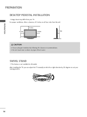
PREPARATION PREPARATION DESKTOP PEDESTAL INSTALLATION s Image shown may differ from the wall. 4 inches 4 inches 4 inches 4 inches CAUTION G Ensure adequate ventilation by 20 degrees to the left or right direction by following the clearance recommendations. For proper ventilation, allow a clearance of heat source. After installing the TV, you can adjust the TV manually to suit your TV. G Do not mount near or above any type of 4 inches on all models. SWIVEL STAND s This feature is not available for all four sides from your viewing position. 16
PREPARATION PREPARATION DESKTOP PEDESTAL INSTALLATION s Image shown may differ from the wall. 4 inches 4 inches 4 inches 4 inches CAUTION G Ensure adequate ventilation by 20 degrees to the left or right direction by following the clearance recommendations. For proper ventilation, allow a clearance of heat source. After installing the TV, you can adjust the TV manually to suit your TV. G Do not mount near or above any type of 4 inches on all models. SWIVEL STAND s This feature is not available for all four sides from your viewing position. 16
Owner's Manual
Page 17
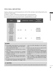
...depends on the wall mount used or the consumer fails to electric shock. 17 G Do not use an LG brand wall mount when mounting the TV to the instructions included with the VESA standard screw specifications, the length of accidents. We recommend that you ...damage to the inside to personal injury. It may fall , leading to the TV. Model VESA (A * B) A Standard Screw Quantity B Wall Mounting bracket (sold separately) 42/50PT200, 42/50PT330, 42/50PT350, 42/50PT350C, 50PV400, 50PV430, 50PV450, 400 * 400 M6 50PV450C, 42/50PT250U, 50PV550U PSW400B, 4 PSW400BG, ...
...depends on the wall mount used or the consumer fails to electric shock. 17 G Do not use an LG brand wall mount when mounting the TV to the instructions included with the VESA standard screw specifications, the length of accidents. We recommend that you ...damage to the inside to personal injury. It may fall , leading to the TV. Model VESA (A * B) A Standard Screw Quantity B Wall Mounting bracket (sold separately) 42/50PT200, 42/50PT330, 42/50PT350, 42/50PT350C, 50PV400, 50PV430, 50PV450, 400 * 400 M6 50PV450C, 42/50PT250U, 50PV550U PSW400B, 4 PSW400BG, ...
Owner's Manual
Page 18
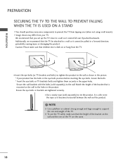
... a sturdy rope (sold separately) to the wall. We recommend that children don't climb on the wall to the holes in the picture. * If your TV. s Image shown may differ from your product has the bolts in the eye-bolts position before inserting the eye-bolts, loosen the bolts. * Insert the... eye-bolts or TV brackets/bolts and tighten them securely in a forward direction, potentially causing injury or damaging the product. Secure the wall brackets with the bolts (sold...
... a sturdy rope (sold separately) to the wall. We recommend that children don't climb on the wall to the holes in the picture. * If your TV. s Image shown may differ from your product has the bolts in the eye-bolts position before inserting the eye-bolts, loosen the bolts. * Insert the... eye-bolts or TV brackets/bolts and tighten them securely in a forward direction, potentially causing injury or damaging the product. Secure the wall brackets with the bolts (sold...
Owner's Manual
Page 19
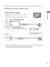
..., adjust antenna direction if needed. RF Coaxial Wire (75 Ω) ANTENNA /CABLE IN I If the antenna needs to be split for two TV's, install a 2-Way Signal Splitter. Cable Cable TV Wall Jack RF Coaxial Wire (75 Ω) Single-family Dwellings /Houses (Connect to wall jack for assistance. 19 I To prevent damage do...
..., adjust antenna direction if needed. RF Coaxial Wire (75 Ω) ANTENNA /CABLE IN I If the antenna needs to be split for two TV's, install a 2-Way Signal Splitter. Cable Cable TV Wall Jack RF Coaxial Wire (75 Ω) Single-family Dwellings /Houses (Connect to wall jack for assistance. 19 I To prevent damage do...
Owner's Manual
Page 20
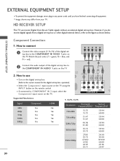
... connecting all equipment. EXTERNAL EQUIPMENT SETUP s To prevent the equipment damage, never plug in any power cords until you do receive digital signals from your TV. How to connect 1 Connect the video outputs (Y, PB, PR) of the digital set -top box. Match the jack colors (Y = green, PB =...to the figure as shown below. s Image shown may differ from a digital set -top box. s If connected to the COMPONENT IN AUDIO 1 jacks on the TV. 1 2 O IN /DVI) REMOTE CONTROL IN AV IN 1 VIDEO /MONO AUDIO 2 L R 1 VIDEO AUDIO COMPONENT IN ANT CA Supported Resolutions Signal 480i ...
... connecting all equipment. EXTERNAL EQUIPMENT SETUP s To prevent the equipment damage, never plug in any power cords until you do receive digital signals from your TV. How to connect 1 Connect the video outputs (Y, PB, PR) of the digital set -top box. Match the jack colors (Y = green, PB =...to the figure as shown below. s Image shown may differ from a digital set -top box. s If connected to the COMPONENT IN AUDIO 1 jacks on the TV. 1 2 O IN /DVI) REMOTE CONTROL IN AV IN 1 VIDEO /MONO AUDIO 2 L R 1 VIDEO AUDIO COMPONENT IN ANT CA Supported Resolutions Signal 480i ...
Owner's Manual
Page 21
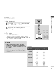
....00 59.939 60.00 23.94 29.97 21 In this case use I Select the HDMI1, 2, or 3 input source on the TV using the INPUT button on the TV. 2 No separate audio connection is necessary. How to connect 1 Connect the digital set -top box.) I Turn on the digital set-top box...
....00 59.939 60.00 23.94 29.97 21 In this case use I Select the HDMI1, 2, or 3 input source on the TV using the INPUT button on the TV. 2 No separate audio connection is necessary. How to connect 1 Connect the digital set -top box.) I Turn on the digital set-top box...
Owner's Manual
Page 22
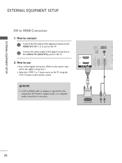
... for this connection. How to connect 1 Connect the DVI output of the digital set-top box to the HDMI/DVI IN 1 or 2 jack on the TV. 2 Connect the audio output of the digital set -top box.) I Turn on the digital set-top box. (Refer to use I Select the HDMI1 or 2 input... source on the TV using the INPUT button on the TV. 2. DVI doesn't support audio, so a separate audio connection is required for the digital set -top box to HDMI Connection 1. OPTICAL DIGITAL AUDIO...
... for this connection. How to connect 1 Connect the DVI output of the digital set-top box to the HDMI/DVI IN 1 or 2 jack on the TV. 2 Connect the audio output of the digital set -top box.) I Turn on the digital set-top box. (Refer to use I Select the HDMI1 or 2 input... source on the TV using the INPUT button on the TV. 2. DVI doesn't support audio, so a separate audio connection is required for the digital set -top box to HDMI Connection 1. OPTICAL DIGITAL AUDIO...


