Owner's Manual
Page 6
...DVD Setup 23 VCR Setup 25 Other A/V Source Setup 26 USB Connection 26 Audio Out Connection 27 PC Setup 28 WATCHING TV / CHANNEL CONTROL Remote Control Functions 34 Turning On TV 36 Channel Selection 36 Volume Adjustment 36 Initial Setting 37 On-Screen Menus Selection 38 Quick Menu 39 Channel ...SIMPLINK 50 USB Entry Modes 52 Photo List 53 Music List 59 Movie List 62 DivX Registration Code 68 Deactivation 69 PICTURE CONTROL Picture Size (Aspect Ratio) Control 70 Picture Wizard 72 Energy Saving 74 Preset Picture Settings(Picture Mode 75 Manual Picture Adjustment -
...DVD Setup 23 VCR Setup 25 Other A/V Source Setup 26 USB Connection 26 Audio Out Connection 27 PC Setup 28 WATCHING TV / CHANNEL CONTROL Remote Control Functions 34 Turning On TV 36 Channel Selection 36 Volume Adjustment 36 Initial Setting 37 On-Screen Menus Selection 38 Quick Menu 39 Channel ...SIMPLINK 50 USB Entry Modes 52 Photo List 53 Music List 59 Movie List 62 DivX Registration Code 68 Deactivation 69 PICTURE CONTROL Picture Size (Aspect Ratio) Control 70 Picture Wizard 72 Energy Saving 74 Preset Picture Settings(Picture Mode 75 Manual Picture Adjustment -
Owner's Manual
Page 9
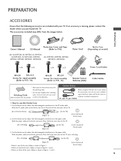
...) PC connection, the user must use the Ferrite Core 1. Use the ferrite core to P.13, 14) 1.5V 1.5V Power Cord Holder Remote Control, Batteries (AAA) Cable Holder * Wipe spots on the exterior only with ferrite cores to reduce the electromagnetic interference in Figures 1 and 2. ...the power cable. PREPARATION Owner's Manual Protection Cover and Tape CD Manual (Refer to P.14) Power Cord (For 42/50PT200, 42/50PT330, 42/50PT350, 42/50PT350C, 42/50PT250U, 50PV400, (For 60PV400, 60PV430, 60PV450, 50PV430, 50PV450, 50PV450C, 50PV550U) 60PV450C, 60PV550U) Ferrite Core (Depending on...
...) PC connection, the user must use the Ferrite Core 1. Use the ferrite core to P.13, 14) 1.5V 1.5V Power Cord Holder Remote Control, Batteries (AAA) Cable Holder * Wipe spots on the exterior only with ferrite cores to reduce the electromagnetic interference in Figures 1 and 2. ...the power cable. PREPARATION Owner's Manual Protection Cover and Tape CD Manual (Refer to P.14) Power Cord (For 42/50PT200, 42/50PT330, 42/50PT350, 42/50PT350C, 42/50PT250U, 50PV400, (For 60PV400, 60PV430, 60PV450, 50PV430, 50PV450, 50PV450C, 50PV550U) 60PV450C, 60PV550U) Ferrite Core (Depending on...
Owner's Manual
Page 10
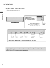
Remote Control Sensor HOME ENTER VOL CH POWER INPUT Button Button HOME Button ENTER Button VOLUME Buttons You can operate the buttons just by touching them lightly ...
Remote Control Sensor HOME ENTER VOL CH POWER INPUT Button Button HOME Button ENTER Button VOLUME Buttons You can operate the buttons just by touching them lightly ...
Owner's Manual
Page 12
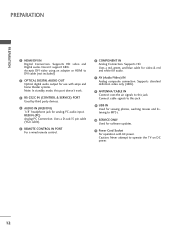
... signals to this port doesn't work. 3 RS-232C IN (CONTROL & SERVICE) PORT Used by third party devices. 4 AUDIO IN (RGB/DVI) 1/8" headphone jack for audio. 7 AV (Audio/Video) IN Analog composite connection. Uses a D-sub 15 pin cable (VGA cable). 5 REMOTE CONTROL IN PORT For a wired remote control. 6 COMPONENT IN Analog Connection. PREPARATION PREPARATION 1 HDMI/DVI...
... signals to this port doesn't work. 3 RS-232C IN (CONTROL & SERVICE) PORT Used by third party devices. 4 AUDIO IN (RGB/DVI) 1/8" headphone jack for audio. 7 AV (Audio/Video) IN Analog composite connection. Uses a D-sub 15 pin cable (VGA cable). 5 REMOTE CONTROL IN PORT For a wired remote control. 6 COMPONENT IN Analog Connection. PREPARATION PREPARATION 1 HDMI/DVI...
Owner's Manual
Page 20
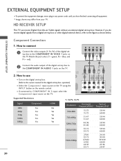
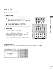
... your TV. Match the jack colors (Y = green, PB = blue, and PR = red). s If connected to the COMPONENT IN VIDEO 1 jacks on the TV. 1 2 O IN /DVI) REMOTE CONTROL IN AV IN 1 VIDEO /MONO AUDIO 2 L R 1 VIDEO AUDIO COMPONENT IN ANT CA Supported Resolutions Signal 480i 480p 720p 1080i 1080p Component Yes Yes Yes Yes.... (Refer to the owner's manual for the digital set -top box or other digital external device, refer to the COMPONENT IN AUDIO 1 jacks on the remote control. However, if you have finished connecting all equipment.
... your TV. Match the jack colors (Y = green, PB = blue, and PR = red). s If connected to the COMPONENT IN VIDEO 1 jacks on the TV. 1 2 O IN /DVI) REMOTE CONTROL IN AV IN 1 VIDEO /MONO AUDIO 2 L R 1 VIDEO AUDIO COMPONENT IN ANT CA Supported Resolutions Signal 480i 480p 720p 1080i 1080p Component Yes Yes Yes Yes.... (Refer to the owner's manual for the digital set -top box or other digital external device, refer to the COMPONENT IN AUDIO 1 jacks on the remote control. However, if you have finished connecting all equipment.
Owner's Manual
Page 21
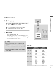
... on the TV. 2 No separate audio connection is necessary. HDMI-DTV OUTPUT 1 OPTICAL DIGITAL AUDIO OUT AUDIO (RGB/DVI) 2 1 HDMI/DVI IN RS-232C IN (CONTROL & SERVICE) RGB IN(PC) ! EXTERNAL EQUIPMENT SETUP HDMI Connection 1. How to connect 1 Connect the digital set-top box to the owner's manual for the digital...
... on the TV. 2 No separate audio connection is necessary. HDMI-DTV OUTPUT 1 OPTICAL DIGITAL AUDIO OUT AUDIO (RGB/DVI) 2 1 HDMI/DVI IN RS-232C IN (CONTROL & SERVICE) RGB IN(PC) ! EXTERNAL EQUIPMENT SETUP HDMI Connection 1. How to connect 1 Connect the digital set-top box to the owner's manual for the digital...
Owner's Manual
Page 22
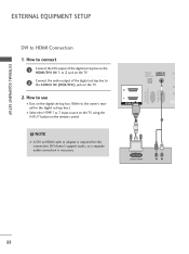
... audio connection is required for the digital set -top box to HDMI Connection 1. OPTICAL DIGITAL AUDIO OUT AUDIO IN (RGB/DVI) R CO RS-232C IN (CONTROL & SERVICE) RGB IN (PC) 2 2 1 1 HDMI/DVI IN 1 2 DVI-DTV OUTPUT R L 22 NOTE G A DVI to use I Select the HDMI1 or 2 input source on the TV using... box. (Refer to the owner's manual for this connection. EXTERNAL EQUIPMENT SETUP EXTERNAL EQUIPMENT SETUP DVI to the AUDIO IN (RGB/DVI) jack on the remote control. !
... audio connection is required for the digital set -top box to HDMI Connection 1. OPTICAL DIGITAL AUDIO OUT AUDIO IN (RGB/DVI) R CO RS-232C IN (CONTROL & SERVICE) RGB IN (PC) 2 2 1 1 HDMI/DVI IN 1 2 DVI-DTV OUTPUT R L 22 NOTE G A DVI to use I Select the HDMI1 or 2 input source on the TV using... box. (Refer to the owner's manual for this connection. EXTERNAL EQUIPMENT SETUP EXTERNAL EQUIPMENT SETUP DVI to the AUDIO IN (RGB/DVI) jack on the remote control. !
Owner's Manual
Page 23
How to use I Refer to the DVD player's manual for operating instructions. I Turn on the TV. DIO IN B/DVI) REMOTE CONTROL IN AV IN 1 VIDEO /MONO AUDIO 2 L R 1 VIDEO AUDIO A COMPONENT IN Component Input ports To get better picture quality, connect a DVD player to the COMPONENT IN ... the INPUT button on DVD player Y Y PB PR PB PR B-Y R-Y Cb Cr Pb Pr 23 Component ports on the TV Y Y Video output ports Y on the remote control. EXTERNAL EQUIPMENT SETUP DVD SETUP Component Connection 1.
How to use I Refer to the DVD player's manual for operating instructions. I Turn on the TV. DIO IN B/DVI) REMOTE CONTROL IN AV IN 1 VIDEO /MONO AUDIO 2 L R 1 VIDEO AUDIO A COMPONENT IN Component Input ports To get better picture quality, connect a DVD player to the COMPONENT IN ... the INPUT button on DVD player Y Y PB PR PB PR B-Y R-Y Cb Cr Pb Pr 23 Component ports on the TV Y Y Video output ports Y on the remote control. EXTERNAL EQUIPMENT SETUP DVD SETUP Component Connection 1.
Owner's Manual
Page 24
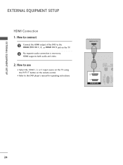
How to connect 1 Connect the HDMI output of the DVD to the DVD player's manual for operating instructions. I Select the HDMI1, 2, or 3 input source on the TV using the INPUT button on the TV. 2 No separate audio connection is necessary. EXTERNAL EQUIPMENT SETUP EXTERNAL EQUIPMENT SETUP HDMI Connection 1. How to use I Refer to the HDMI/DVI IN 1, 2, or HDMI IN 3 jack on the remote control. HDMI-DVD OUTPUT 1 OPTICAL DIGITAL AUDIO OUT AUD (RGB/D 2 1 HDMI/DVI IN RS-232C IN (CONTROL & SERVICE) RGB IN (PC) 24 HDMI supports both audio and video. 2.
How to connect 1 Connect the HDMI output of the DVD to the DVD player's manual for operating instructions. I Select the HDMI1, 2, or 3 input source on the TV using the INPUT button on the TV. 2 No separate audio connection is necessary. EXTERNAL EQUIPMENT SETUP EXTERNAL EQUIPMENT SETUP HDMI Connection 1. How to use I Refer to the HDMI/DVI IN 1, 2, or HDMI IN 3 jack on the remote control. HDMI-DVD OUTPUT 1 OPTICAL DIGITAL AUDIO OUT AUD (RGB/D 2 1 HDMI/DVI IN RS-232C IN (CONTROL & SERVICE) RGB IN (PC) 24 HDMI supports both audio and video. 2.
Owner's Manual
Page 25
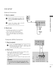
... audio cable from the VCR to the RF antenna in socket of the VCR. 2. N (PC) ANT IN S-VIDEO VIDEO L R ANT OUT OUTPUT SWITCH 1 UDIO B/DVI) REMOTE CONTROL IN AV IN 1 VIDEO L//MMOONNOO AUDIO R 2 L R 1 25 ANTENNA/ CABLE IN 1 2 Connect the antenna cable to the AUDIO L/MONO jack of the VCR to connect ...1 Connect the AUDIO/VIDEO jacks between TV and VCR. How to use I If connected to AV IN 2, select AV2 input source on the remote control. How to the ANTENNA/CABLE IN socket on the VCR. (Refer to the same channel number. I Set VCR output switch to 3 or 4 and ...
... audio cable from the VCR to the RF antenna in socket of the VCR. 2. N (PC) ANT IN S-VIDEO VIDEO L R ANT OUT OUTPUT SWITCH 1 UDIO B/DVI) REMOTE CONTROL IN AV IN 1 VIDEO L//MMOONNOO AUDIO R 2 L R 1 25 ANTENNA/ CABLE IN 1 2 Connect the antenna cable to the AUDIO L/MONO jack of the VCR to connect ...1 Connect the AUDIO/VIDEO jacks between TV and VCR. How to use I If connected to AV IN 2, select AV2 input source on the remote control. How to the ANTENNA/CABLE IN socket on the VCR. (Refer to the same channel number. I Set VCR output switch to 3 or 4 and ...

Owner's Manual
Page 26
I N jack on the side of TV. 2. For 42/50PT350, 42/50PT350C, 50/60PV450, 50/60PV450C, 42/50PT250U, 50/60PV550U 1. How to use I After connecting the USB I N jack, you use I Operate the corresponding external equipment. ... use the USB function. (G p.52) AV IN 2 26 EXTERNAL EQUIPMENT SETUP OTHER A/V SOURCE SETUP 1. How to AV IN 1 input, select the A V 1 input source on the remote control. Match the jack colors. (Video = yellow, Audio Left = white, and Audio Right = red) 2. I Select the A V 2 input source on the TV using the INPUT button on...
I N jack on the side of TV. 2. For 42/50PT350, 42/50PT350C, 50/60PV450, 50/60PV450C, 42/50PT250U, 50/60PV550U 1. How to use I After connecting the USB I N jack, you use I Operate the corresponding external equipment. ... use the USB function. (G p.52) AV IN 2 26 EXTERNAL EQUIPMENT SETUP OTHER A/V SOURCE SETUP 1. How to AV IN 1 input, select the A V 1 input source on the remote control. Match the jack colors. (Video = yellow, Audio Left = white, and Audio Right = red) 2. I Select the A V 2 input source on the TV using the INPUT button on...
Owner's Manual
Page 28
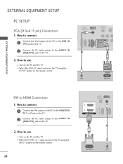
... source on the TV using the INPUT button on the PC and the TV. OPTICAL DIGITAL AUDIO OUT AUDIO IN (RGB/DVI) REMOTE CONTROL IN VIDEO 2 2 1 VIDEO COMPONEN 1 RS-232C IN (CONTROL & SERVICE) RGB IN (PC) 2 1 AUDIO RGB OUTPUT DVI to the AUDIO IN (RGB/DVI) jack on the TV. 2. I Turn... on the remote control. 28 OPTICAL AUDIO IN DIGITAL AUDIO OUT (RGB/DVI) 2 1 HDMI/DVI IN RS-232C IN (CONTROL & SERVICE) RGB IN (PC) 1 2 DVI-PC OUTPUT AUDIO I Turn on the remote control. How to the AUDIO IN (RGB/DVI) jack on the TV. 2. ...
... source on the TV using the INPUT button on the PC and the TV. OPTICAL DIGITAL AUDIO OUT AUDIO IN (RGB/DVI) REMOTE CONTROL IN VIDEO 2 2 1 VIDEO COMPONEN 1 RS-232C IN (CONTROL & SERVICE) RGB IN (PC) 2 1 AUDIO RGB OUTPUT DVI to the AUDIO IN (RGB/DVI) jack on the TV. 2. I Turn... on the remote control. 28 OPTICAL AUDIO IN DIGITAL AUDIO OUT (RGB/DVI) 2 1 HDMI/DVI IN RS-232C IN (CONTROL & SERVICE) RGB IN (PC) 1 2 DVI-PC OUTPUT AUDIO I Turn on the remote control. How to the AUDIO IN (RGB/DVI) jack on the TV. 2. ...

Owner's Manual
Page 34
The remote control may differ from standby. button USB, SIMPLINK Controls USB (List photo, List music, List movie) menu. Control buttons Controls the SIMPLINK compatible devices. LIST Displays the channel list. Color Access special functions in some...ENTER BACK EXIT FREEZE 34 G p.47 TV Select the remote operating mode: TV NUMBER button - (DASH) Used to standby. WATCHING TV / CHANNEL CONTROL WATCHING TV / CHANNEL CONTROL REMOTE CONTROL FUNCTIONS When using the remote control, aim it at the remote control sensor on Model) ENERGY SAVING Adjusts the Energy Saving. LIGHT...
The remote control may differ from standby. button USB, SIMPLINK Controls USB (List photo, List music, List movie) menu. Control buttons Controls the SIMPLINK compatible devices. LIST Displays the channel list. Color Access special functions in some...ENTER BACK EXIT FREEZE 34 G p.47 TV Select the remote operating mode: TV NUMBER button - (DASH) Used to standby. WATCHING TV / CHANNEL CONTROL WATCHING TV / CHANNEL CONTROL REMOTE CONTROL FUNCTIONS When using the remote control, aim it at the remote control sensor on Model) ENERGY SAVING Adjusts the Energy Saving. LIGHT...

Owner's Manual
Page 36
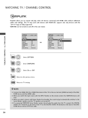
...mode to turn TV on, press the , INPUT, CH ( or ) button on the TV or press the POWER, INPUT, CH( or ), Number (0~9) button on the remote control. 2 Select the viewing source by pressing the MUTE or VOL (+ or -) button. 36 The TV reverts to select a channel number. VOLUME ADJUSTMENT Adjust the volume... 2 If you intend to switch the sound off, press the MUTE button. 3 You can cancel the Mute function by using the INPUT button on the remote control. 3 When finished using the TV, press the POWER button on vacation, disconnect the power plug from the wall power outlet. At this moment, TV is...
...mode to turn TV on, press the , INPUT, CH ( or ) button on the TV or press the POWER, INPUT, CH( or ), Number (0~9) button on the remote control. 2 Select the viewing source by pressing the MUTE or VOL (+ or -) button. 36 The TV reverts to select a channel number. VOLUME ADJUSTMENT Adjust the volume... 2 If you intend to switch the sound off, press the MUTE button. 3 You can cancel the Mute function by using the INPUT button on the remote control. 3 When finished using the TV, press the POWER button on vacation, disconnect the power plug from the wall power outlet. At this moment, TV is...
Owner's Manual
Page 50
WATCHING TV / CHANNEL CONTROL OPTION Language Input Label SIMPLINK Key Lock Caption Demo Mode ISM Method Set ID Initial Setting Move Enter : On : Off : Off : Off : Normal : 1 : Home Use ... with the HDMI cable. SIMPLINK can be turned on and off . WATCHING TV / CHANNEL CONTROL Simplink allows you to control and play the audio from the TV, connect the DIGITAL AUDIO OUT terminal on the back of the TV to the DIGITAL AUDIO IN terminal on the remote control, the SIMPLINK device will stop.
WATCHING TV / CHANNEL CONTROL OPTION Language Input Label SIMPLINK Key Lock Caption Demo Mode ISM Method Set ID Initial Setting Move Enter : On : Off : Off : Off : Normal : 1 : Home Use ... with the HDMI cable. SIMPLINK can be turned on and off . WATCHING TV / CHANNEL CONTROL Simplink allows you to control and play the audio from the TV, connect the DIGITAL AUDIO OUT terminal on the back of the TV to the DIGITAL AUDIO IN terminal on the remote control, the SIMPLINK device will stop.
Owner's Manual
Page 53
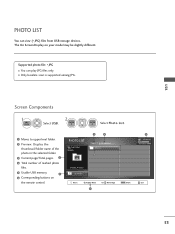
... 1 2 folder, 4 file(s) Up Folder Move PopUp Menu 6 CH Move Page MARK Mark 5 USB Device Free Space 150MB Exit 53 The On Screen Display on the remote control. Supported photo file: *.JPG I Only baseline scan is supported among JPG.
... 1 2 folder, 4 file(s) Up Folder Move PopUp Menu 6 CH Move Page MARK Mark 5 USB Device Free Space 150MB Exit 53 The On Screen Display on the remote control. Supported photo file: *.JPG I Only baseline scan is supported among JPG.

Owner's Manual
Page 59
The On Screen Display on the remote control. MUSIC LIST MP3 Arirang 3 4 Page 1/1 No Marked Title Up Folder Arirang Good Bye A 00:00 / 04:16 Up Folder Move PopUp Menu CH Move Page Q....
The On Screen Display on the remote control. MUSIC LIST MP3 Arirang 3 4 Page 1/1 No Marked Title Up Folder Arirang Good Bye A 00:00 / 04:16 Up Folder Move PopUp Menu CH Move Page Q....
Owner's Manual
Page 63
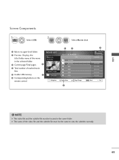
... subtitle file must be the same to view the subtitles normally 63 G The name of marked movie files. 5 Usable USB memory. 1 6 Corresponding buttons on the remote control. MOVIE LIST DriveA Butterfly 640x480, 707MB Up Folder Navigation 3 4 Page 1/1 No Marked Title Up Folder Butterfly B001 B002 B003 B004 PopUp Menu CH Page Change...
... subtitle file must be the same to view the subtitles normally 63 G The name of marked movie files. 5 Usable USB memory. 1 6 Corresponding buttons on the remote control. MOVIE LIST DriveA Butterfly 640x480, 707MB Up Folder Navigation 3 4 Page 1/1 No Marked Title Up Folder Butterfly B001 B002 B003 B004 PopUp Menu CH Page Change...

Owner's Manual
Page 65
... buttons repeatedly increases the fast forward/reverse speed. NOTE G Use the ( / ) bottons to move to speed up FF -> FFF -> FFFF -> FFFFF ->FFFFFF . USB Using the remote control You can be viewed on the screen. repeatedly press the F F(GG) button to a specific frame forward or backward while playing a movie. (The ( / )bottons may not...
... buttons repeatedly increases the fast forward/reverse speed. NOTE G Use the ( / ) bottons to move to speed up FF -> FFF -> FFFF -> FFFFF ->FFFFFF . USB Using the remote control You can be viewed on the screen. repeatedly press the F F(GG) button to a specific frame forward or backward while playing a movie. (The ( / )bottons may not...
Owner's Manual
Page 70
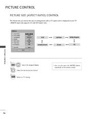
... Program 4:3 1 Q.MENU 2 Select the Aspect Ratio. s You can also press the RATIO button repeatedly on your TV. PICTURE CONTROL PICTURE SIZE (ASPECT RATIO) CONTROL This feature lets you choose the way an analog picture with a 4:3 aspect ratio is displayed on the remote control. Select the desired picture format. 3 EXIT Return to TV viewing. PICTURE...
... Program 4:3 1 Q.MENU 2 Select the Aspect Ratio. s You can also press the RATIO button repeatedly on your TV. PICTURE CONTROL PICTURE SIZE (ASPECT RATIO) CONTROL This feature lets you choose the way an analog picture with a 4:3 aspect ratio is displayed on the remote control. Select the desired picture format. 3 EXIT Return to TV viewing. PICTURE...


