
Owner's Manual (English)
Page 1
... / www.lg.cwaw/ww.lgwuws.alg.comm/ ewrwciwa.l.lgco.cma Model: This product qualifies for ENERGY STAR in which power savings will increase power consumption that could exceed the limits necessary to quality for future reference. PLASMA TV OWNER'S MANUAL 42PQ20 50PQ20 42PQ30 50PQ30 42PQ31 50PQ31 42PQ60 50PQ60 50PS30 50PS60 60PS60 42PQ30C 50PQ30C 50PS60C...
... / www.lg.cwaw/ww.lgwuws.alg.comm/ ewrwciwa.l.lgco.cma Model: This product qualifies for ENERGY STAR in which power savings will increase power consumption that could exceed the limits necessary to quality for future reference. PLASMA TV OWNER'S MANUAL 42PQ20 50PQ20 42PQ30 50PQ30 42PQ31 50PQ31 42PQ60 50PQ60 50PS30 50PS60 60PS60 42PQ30C 50PQ30C 50PS60C...

Owner's Manual (English)
Page 4
..., have the cord replaced with something. 14 CAUTION concerning the Power Cord: It is the disconnecting device. Periodically examine the cord of this owner's manual to a three-prong grounded AC outlet). Do not pull on shelves above the unit). 17 GROUNDING Ensure that appliances be certain. To reduce the ...outlets. Do not use of the TV. 13 Do not allow an impact shock or any objects to install the TV by SWITCH" (Except 42/50PQ30C, 50/60PS60C) The plug must be connected to be placed upon . Pay particular attention to telephone wires, lightening rods, or gas pipes. Protect the...
..., have the cord replaced with something. 14 CAUTION concerning the Power Cord: It is the disconnecting device. Periodically examine the cord of this owner's manual to a three-prong grounded AC outlet). Do not pull on shelves above the unit). 17 GROUNDING Ensure that appliances be certain. To reduce the ...outlets. Do not use of the TV. 13 Do not allow an impact shock or any objects to install the TV by SWITCH" (Except 42/50PQ30C, 50/60PS60C) The plug must be connected to be placed upon . Pay particular attention to telephone wires, lightening rods, or gas pipes. Protect the...
Owner's Manual (English)
Page 6
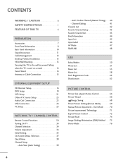
...Cable Connection 15 EXTERNAL EQUIPMENT SETUP HD Receiver Setup 16 DVD Setup 19 VCR Setup 21 Other A/V Source Setup 23 Audio Out Connection 23 USB Connection 24 PC Setup 25 WATCHING TV / CHANNEL CONTROL Remote Control Functions 30 Turning On TV 34 Channel Selection 34 Volume Adjustment 34 ...List 42 Favorite Channel Setup 43 Favorite Channel List 43 Brief Information 44 Input List 45 Input Label 46 AV Mode 47 SIMPLINK 48 USB Entry Modes 50 Photo List 51 Music List 55 Movie List 58 DivX Registration Code 62 Deactivation 63 PICTURE CONTROL Picture Size (Aspect Ratio...
...Cable Connection 15 EXTERNAL EQUIPMENT SETUP HD Receiver Setup 16 DVD Setup 19 VCR Setup 21 Other A/V Source Setup 23 Audio Out Connection 23 USB Connection 24 PC Setup 25 WATCHING TV / CHANNEL CONTROL Remote Control Functions 30 Turning On TV 34 Channel Selection 34 Volume Adjustment 34 ...List 42 Favorite Channel Setup 43 Favorite Channel List 43 Brief Information 44 Input List 45 Input Label 46 AV Mode 47 SIMPLINK 48 USB Entry Modes 50 Photo List 51 Music List 55 Movie List 58 DivX Registration Code 62 Deactivation 63 PICTURE CONTROL Picture Size (Aspect Ratio...
Owner's Manual (English)
Page 7
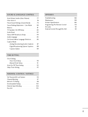
Caption Option 89 TIME SETTING Clock Setting - Auto Clock Setup 90 Manual Clock Setup 91 Auto On/Off Time Setting 92 Sleep Timer Setting 93 PARENTAL CONTROL / RATINGS Set Password & Lock System 94 Channel Blocking 97 Movie & ...
Caption Option 89 TIME SETTING Clock Setting - Auto Clock Setup 90 Manual Clock Setup 91 Auto On/Off Time Setting 92 Sleep Timer Setting 93 PARENTAL CONTROL / RATINGS Set Password & Lock System 94 Channel Blocking 97 Movie & ...
Owner's Manual (English)
Page 9
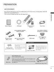
...2 ENERGIYNSAPVUINGT 753 86 LIST 0 9 VOL MUTE FLASHBK FREEZE CH P A G ENTER E MENU Q.MENU FREEZE RATIO RETURN 1.5V 1.5V FAV MARK Owner's Manual CD Manual Remote Control, Batteries Power Cord (Except 60PS60, 60PS60C, 60PS70, 60PS80) (Only 60PS60, 60PS60C, 50/60PS70, 50/60PS80) or Protection Cover (Refer to P.... of ferrite core (Not included with all models) scratch or discoloration. Option Extras D-sub 15 pin Cable When using the VGA (D-sub 15 pin cable) PC connection, the user must use shielded signal interface cables with the polishing cloth. Polishing Cloth ...
...2 ENERGIYNSAPVUINGT 753 86 LIST 0 9 VOL MUTE FLASHBK FREEZE CH P A G ENTER E MENU Q.MENU FREEZE RATIO RETURN 1.5V 1.5V FAV MARK Owner's Manual CD Manual Remote Control, Batteries Power Cord (Except 60PS60, 60PS60C, 60PS70, 60PS80) (Only 60PS60, 60PS60C, 50/60PS70, 50/60PS80) or Protection Cover (Refer to P.... of ferrite core (Not included with all models) scratch or discoloration. Option Extras D-sub 15 pin Cable When using the VGA (D-sub 15 pin cable) PC connection, the user must use shielded signal interface cables with the polishing cloth. Polishing Cloth ...

Owner's Manual (English)
Page 15
...Screw Quantity B Wall Mounting bracket (sold separately) 42PQ20, 42PQ30, 42PQ31, 42PQ30C, 42PQ60, 50PQ20, 50PQ30, 50PQ31, 50PQ30C, 400 * 400 M6 50PQ60, 50PS30, 50PS60, 50PS60C, 50PS70, 50PS80 4 AW-50PG60MS 60PS60, 60PS60C, 60PS70, ...M8 4 AW-60PG60MS ! G When purchasing our wall mount kit, a detailed installation manual and all four sides from your wall mount on all parts necessary for TV damage or... standard dimension, as they may cause damage to the inside to personal injury. G LG is used . PREPARATION DESKTOP PEDESTAL INSTALLATION ■ Image shown may differ from the ...
...Screw Quantity B Wall Mounting bracket (sold separately) 42PQ20, 42PQ30, 42PQ31, 42PQ30C, 42PQ60, 50PQ20, 50PQ30, 50PQ31, 50PQ30C, 400 * 400 M6 50PQ60, 50PS30, 50PS60, 50PS60C, 50PS70, 50PS80 4 AW-50PG60MS 60PS60, 60PS60C, 60PS70, ...M8 4 AW-60PG60MS ! G When purchasing our wall mount kit, a detailed installation manual and all four sides from your wall mount on all parts necessary for TV damage or... standard dimension, as they may cause damage to the inside to personal injury. G LG is used . PREPARATION DESKTOP PEDESTAL INSTALLATION ■ Image shown may differ from the ...
Owner's Manual (English)
Page 16
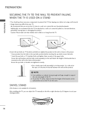
Additionally, we recommend that you can adjust the TV manually to the left or right direction by 20 degrees to support the size and weight of the TV. SWIVEL STAND (This feature is not available ...
Additionally, we recommend that you can adjust the TV manually to the left or right direction by 20 degrees to support the size and weight of the TV. SWIVEL STAND (This feature is not available ...
Owner's Manual (English)
Page 18
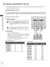
...blue, and PR = red). COMPONENT IN VIDEO AUDIO 2 1 L R AV IN 1 2 Connect the audio output of the digital settop box to the owner's manual for the digital set -top box. REMOTE CONTROL IN S-VIDEO VIDEO /MONO AUDIO AN CA 2. operation) ■ Select the Component1 input source on the TV..., refer to use ■ Turn on the TV. 1 2 Y PB PR L R Supported Resolutions Signal 480i 480p 720p 1080i 1080p Component Yes Yes Yes Yes Yes HDMI No Yes Yes Yes Yes Y, CB/PB, CR/PR Resolution Horizontal Vertical Frequency(KHz) Frequency(Hz) 720x480i 720x480p 1280x720p 1920x1080i...
...blue, and PR = red). COMPONENT IN VIDEO AUDIO 2 1 L R AV IN 1 2 Connect the audio output of the digital settop box to the owner's manual for the digital set -top box. REMOTE CONTROL IN S-VIDEO VIDEO /MONO AUDIO AN CA 2. operation) ■ Select the Component1 input source on the TV..., refer to use ■ Turn on the TV. 1 2 Y PB PR L R Supported Resolutions Signal 480i 480p 720p 1080i 1080p Component Yes Yes Yes Yes Yes HDMI No Yes Yes Yes Yes Y, CB/PB, CR/PR Resolution Horizontal Vertical Frequency(KHz) Frequency(Hz) 720x480i 720x480p 1280x720p 1920x1080i...
Owner's Manual (English)
Page 19
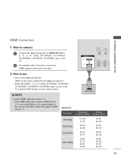
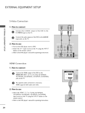
... over version 1.3. If the HDMI cables don't support HDMI version 1.3, it can cause flickers or no screen display. How to connect 1 Connect the digital set-top box to the owner's manual for the digital set -top box. (Refer to HDMI/DVI IN 1, 2, 3 or 4 (Only 42/50PQ60, 50/60PS60, 50/60PS60C, ...50/60PS70, 50/60PS80) jack on the remote control. ! HDMI supports both audio and video. HDMI Connection EXTERNAL EQUIPMENT SETUP RGB(PC) RS-...
... over version 1.3. If the HDMI cables don't support HDMI version 1.3, it can cause flickers or no screen display. How to connect 1 Connect the digital set-top box to the owner's manual for the digital set -top box. (Refer to HDMI/DVI IN 1, 2, 3 or 4 (Only 42/50PQ60, 50/60PS60, 50/60PS60C, ...50/60PS70, 50/60PS80) jack on the remote control. ! HDMI supports both audio and video. HDMI Connection EXTERNAL EQUIPMENT SETUP RGB(PC) RS-...
Owner's Manual (English)
Page 20
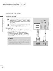
...necessary. OPTICAL DIGITAL AUDIO OUT AUDIO IN (RGB/DVI) HDMI/DVI IN 2 1 REMOTE CONTROL IN 1 2 DVI-DTV OUTPUT R L AV IN 1 18 DVI doesn't support audio, so a separate audio connection is required for the digital set -top box to the owner's manual for this connection. How to use ■ Turn on... the digital set-top box. (Refer to the AUDIO IN (RGB/DVI) jack on the remote control. ! RGB IN (PC) RS-232C IN (CONTROL & SERVICE) EXTERNAL EQUIPMENT SETUP EXTERNAL EQUIPMENT SETUP DVI to the HDMI/DVI IN 1, 2,...
...necessary. OPTICAL DIGITAL AUDIO OUT AUDIO IN (RGB/DVI) HDMI/DVI IN 2 1 REMOTE CONTROL IN 1 2 DVI-DTV OUTPUT R L AV IN 1 18 DVI doesn't support audio, so a separate audio connection is required for the digital set -top box to the owner's manual for this connection. How to use ■ Turn on... the digital set-top box. (Refer to the AUDIO IN (RGB/DVI) jack on the remote control. ! RGB IN (PC) RS-232C IN (CONTROL & SERVICE) EXTERNAL EQUIPMENT SETUP EXTERNAL EQUIPMENT SETUP DVI to the HDMI/DVI IN 1, 2,...
Owner's Manual (English)
Page 21
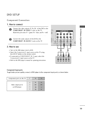
...) DVD SETUP Component Connection 1. Match the jack colors (Y = green, PB = blue, and PR = red). 2 Connect the audio outputs of the DVD to the DVD player's manual for operating instructions. How to connect 1 Connect the video outputs (Y, PB, PR) of the DVD to the component input ports as shown below.
...) DVD SETUP Component Connection 1. Match the jack colors (Y = green, PB = blue, and PR = red). 2 Connect the audio outputs of the DVD to the DVD player's manual for operating instructions. How to connect 1 Connect the video outputs (Y, PB, PR) of the DVD to the component input ports as shown below.
Owner's Manual (English)
Page 22
How to the DVD player's manual for operating instructions. How to connect 1 Connect the HDMI output of the DVD to the AUDIO input jacks on the remote control. ■ Refer to use ■ Turn on the DVD player, insert ...button on the TV. 2. How to the DVD player's manual for operating instructions. RGB(PC) S-VIDEO AUDIO L R 1 2 COMPONENT IN VIDEO AUDIO 2 1 L R AV IN 1 AN REMOTE S-VIDEO VIDEO /MONO AUDIO CA CONTROL IN (CONTROL & SERVICE) HDMI/DVI IN 2 1 1 HDMI-DVD OUTPUT 20 HDMI Connection 1. HDMI supports both audio and video. 2. How to connect 1 ...
How to the DVD player's manual for operating instructions. How to connect 1 Connect the HDMI output of the DVD to the AUDIO input jacks on the remote control. ■ Refer to use ■ Turn on the DVD player, insert ...button on the TV. 2. How to the DVD player's manual for operating instructions. RGB(PC) S-VIDEO AUDIO L R 1 2 COMPONENT IN VIDEO AUDIO 2 1 L R AV IN 1 AN REMOTE S-VIDEO VIDEO /MONO AUDIO CA CONTROL IN (CONTROL & SERVICE) HDMI/DVI IN 2 1 1 HDMI-DVD OUTPUT 20 HDMI Connection 1. HDMI supports both audio and video. 2. How to connect 1 ...

Owner's Manual (English)
Page 23
How to connect 1 Connect the RF antenna out socket of the VCR to the ANTENNA/CABLE IN socket on the VCR. (Refer to the RF antenna in socket of the VCR. 2. EXTERNAL EQUIPMENT SETUP AV IN 1 VCR SETUP Antenna Connection 1. How to use ■ Set VCR output switch to 3 or 4 and then tune TV to the same channel number. ■ Insert a video tape into the VCR and press PLAY on the TV. 2 Connect the antenna cable to the VCR owner's manual.) ANTENNA/ CABLE IN 1 ANT OUT S-VIDEO VIDEO L R ANT IN OUTPUT SWITCH Wall Jack 2 Antenna 21
How to connect 1 Connect the RF antenna out socket of the VCR to the ANTENNA/CABLE IN socket on the VCR. (Refer to the RF antenna in socket of the VCR. 2. EXTERNAL EQUIPMENT SETUP AV IN 1 VCR SETUP Antenna Connection 1. How to use ■ Set VCR output switch to 3 or 4 and then tune TV to the same channel number. ■ Insert a video tape into the VCR and press PLAY on the TV. 2 Connect the antenna cable to the VCR owner's manual.) ANTENNA/ CABLE IN 1 ANT OUT S-VIDEO VIDEO L R ANT IN OUTPUT SWITCH Wall Jack 2 Antenna 21

Owner's Manual (English)
Page 24
... ■ Insert a video tape into the VCR and press PLAY on the TV. 2 Connect the audio outputs of the TV. How to the VCR owner's manual.) ■ Select the A V 1 input source on the TV using the INPUT button on the remote control. 1 L R AV IN 1 RGB IN (PC) ■ If connected to...) ANT OUT OUTPUT SWITCH 1 2. How to use ■ Insert a video tape into the VCR and press PLAY on the VCR. (Refer to the VCR owner's manual.) UDIO IN GB/DVI) COMPONENT IN VIDEO AUDIO 2 ■ Select the A V 1 input source on the TV using the INPUT button on the remote control. ! How...
... ■ Insert a video tape into the VCR and press PLAY on the TV. 2 Connect the audio outputs of the TV. How to the VCR owner's manual.) ■ Select the A V 1 input source on the TV using the INPUT button on the remote control. 1 L R AV IN 1 RGB IN (PC) ■ If connected to...) ANT OUT OUTPUT SWITCH 1 2. How to use ■ Insert a video tape into the VCR and press PLAY on the VCR. (Refer to the VCR owner's manual.) UDIO IN GB/DVI) COMPONENT IN VIDEO AUDIO 2 ■ Select the A V 1 input source on the TV using the INPUT button on the remote control. ! How...
Owner's Manual (English)
Page 25
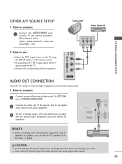
.... Match the jack colors. (Video = yellow, Audio Left = white, and Audio Right = red) Camcorder Video Game Set VIDEO L R USB IN VIDEO L/MONO AUDIO R HDMI IN 3 EXTERNAL EQUIPMENT SETUP 2. OPTICAL DIGITAL AUDIO AUDIO OUT (RGB/DVI) RGB(PC) RS-232C IN (CONTROL & SERVICE...option - Off" in the menu. (G p.82) CAUTION G Do not look into the optical output port. See the external audio equipment instruction manual for operation. NOTE 2 G When connecting with ACP (Audio Copy Protection) function may damage your vision. How to external audio equipment via the ...
.... Match the jack colors. (Video = yellow, Audio Left = white, and Audio Right = red) Camcorder Video Game Set VIDEO L R USB IN VIDEO L/MONO AUDIO R HDMI IN 3 EXTERNAL EQUIPMENT SETUP 2. OPTICAL DIGITAL AUDIO AUDIO OUT (RGB/DVI) RGB(PC) RS-232C IN (CONTROL & SERVICE...option - Off" in the menu. (G p.82) CAUTION G Do not look into the optical output port. See the external audio equipment instruction manual for operation. NOTE 2 G When connecting with ACP (Audio Copy Protection) function may damage your vision. How to external audio equipment via the ...
Owner's Manual (English)
Page 29
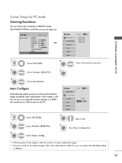
... 0R G • Advanced Control • Reset Screen (RGB-PC) Screen Resolution G Auto config. After adjustment, if the image is still not correct, try using the manual settings or a different resolution or refresh rate on the PC. The Position, Phase, and Size can adjust the Position, Si ze or Phase. 27 Select...
... 0R G • Advanced Control • Reset Screen (RGB-PC) Screen Resolution G Auto config. After adjustment, if the image is still not correct, try using the manual settings or a different resolution or refresh rate on the PC. The Position, Phase, and Size can adjust the Position, Si ze or Phase. 27 Select...

Owner's Manual (English)
Page 30
...; P h a s e: This function allows you prefer. ■ S i z e: This function is not clear after auto adjustment and especially if characters are still trembling, adjust the picture phase manually. Position G Size Phase Reset Move MENU Prev. Select Position, Si ze, or Phase. Select Screen (RGB-PC).
...; P h a s e: This function allows you prefer. ■ S i z e: This function is not clear after auto adjustment and especially if characters are still trembling, adjust the picture phase manually. Position G Size Phase Reset Move MENU Prev. Select Position, Si ze, or Phase. Select Screen (RGB-PC).

Owner's Manual (English)
Page 37
It can also be displayed on the screen when turning the TV on until the Initial setting procedure is "Home Use". Picture mode" manually while inspecting the TV, but the TV will be activated from the user menus. ■ Default selection is completed. Factory defaults are set the essential ...
It can also be displayed on the screen when turning the TV on until the Initial setting procedure is "Home Use". Picture mode" manually while inspecting the TV, but the TV will be activated from the user menus. ■ Default selection is completed. Factory defaults are set the essential ...

Owner's Manual (English)
Page 38
WATCHING TV / CHANNEL CONTROL WATCHING TV / CHANNEL CONTROL Step3. The previous channel information will be updated during Auto Tuning. Step4. Previous Next 1 ENTER Start Auto Tuning. 36 Time setting Time Setting Current Time Setting Year Month Date Hour Minute Time Zone Daylight Saving F Auto G 2007 11 15 5 PM 52 Eastern Off Previous Next 1 Select A ut o or Manual. 2 ENTER Select desired time option. Auto Tuning Auto Tuning Check your antenna connection.
WATCHING TV / CHANNEL CONTROL WATCHING TV / CHANNEL CONTROL Step3. The previous channel information will be updated during Auto Tuning. Step4. Previous Next 1 ENTER Start Auto Tuning. 36 Time setting Time Setting Current Time Setting Year Month Date Hour Minute Time Zone Daylight Saving F Auto G 2007 11 15 5 PM 52 Eastern Off Previous Next 1 Select A ut o or Manual. 2 ENTER Select desired time option. Auto Tuning Auto Tuning Check your antenna connection.
Owner's Manual (English)
Page 39
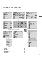
... menu. ON-SCREEN MENUS SELECTION Your TV's OSD (On Screen Display) may differ slightly from that shown in this manual. Only 50/60PS60, 50/60PS60C CHANNEL Auto Tuning Manual Tuning Channel Edit Move Enter PICTURE Move Aspect Ratio : 16:9 Picture Wizard Energy Saving : Off Picture Mode : Standard... On Key Lock : Off Caption : Off Demo Mode : Off ISM Method : Normal Set ID : 1 E CHANNEL PICTURE AUDIO TIME OPTION LOCK INPUT USB or TIME Clock Off Time : Off On Time : Off Sleep Timer : Off Move Enter LOCK Move Enter Lock System : Off Set Password Block Channel ...
... menu. ON-SCREEN MENUS SELECTION Your TV's OSD (On Screen Display) may differ slightly from that shown in this manual. Only 50/60PS60, 50/60PS60C CHANNEL Auto Tuning Manual Tuning Channel Edit Move Enter PICTURE Move Aspect Ratio : 16:9 Picture Wizard Energy Saving : Off Picture Mode : Standard... On Key Lock : Off Caption : Off Demo Mode : Off ISM Method : Normal Set ID : 1 E CHANNEL PICTURE AUDIO TIME OPTION LOCK INPUT USB or TIME Clock Off Time : Off On Time : Off Sleep Timer : Off Move Enter LOCK Move Enter Lock System : Off Set Password Block Channel ...

