User Manual
Page 4
... 9 Antenna Connection 10 Swivel Stand 10 EXTERNAL EQUIPMENT SETUP HD Receiver Setup 11 DVD Setup 13 VCR Setup 16 Insertion of CI Module 19 Digital Audio Out Setup 19 Other A/V Source Setup 20 Usb Setup 20 PC Setup 21 - Button Function in NOW/NEXT Guide Mode . 68 - Picture Mode-User option...
... 9 Antenna Connection 10 Swivel Stand 10 EXTERNAL EQUIPMENT SETUP HD Receiver Setup 11 DVD Setup 13 VCR Setup 16 Insertion of CI Module 19 Digital Audio Out Setup 19 Other A/V Source Setup 20 Usb Setup 20 PC Setup 21 - Button Function in NOW/NEXT Guide Mode . 68 - Picture Mode-User option...
User Manual
Page 5
... Setting Adjustment -User Mode 87 SRS TruSurround XT 87 Clear Voice II 88 Balance 88 TV Speakers On/ Off Setup 89 Selecting Digital Audio Out 90 Audio Reset 91 Audio description 92 I/II - Speaker Sound Output Selection 94 On-Screen Menu Language/Country Selection . . 95 Language Selection (In Digital Mode only) . . . . 96 TIME...
... Setting Adjustment -User Mode 87 SRS TruSurround XT 87 Clear Voice II 88 Balance 88 TV Speakers On/ Off Setup 89 Selecting Digital Audio Out 90 Audio Reset 91 Audio description 92 I/II - Speaker Sound Output Selection 94 On-Screen Menu Language/Country Selection . . 95 Language Selection (In Digital Mode only) . . . . 96 TIME...

User Manual
Page 8
...5 1 Power Cord Socket This TV operates on an AC power. Never attempt to operate the TV on DC power. 2 OPTICAL DIGITAL AUDIO OUT Connect digital audio to the RS-232C port on the Specifications page. This port is used for Service or Hotel mode. 6 Antenna Input Connect RF antenna... to this jack. 7 PCMCIA (Personal Computer Memory Card International Association) Card Slot Insert the CI Module to a Digital Audio Component. The voltage is not available in all countries.) 8 SERVICE ONLY PORT 6 Connect to PCMCIA CARD SLOT. (This feature is indicated on a ...
...5 1 Power Cord Socket This TV operates on an AC power. Never attempt to operate the TV on DC power. 2 OPTICAL DIGITAL AUDIO OUT Connect digital audio to the RS-232C port on the Specifications page. This port is used for Service or Hotel mode. 6 Antenna Input Connect RF antenna... to this jack. 7 PCMCIA (Personal Computer Memory Card International Association) Card Slot Insert the CI Module to a Digital Audio Component. The voltage is not available in all countries.) 8 SERVICE ONLY PORT 6 Connect to PCMCIA CARD SLOT. (This feature is indicated on a ...

User Manual
Page 9
...is used for Service or Hotel mode. 8 Component Input Connect a component video/audio device to these jacks. 3 OPTICAL DIGITAL AUDIO OUT 9 Antenna Input Connect digital audio to HDMI cable. 12 Audio/Video Input Connect audio/video output from an external 6 RGB Input Connect the output from a PC ... HDMI IN 3 R 42/50PQ20**, 42/50PQ30**, 42/50PQ60**, 50PS20**, 50PS30**, 50PS60**, 60PS40** PREPARATION AV IN 3 10 1 USB IN SERVICE ONLY VARIABLE AUDIO OUT VIDEO L/MONO AUDIO R S-VIDEO HDMI IN 3 11 2 3 4 5 HDMI IN 2 1 12 HDMI/DVI IN AV IN 3 5 6 7 8 9 1 Power Cord Socket This TV...
...is used for Service or Hotel mode. 8 Component Input Connect a component video/audio device to these jacks. 3 OPTICAL DIGITAL AUDIO OUT 9 Antenna Input Connect digital audio to HDMI cable. 12 Audio/Video Input Connect audio/video output from an external 6 RGB Input Connect the output from a PC ... HDMI IN 3 R 42/50PQ20**, 42/50PQ30**, 42/50PQ60**, 50PS20**, 50PS30**, 50PS60**, 60PS40** PREPARATION AV IN 3 10 1 USB IN SERVICE ONLY VARIABLE AUDIO OUT VIDEO L/MONO AUDIO R S-VIDEO HDMI IN 3 11 2 3 4 5 HDMI IN 2 1 12 HDMI/DVI IN AV IN 3 5 6 7 8 9 1 Power Cord Socket This TV...

User Manual
Page 12
... wall jack for connection. PREPARATION PREPARATION I For optimum picture quality, adjust antenna direction. I In poor signal areas, to the antenna as shown above. VIDEO L/MONO AUDIO R S-VIDEO HDMI IN 3 AV IN 3 Wall Antenna Socket Multi-family Dwellings/Apartments (Connect to wall antenna socket) Outdoor Antenna (VHF, UHF) RF Coaxial Wire (75...
... wall jack for connection. PREPARATION PREPARATION I For optimum picture quality, adjust antenna direction. I In poor signal areas, to the antenna as shown above. VIDEO L/MONO AUDIO R S-VIDEO HDMI IN 3 AV IN 3 Wall Antenna Socket Multi-family Dwellings/Apartments (Connect to wall antenna socket) Outdoor Antenna (VHF, UHF) RF Coaxial Wire (75...
User Manual
Page 13
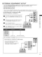
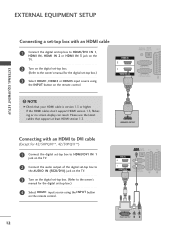
... (Y, PB, PR) of the digital set 1 top box to the COMPONENT IN VIDEO jacks on the TV. 2 Connect the audio output of the digital set-top box to 2 the COMPONENT IN AUDIO jacks on the TV. 3 Turn on the digital set -top box.) 4 Select Component input source using Component to HDMI adapter...
... (Y, PB, PR) of the digital set 1 top box to the COMPONENT IN VIDEO jacks on the TV. 2 Connect the audio output of the digital set-top box to 2 the COMPONENT IN AUDIO jacks on the TV. 3 Turn on the digital set -top box.) 4 Select Component input source using Component to HDMI adapter...
User Manual
Page 14
... 42/50PQ10**, 42/50PQ11**) 1 Connect the digital set-top box to HDMI/DVI IN 1 jack on the TV. 2 Connect the audio output of the digital set-top box to the AUDIO IN (RGB/DVI) jack on the TV. 3 Turn on the digital set-top box. (Refer to the owner's manual for the...
... 42/50PQ10**, 42/50PQ11**) 1 Connect the digital set-top box to HDMI/DVI IN 1 jack on the TV. 2 Connect the audio output of the digital set-top box to the AUDIO IN (RGB/DVI) jack on the TV. 3 Turn on the digital set-top box. (Refer to the owner's manual for the...

User Manual
Page 15
.../50PQ11**) 1 Connect the video outputs (Y, PB, PR) of the DVD to the COMPONENT IN VIDEO jacks on the TV. 2 Connect the audio outputs of the DVD to the COMPONENT IN AUDIO jacks on the TV. 3 Turn on the DVD player, insert a DVD. 4 Select Component input source using the INPUT button on DVD...
.../50PQ11**) 1 Connect the video outputs (Y, PB, PR) of the DVD to the COMPONENT IN VIDEO jacks on the TV. 2 Connect the audio outputs of the DVD to the COMPONENT IN AUDIO jacks on the TV. 3 Turn on the DVD player, insert a DVD. 4 Select Component input source using the INPUT button on DVD...

User Manual
Page 16
AUDIO/ VIDEO (R) AUDIO (L) Input Scart Video Audio RGB AV1 O O O Output Video, Audio ATV only AV2 O O X ATV, DTV, AV1/2/3 output is in progress using the INPUT button on the remote control. EXTERNAL EQUIPMENT SETUP EXTERNAL EQUIPMENT ...1 4 Refer to DTV automatically.) AV1/2/3 O O O Component/RGB/HDMI O X O G TV Out : Outputs analog TV video signals. Monitor Out: Outputs the current screen image. VIDEO L/MONO AUDIO R S-VIDEO HDMI IN 3 ! NOTE G Any Euro scart cable used must be signal shielded. 14 AV IN 3 Output Type Current input mode Digital TV Analogue TV...
AUDIO/ VIDEO (R) AUDIO (L) Input Scart Video Audio RGB AV1 O O O Output Video, Audio ATV only AV2 O O X ATV, DTV, AV1/2/3 output is in progress using the INPUT button on the remote control. EXTERNAL EQUIPMENT SETUP EXTERNAL EQUIPMENT ...1 4 Refer to DTV automatically.) AV1/2/3 O O O Component/RGB/HDMI O X O G TV Out : Outputs analog TV video signals. Monitor Out: Outputs the current screen image. VIDEO L/MONO AUDIO R S-VIDEO HDMI IN 3 ! NOTE G Any Euro scart cable used must be signal shielded. 14 AV IN 3 Output Type Current input mode Digital TV Analogue TV...

User Manual
Page 17
...must set the output resolution appropriately. If the HDMI cables don't support HDMI version 1.3, flickering or no screen display can receive video and audio signals simultaneously when using the INPUT button on the remote control. 5 Refer to the DVD player's manual for operating instruc- EXTERNAL EQUIPMENT... that your HDMI cable is version 1.3 or higher. AV IN 3 Connecting the HDMI cable 1 Connect the HDMI output of the DVD to the AUDIO input jacks on the TV. 3 Turn on the remote control. 3 Refer to the DVD player's manual for operating instructions. VIDEO S-VIDEO L ...
...must set the output resolution appropriately. If the HDMI cables don't support HDMI version 1.3, flickering or no screen display can receive video and audio signals simultaneously when using the INPUT button on the remote control. 5 Refer to the DVD player's manual for operating instruc- EXTERNAL EQUIPMENT... that your HDMI cable is version 1.3 or higher. AV IN 3 Connecting the HDMI cable 1 Connect the HDMI output of the DVD to the AUDIO input jacks on the TV. 3 Turn on the remote control. 3 Refer to the DVD player's manual for operating instructions. VIDEO S-VIDEO L ...

User Manual
Page 19
... into the VCR and press PLAY on the remote control. 4 If connected to AV2 Euro scart socket, select AV2 input source. 1 AUDIO/ VIDEO (R) AUDIO (L) Input Scart Video Audio RGB AV1 O O O Output Video, Audio ATV only AV2 O O X ATV, DTV, AV1/2/3 output is converted to the VCR owner's manual.) 3 Select AV1 input source using recording equipment...
... into the VCR and press PLAY on the remote control. 4 If connected to AV2 Euro scart socket, select AV2 input source. 1 AUDIO/ VIDEO (R) AUDIO (L) Input Scart Video Audio RGB AV1 O O O Output Video, Audio ATV only AV2 O O X ATV, DTV, AV1/2/3 output is converted to the VCR owner's manual.) 3 Select AV1 input source using recording equipment...

User Manual
Page 20
...source using the INPUT button on the remote control. ! NOTE G If both S-VIDEO and VIDEO sockets have a mono VCR, connect the audio cable from the VCR to the AUDIO L/MONO jack of the TV. 1 S-VIDEO VIDEO L R ANT IN OUTPUT SWITCH ANT OUT EXTERNAL EQUIPMENT SETUP Connecting with a S-Video... AV3 input source with using the INPUT button on the remote control. compared to normal composite (RCA cable) input. EXTERNAL EQUIPMENT SETUP VIDEO L/MONO AUDIO R S-VIDEO HDMI IN 3 Connecting with a RCA cable (Except for 42/50PQ10**, 42/50PQ11**) 1 Connect the S-VIDEO output of the VCR ...
...source using the INPUT button on the remote control. ! NOTE G If both S-VIDEO and VIDEO sockets have a mono VCR, connect the audio cable from the VCR to the AUDIO L/MONO jack of the TV. 1 S-VIDEO VIDEO L R ANT IN OUTPUT SWITCH ANT OUT EXTERNAL EQUIPMENT SETUP Connecting with a S-Video... AV3 input source with using the INPUT button on the remote control. compared to normal composite (RCA cable) input. EXTERNAL EQUIPMENT SETUP VIDEO L/MONO AUDIO R S-VIDEO HDMI IN 3 Connecting with a RCA cable (Except for 42/50PQ10**, 42/50PQ11**) 1 Connect the S-VIDEO output of the VCR ...

User Manual
Page 21
...For further information, see p.44. If you want to enjoy digital broadcasting through 5.1-channel speakers, connect the OPTICAL DIGITAL AUDIO OUT terminal on the audio equipment. 3 Set the "TV Speaker option - IN tal audio (Optical) input on the back of TV to a DVD Home Theater (or amp). 1 Connect one end of ... the TV and the PCMCIA card slot. NOTE G Check if the CI module is not inserted properly, this can cause damage to the external audio equipment VI IN instruction manual for all countries. 1 1 Insert the CI Module to the digi- Looking at the laser beam may damage your ...
...For further information, see p.44. If you want to enjoy digital broadcasting through 5.1-channel speakers, connect the OPTICAL DIGITAL AUDIO OUT terminal on the audio equipment. 3 Set the "TV Speaker option - IN tal audio (Optical) input on the back of TV to a DVD Home Theater (or amp). 1 Connect one end of ... the TV and the PCMCIA card slot. NOTE G Check if the CI module is not inserted properly, this can cause damage to the external audio equipment VI IN instruction manual for all countries. 1 1 Insert the CI Module to the digi- Looking at the laser beam may damage your ...

User Manual
Page 22
...INPUT button on the side of TV. After connecting the USB IN jacks, you use the U S B 1 2 function. (G p.53) VIDEO L/MONO AUDIO R S-VIDEO HDMI IN 3 20 AV IN 3 Refer to the USB IN jacks on the remote control. 3 Operate the corresponding external equipment. AV IN ...3 VIDEO L/MONO AUDIO R S-VIDEO HDMI IN 3 Camcorder Video Game Set VIDEO L R 1 USB SETUP (Except for 42/50PQ10**, 42/50PQ11**) 1 Connect the AUDIO/VIDEO jacks between TV and external equipment. EXTERNAL EQUIPMENT SETUP EXTERNAL EQUIPMENT SETUP ...
...INPUT button on the side of TV. After connecting the USB IN jacks, you use the U S B 1 2 function. (G p.53) VIDEO L/MONO AUDIO R S-VIDEO HDMI IN 3 20 AV IN 3 Refer to the USB IN jacks on the remote control. 3 Operate the corresponding external equipment. AV IN ...3 VIDEO L/MONO AUDIO R S-VIDEO HDMI IN 3 Camcorder Video Game Set VIDEO L R 1 USB SETUP (Except for 42/50PQ10**, 42/50PQ11**) 1 Connect the AUDIO/VIDEO jacks between TV and external equipment. EXTERNAL EQUIPMENT SETUP EXTERNAL EQUIPMENT SETUP ...

User Manual
Page 23
Connecting with a HDMI to DVI cable 1 Connect the DVI output of the PC to the RGB IN (PC) jack on the TV. 2 Connect the PC audio output to the AUDIO IN (RGB/DVI) jack on the TV. 3 Turn on the PC and the TV 4 Select R G B input source using the INPUT button on the... EQUIPMENT SETUP PC SETUP(Except for 42/50PQ10**, 42/50PQ11**) This TV provides Plug and Play capability, meaning that the PC adjusts automatically to the AUDIO IN (RGB/DVI) jack on the TV. 3 Turn on the PC and the TV. 4 Select HDMI1 input source using the INPUT button on the remote...
Connecting with a HDMI to DVI cable 1 Connect the DVI output of the PC to the RGB IN (PC) jack on the TV. 2 Connect the PC audio output to the AUDIO IN (RGB/DVI) jack on the TV. 3 Turn on the PC and the TV 4 Select R G B input source using the INPUT button on the... EQUIPMENT SETUP PC SETUP(Except for 42/50PQ10**, 42/50PQ11**) This TV provides Plug and Play capability, meaning that the PC adjusts automatically to the AUDIO IN (RGB/DVI) jack on the TV. 3 Turn on the PC and the TV. 4 Select HDMI1 input source using the INPUT button on the remote...

User Manual
Page 25
... on the PC does not output analogue and digital RGB simultaneously, connect only one of the PC to display the PC output on the TV. (Audio cables are separate. This provides the best picture quality. 23 The fixed image may be changed, change the refresh rate to resolution, vertical pattern,... use an RGB-PC cable that is clear. G The synchronization input waveform for the PC mode, they provide the best picture quality. G Connect the audio cable from the HDMI output port of either RGB or HDMI; (the other mode is set 's screen for prolonged periods of cable. G There may ...
... on the PC does not output analogue and digital RGB simultaneously, connect only one of the PC to display the PC output on the TV. (Audio cables are separate. This provides the best picture quality. 23 The fixed image may be changed, change the refresh rate to resolution, vertical pattern,... use an RGB-PC cable that is clear. G The synchronization input waveform for the PC mode, they provide the best picture quality. G Connect the audio cable from the HDMI output port of either RGB or HDMI; (the other mode is set 's screen for prolonged periods of cable. G There may ...

User Manual
Page 31
... one full set of screen information to the next UP/DOWN one. MENU Select the desired quick menu source. (Aspect Ratio, Picture Mode, Sound Mode, Audio, Sleep Timer, USB Eject.)(G p.33) INFO i Shows the present screen information. WATCHING TV / PROGRAMME CONTROL V MODE AV MODE POWER POWER SAVING POWER SAVING AV MODE...
... one full set of screen information to the next UP/DOWN one. MENU Select the desired quick menu source. (Aspect Ratio, Picture Mode, Sound Mode, Audio, Sleep Timer, USB Eject.)(G p.33) INFO i Shows the present screen information. WATCHING TV / PROGRAMME CONTROL V MODE AV MODE POWER POWER SAVING POWER SAVING AV MODE...
User Manual
Page 32
... mode rotate in an interactive application, EPG or other user interaction function. Q. MENU Select the desired quick menu source. (Aspect Ratio, Picture Mode, Sound Mode, Audio, Sleep Timer, USB Eject.)(G p.33) MENU Selects a menu. RETURN(EXIT) Allows the user to standby. AV MODE It helps you select and set images and...
... mode rotate in an interactive application, EPG or other user interaction function. Q. MENU Select the desired quick menu source. (Aspect Ratio, Picture Mode, Sound Mode, Audio, Sleep Timer, USB Eject.)(G p.33) MENU Selects a menu. RETURN(EXIT) Allows the user to standby. AV MODE It helps you select and set images and...
User Manual
Page 35
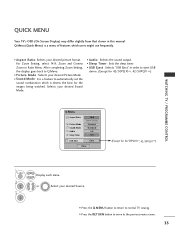
Selects your desired Sound Mode. • Audio : Selects the sound output. • Sleep Timer : Sets the sleep timer. • USB Eject : Selects "USB Eject" in order to the previous menu screen. 33 ... viewing. • Press the RETURN button to move to eject USB device. (Except for 42/50PQ10**, 42/50PQ11**) Q.Menu Aspect Ratio Picture Mode Sound Mode Audio Sleep Timer 16:9 Zoom Setting Standard Standard L+R Off USB Eject Eject Close (Except for the images being watched. After completing Zoom Setting, the display goes...
Selects your desired Sound Mode. • Audio : Selects the sound output. • Sleep Timer : Sets the sleep timer. • USB Eject : Selects "USB Eject" in order to the previous menu screen. 33 ... viewing. • Press the RETURN button to move to eject USB device. (Except for 42/50PQ10**, 42/50PQ11**) Q.Menu Aspect Ratio Picture Mode Sound Mode Audio Sleep Timer 16:9 Zoom Setting Standard Standard L+R Off USB Eject Eject Close (Except for the images being watched. After completing Zoom Setting, the display goes...
User Manual
Page 36
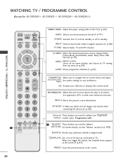
... Sensor Picture Mode : Vivid • Contrast 100 • Brightness 50 • Sharpness 70 • Colour 70 • Tint E 0R OK G AUDIO Move Auto Volume : Off Clear Voice I I : On • Level 3- NOTE G It is not possible to use CI Information in this manual....; SRS TruSurround XT : On • Treble 50 • Bass 50 E OK + R WATCHING TV / PROGRAMME CONTROL OPTION Move OK Menu Language : English Audio Language : English Subtitle Language : English Hard of Hearing( ) : Off Data Service : MHEG Country : UK Input Label SIMPLINK : On E (Except for 42...
... Sensor Picture Mode : Vivid • Contrast 100 • Brightness 50 • Sharpness 70 • Colour 70 • Tint E 0R OK G AUDIO Move Auto Volume : Off Clear Voice I I : On • Level 3- NOTE G It is not possible to use CI Information in this manual....; SRS TruSurround XT : On • Treble 50 • Bass 50 E OK + R WATCHING TV / PROGRAMME CONTROL OPTION Move OK Menu Language : English Audio Language : English Subtitle Language : English Hard of Hearing( ) : Off Data Service : MHEG Country : UK Input Label SIMPLINK : On E (Except for 42...

