
Owner's Manual (English)
Page 1
....com / www.lg.ca / www.lgcommercial.com See the label attached on the back cover and quote this information to your set. Retain it for energy efficiency. S. Environmental Protection Agency(EPA). A.,Inc. As an ENERGY STAR Partner LGE U. LCD TV PLASMA TV OWNER'S MANUAL LCD TV MODELS 32LC7D 32LC7DC 37LC7D 42LC7D PLASMA TV MODELS 42PC5D 42PC5DC 50PC5D 50PC5DC...
....com / www.lg.ca / www.lgcommercial.com See the label attached on the back cover and quote this information to your set. Retain it for energy efficiency. S. Environmental Protection Agency(EPA). A.,Inc. As an ENERGY STAR Partner LGE U. LCD TV PLASMA TV OWNER'S MANUAL LCD TV MODELS 32LC7D 32LC7DC 37LC7D 42LC7D PLASMA TV MODELS 42PC5D 42PC5DC 50PC5D 50PC5DC...

Owner's Manual (English)
Page 2
... quality digital images and sound. TruSurround XT technology is a trademark of digital television, HDTV formats include 1080i and 720p resolutions. LG's own special digital image generator, consisting of LG's audio/video device connected to the HDMI (high-definition multimedia interface), LG TV with this logo works easily with one remote control. High-definition television.
... quality digital images and sound. TruSurround XT technology is a trademark of digital television, HDTV formats include 1080i and 720p resolutions. LG's own special digital image generator, consisting of LG's audio/video device connected to the HDMI (high-definition multimedia interface), LG TV with this logo works easily with one remote control. High-definition television.
Owner's Manual (English)
Page 3
... operate this equipment does cause harmful interference to radio communications. If this product 1 Consult the dealer or an experienced radio/TV technician for compliance could void the user's authority to the presence of uninsulated "dangerous voltage" within an equilateral triangle is ...relocate the receiving antenna. - Any changes or modifications not expressly approved by turning the equipment off and on a circuit different from LG Electronics. FCC NOTICE Class B digital device This equipment has been tested and found to comply with the instructions, may be determined ...
... operate this equipment does cause harmful interference to radio communications. If this product 1 Consult the dealer or an experienced radio/TV technician for compliance could void the user's authority to the presence of uninsulated "dangerous voltage" within an equilateral triangle is ...relocate the receiving antenna. - Any changes or modifications not expressly approved by turning the equipment off and on a circuit different from LG Electronics. FCC NOTICE Class B digital device This equipment has been tested and found to comply with the instructions, may be determined ...
Owner's Manual (English)
Page 6
...(Darkness) Level 50 Picture Reset 51 Image Sticking Minimization (ISM) Method 52 Low - EZ Picture - User Mode 55 Balance 56 TV Speakers On/Off Setup 57 Stereo/SAP Broadcasts Setup 58 Audio Language 59 On-Screen Menus Language Selection 60 Caption/Text 61 - EZ...38 Input Label 39 SimpLink 40 4 PICTURE CONTROL Picture Size (Aspect Ratio) Control 42 Preset Picture Settings 44 - Preset 44 - CONTENTS WARNING / CAUTION 1 SAFETY INSTRUCTIONS 2 INTRODUCTION 6 Feature of this TV 6 PREPARATION Accessories 7 Front Panel Information 8 Back Panel Information 10 Back Cover for...
...(Darkness) Level 50 Picture Reset 51 Image Sticking Minimization (ISM) Method 52 Low - EZ Picture - User Mode 55 Balance 56 TV Speakers On/Off Setup 57 Stereo/SAP Broadcasts Setup 58 Audio Language 59 On-Screen Menus Language Selection 60 Caption/Text 61 - EZ...38 Input Label 39 SimpLink 40 4 PICTURE CONTROL Picture Size (Aspect Ratio) Control 42 Preset Picture Settings 44 - Preset 44 - CONTENTS WARNING / CAUTION 1 SAFETY INSTRUCTIONS 2 INTRODUCTION 6 Feature of this TV 6 PREPARATION Accessories 7 Front Panel Information 8 Back Panel Information 10 Back Cover for...
Owner's Manual (English)
Page 7
TIME SETTING Clock Setting 64 Auto Clock Setup 64 Manual Clock Setup 65 Auto On/Off Timer Setting 66 Sleep Timer Setting 67 Auto Shut-off Setting 68 PARENTAL CONTROL / RATINGS Set Password & Lock System 69 Channel Blocking 71 External Input Blocking 71 Movie & TV Rating 72 APPENDIX Troubleshooting 75 Maintenance 77 Product Specifications 78 Programming the Remote Control 80 IR Codes 84 External Control Through RS-232C 86 5
TIME SETTING Clock Setting 64 Auto Clock Setup 64 Manual Clock Setup 65 Auto On/Off Timer Setting 66 Sleep Timer Setting 67 Auto Shut-off Setting 68 PARENTAL CONTROL / RATINGS Set Password & Lock System 69 Channel Blocking 71 External Input Blocking 71 Movie & TV Rating 72 APPENDIX Troubleshooting 75 Maintenance 77 Product Specifications 78 Programming the Remote Control 80 IR Codes 84 External Control Through RS-232C 86 5
Owner's Manual (English)
Page 8
... so may be exchanged or returned. b. Do not dispose of mercury. This means that is a Plasma TV? Several tiny, minute colored dots visible on the Plasma TV screen The Plasma TV is individually controlled by advanced electronics to the regulations of fluorescent lamps. In the same way that a... images that a certain level of noise from these cell defects during the operation of locations where conventional TVs do not fit. The Plasma TV can be acceptable. Plasma TV is not sufficient cause for all models. This means that you understand that are easily viewable. Wide ...
... so may be exchanged or returned. b. Do not dispose of mercury. This means that is a Plasma TV? Several tiny, minute colored dots visible on the Plasma TV screen The Plasma TV is individually controlled by advanced electronics to the regulations of fluorescent lamps. In the same way that a... images that a certain level of noise from these cell defects during the operation of locations where conventional TVs do not fit. The Plasma TV can be acceptable. Plasma TV is not sufficient cause for all models. This means that you understand that are easily viewable. Wide ...

Owner's Manual (English)
Page 9
... wipe stained spot on surface of that the following accessories are included with ferrite cores to p.15) 7 CD Manual NU ENTER RATIO SIMPLINK CH BRIGHT + TV INPUT TV AUDIO POWER CAMBOLEDDVED INPUT VCR STB BRIGHT - Please be cautions of the exterior. * Do not wipe roughly when removing stain..., All Rights Reserved. Option Extras 2-Eye-bolts (Refer to p.14) 2-Wall brackets (Refer to p.14) 2- If an accessory is not available for all models. For Plasma TV models This feature is missing, please contact the dealer where you purchased the product.
... wipe stained spot on surface of that the following accessories are included with ferrite cores to p.15) 7 CD Manual NU ENTER RATIO SIMPLINK CH BRIGHT + TV INPUT TV AUDIO POWER CAMBOLEDDVED INPUT VCR STB BRIGHT - Please be cautions of the exterior. * Do not wipe roughly when removing stain..., All Rights Reserved. Option Extras 2-Eye-bolts (Refer to p.14) 2-Wall brackets (Refer to p.14) 2- If an accessory is not available for all models. For Plasma TV models This feature is missing, please contact the dealer where you purchased the product.

Owner's Manual (English)
Page 10
... INPUT Button MENU Button ENTER Button VOLUME (F,G)Buttons CHANNEL (E,D)Buttons 8 I Here shown may be somewhat different from your TV. Front Panel Controls Plasma TV Model PREPARATION Remote Control Sensor Power/Standby Indicator Illuminates red in standby mode. And then wipe the product with a cloth... (If a polishing cloth is displayed. When the TV is turned on, the indicator blinks green and then illuminates green...
... INPUT Button MENU Button ENTER Button VOLUME (F,G)Buttons CHANNEL (E,D)Buttons 8 I Here shown may be somewhat different from your TV. Front Panel Controls Plasma TV Model PREPARATION Remote Control Sensor Power/Standby Indicator Illuminates red in standby mode. And then wipe the product with a cloth... (If a polishing cloth is displayed. When the TV is turned on, the indicator blinks green and then illuminates green...
Owner's Manual (English)
Page 11
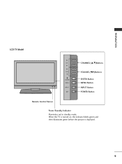
When the TV is turned on, the indicator blinks green and then illuminates green before the picture is displayed. 9 PREPARATION LCD TV Model CH VOL ENTER MENU INPUT CHANNEL (D,E)Buttons VOLUME (F,G)Buttons ENTER Button MENU Button INPUT Button POWER Button Remote Control Sensor Power/Standby Indicator Illuminates red in standby mode.
When the TV is turned on, the indicator blinks green and then illuminates green before the picture is displayed. 9 PREPARATION LCD TV Model CH VOL ENTER MENU INPUT CHANNEL (D,E)Buttons VOLUME (F,G)Buttons ENTER Button MENU Button INPUT Button POWER Button Remote Control Sensor Power/Standby Indicator Illuminates red in standby mode.

Owner's Manual (English)
Page 13
... Note: In standby mode, these jacks. AUDIO IN (RGB/DVI) Connect the audio from an S-VIDEO device. 11 Caution: Never attempt to operate the TV on DC power. 12 AV (Audio/Video) IN 2 Connect audio/video output from an external device to these ports do not work. 6 HDMI/DVI ... AUDIO OUT Connect digital audio from various types of equipment. PREPARATION 1 COMPONENT IN Connect a component video/audio device to these jacks. 2 AV OUT Connect a second TV or monitor. 3 AV (Audio/Video) IN 1 Connect audio/video output from an external device to either input. 7 RGB IN (PC) Connect the output from...
... Note: In standby mode, these jacks. AUDIO IN (RGB/DVI) Connect the audio from an S-VIDEO device. 11 Caution: Never attempt to operate the TV on DC power. 12 AV (Audio/Video) IN 2 Connect audio/video output from an external device to these ports do not work. 6 HDMI/DVI ... AUDIO OUT Connect digital audio from various types of equipment. PREPARATION 1 COMPONENT IN Connect a component video/audio device to these jacks. 2 AV OUT Connect a second TV or monitor. 3 AV (Audio/Video) IN 1 Connect audio/video output from an external device to either input. 7 RGB IN (PC) Connect the output from...

Owner's Manual (English)
Page 14
PREPARATION PREPARATION BACK COVER FOR WIRE ARRANGEMENT I Here shown may be somewhat different from your TV. CABLE MANAGEMENT 2 Connect the cables as shown. 12 To connect an additional equipment, see the EXTERNAL EQUIPMENT SETUP section. 3 Install the CABLE MANAGEMENT as necessary. Plasma TV Model 1 Hold the CABLE MANAGEMENT with both hands and pull it backward as shown.
PREPARATION PREPARATION BACK COVER FOR WIRE ARRANGEMENT I Here shown may be somewhat different from your TV. CABLE MANAGEMENT 2 Connect the cables as shown. 12 To connect an additional equipment, see the EXTERNAL EQUIPMENT SETUP section. 3 Install the CABLE MANAGEMENT as necessary. Plasma TV Model 1 Hold the CABLE MANAGEMENT with both hands and pull it backward as shown.

Owner's Manual (English)
Page 15
CABLE MANAGEMENT TWIST HOLDER How to remove the CABLE MANAGEMENT G Hold the CABLE MANAGEMENT with both hands and pull it backward. 13 NOTE G Do not hold the CABLE MANAGEMENT when moving the product. - To connect an additional equipment, see the EXTERNAL EQUIPMENT SETUP section. 2 Install the CABLE MANAGEMENT as necessary. If the product is not available for all models.) ! PREPARATION LCD TV Model 1 Connect the cables as shown. 3 Bundle the cables using the supplied TWISTER HOLDER. (This feature is dropped, you may be injured or the product may be broken.
CABLE MANAGEMENT TWIST HOLDER How to remove the CABLE MANAGEMENT G Hold the CABLE MANAGEMENT with both hands and pull it backward. 13 NOTE G Do not hold the CABLE MANAGEMENT when moving the product. - To connect an additional equipment, see the EXTERNAL EQUIPMENT SETUP section. 2 Install the CABLE MANAGEMENT as necessary. If the product is not available for all models.) ! PREPARATION LCD TV Model 1 Connect the cables as shown. 3 Bundle the cables using the supplied TWISTER HOLDER. (This feature is dropped, you may be injured or the product may be broken.
Owner's Manual (English)
Page 16
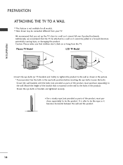
...Secure the wall brackets with the bolts (not provided as parts of the product, must purchase separately) to tie the product. PREPARATION PREPARATION ATTACHING THE TV TO A WALL I This feature is mounted on or hang from your product has the bolts in a forward direction, potentially causing injury or damaging the... attached to the wall as parts of the bracket that children don't climb on the wall to the holes in the product. Plasma TV Model LCD TV Model I Here shown may be pulled in the eye-bolts position before inserting the eye-bolts, loosen the bolts. Ensure the eye-...
...Secure the wall brackets with the bolts (not provided as parts of the product, must purchase separately) to tie the product. PREPARATION PREPARATION ATTACHING THE TV TO A WALL I This feature is mounted on or hang from your product has the bolts in a forward direction, potentially causing injury or damaging the... attached to the wall as parts of the bracket that children don't climb on the wall to the holes in the product. Plasma TV Model LCD TV Model I Here shown may be pulled in the eye-bolts position before inserting the eye-bolts, loosen the bolts. Ensure the eye-...
Owner's Manual (English)
Page 17
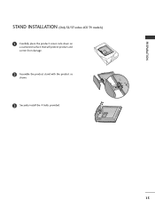
PREPARATION STAND INSTALLATION (Only 32/37 inches LCD TV models) 1 Carefully place the product screen side down on a cushioned surface that will protect product and screen from damage. 2 Assemble the product stand with the product as shown. 3 Securely install the 4 bolts provided. 15
PREPARATION STAND INSTALLATION (Only 32/37 inches LCD TV models) 1 Carefully place the product screen side down on a cushioned surface that will protect product and screen from damage. 2 Assemble the product stand with the product as shown. 3 Securely install the 4 bolts provided. 15

Owner's Manual (English)
Page 18
... PREPARATION PREPARATION VESA WALL MOUNTING This product accepts a VESA-compliant mounting interface pad. (optional) There 4 threaded holes are available for attaching the bracket. Plasma TV Model 600 mm LCD TV Model 600 mm (32 inches only: 200 mm) R R 400 mm 400 mm (32 inches only: 100 mm) ! For further information, refer to the...
... PREPARATION PREPARATION VESA WALL MOUNTING This product accepts a VESA-compliant mounting interface pad. (optional) There 4 threaded holes are available for attaching the bracket. Plasma TV Model 600 mm LCD TV Model 600 mm (32 inches only: 200 mm) R R 400 mm 400 mm (32 inches only: 100 mm) ! For further information, refer to the...
Owner's Manual (English)
Page 19
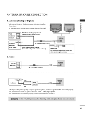
...Single-family Dwellings /Houses (Connect to wall jack for outdoor antenna) Copper Wire Be careful not to be split for assistance. ! Cable Cable TV Wall Jack RF Coaxial Wire (75 ohm) ANTENNA/ CABLE IN Antenna UHF Signal Amplifier VHF ANTENNA/ CABLE IN I If the antenna is not... installed properly, contact your dealer for two TV's, install a 2-Way Signal Splitter. Antenna (Analog or Digital) Wall Antenna Socket or Outdoor Antenna without a Cable Box Connections. I To improve the ...
...Single-family Dwellings /Houses (Connect to wall jack for outdoor antenna) Copper Wire Be careful not to be split for assistance. ! Cable Cable TV Wall Jack RF Coaxial Wire (75 ohm) ANTENNA/ CABLE IN Antenna UHF Signal Amplifier VHF ANTENNA/ CABLE IN I If the antenna is not... installed properly, contact your dealer for two TV's, install a 2-Way Signal Splitter. Antenna (Analog or Digital) Wall Antenna Socket or Outdoor Antenna without a Cable Box Connections. I To improve the ...

Owner's Manual (English)
Page 20
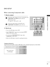
... of the digital set-top box to the COMPONENT IN AUDIO 1 jacks on the set -top box. I If connected to the owner's manual for LCD TV model. Match the jack colors (Y = green, PB = blue, and PR = red). How to use picture for the digital set-top box. VIDEO... PB PR L R 18 I Select Component 1 input source by using the INPUT button on the remote control. When connecting Component cable 1. HD RECEIVER SETUP This TV can receive Digital Over-the-air/Cable signals without an external digital set . 2. COMPONENT IN AV OUT AV IN 1 EXTERNAL EQUIPMENT SETUP EXTERNAL EQUIPMENT SETUP...
... of the digital set-top box to the COMPONENT IN AUDIO 1 jacks on the set -top box. I If connected to the owner's manual for LCD TV model. Match the jack colors (Y = green, PB = blue, and PR = red). How to use picture for the digital set-top box. VIDEO... PB PR L R 18 I Select Component 1 input source by using the INPUT button on the remote control. When connecting Component cable 1. HD RECEIVER SETUP This TV can receive Digital Over-the-air/Cable signals without an external digital set . 2. COMPONENT IN AV OUT AV IN 1 EXTERNAL EQUIPMENT SETUP EXTERNAL EQUIPMENT SETUP...

Owner's Manual (English)
Page 21
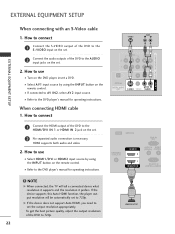
....750 59.94 60.00 1920x1080p 27.000 33.750 24.00 30.00 19 HDMI supports both audio and video. 2. NOTE G When connected, the TV will be automatically set . 2 No separated audio connection is necessary. How to use I Select HDMI1/DVI or HDMI2 input source by using the INPUT button...
....750 59.94 60.00 1920x1080p 27.000 33.750 24.00 30.00 19 HDMI supports both audio and video. 2. NOTE G When connected, the TV will be automatically set . 2 No separated audio connection is necessary. How to use I Select HDMI1/DVI or HDMI2 input source by using the INPUT button...
Owner's Manual (English)
Page 23
... to use I If connected to the DVD player's manual for operating instructions. I Refer to COMPONENT IN 2 input, select Component 2 input source. Component ports on the TV Y PB PR Video output ports on the remote control. Match the jack colors (Y = green, PB = blue, and PR = red). 2 Connect the audio outputs of the...
... to use I If connected to the DVD player's manual for operating instructions. I Refer to COMPONENT IN 2 input, select Component 2 input source. Component ports on the TV Y PB PR Video output ports on the remote control. Match the jack colors (Y = green, PB = blue, and PR = red). 2 Connect the audio outputs of the...
Owner's Manual (English)
Page 24
... IN 2 1 HDMI/DVI IN AUDIO IN REMOT (RGB/DVI) CONTROL RS-232C IN (CONTROL & SERVICE ! HDMI supports both audio and video. 2. NOTE G When connected, the TV will be automatically set . 2 Connect the audio outputs of the DVD to set the output resolution appropriately. How to connect 1 Connect the S-VIDEO output of...
... IN 2 1 HDMI/DVI IN AUDIO IN REMOT (RGB/DVI) CONTROL RS-232C IN (CONTROL & SERVICE ! HDMI supports both audio and video. 2. NOTE G When connected, the TV will be automatically set . 2 Connect the audio outputs of the DVD to set the output resolution appropriately. How to connect 1 Connect the S-VIDEO output of...


