

Owner's Manual
Page 1
.... As an ENERGY STAR Partner LGE U. Please read this information to your set . LCD TV MODELS: 32LC2D 32LC2DU 37LC2D 42LC2D PLASMA TV MODELS: 42PC3D 42PC3DC 42PC3DV 50PC3D 60PC1D OWNER'S MANUAL Internet Home Page : http://www.lge.com http://www.lg.ca ENERGYSTAR is a set of the set . A.,Inc. Record model number and serial number...
.... As an ENERGY STAR Partner LGE U. Please read this information to your set . LCD TV MODELS: 32LC2D 32LC2DU 37LC2D 42LC2D PLASMA TV MODELS: 42PC3D 42PC3DC 42PC3DV 50PC3D 60PC1D OWNER'S MANUAL Internet Home Page : http://www.lge.com http://www.lg.ca ENERGYSTAR is a set of the set . A.,Inc. Record model number and serial number...

Owner's Manual
Page 2
...Unauthorized modification could void the user's authority to correct the interference by turning the equipment off and on a circuit different from LG Electronics Corporation. Reorient or relocate the receiving antenna. - NO USER SERVICEABLE PARTS INSIDE. REFER TO QUALIFIED SERVICE PERSONNEL. CAUTION: ...attempt to which can radiate radio frequency energy and, if not installed and used in a residential installation. NOTE TO CABLE/TV INSTALLER: This reminder is no guarantee that interference will not occur in particular, specifies that to modify this product. REGULATORY ...
...Unauthorized modification could void the user's authority to correct the interference by turning the equipment off and on a circuit different from LG Electronics Corporation. Reorient or relocate the receiving antenna. - NO USER SERVICEABLE PARTS INSIDE. REFER TO QUALIFIED SERVICE PERSONNEL. CAUTION: ...attempt to which can radiate radio frequency energy and, if not installed and used in a residential installation. NOTE TO CABLE/TV INSTALLER: This reminder is no guarantee that interference will not occur in particular, specifies that to modify this product. REGULATORY ...

Owner's Manual
Page 4
...servicer. Periodically examine the cord of this product must remain redily operable. Pay particular attention to be carried out in this product with TV. - On Disposal a. DISCONNECTING DEVICE FROM MAINS Main plug is , a single outlet circuit which powers only that is the disconnecting ...use caution when moving the cart / apparatus combination to qualified service personnel. Protect the power cord from tip-over. 14. If the TV feels cold to the touch, there may produce some temporary distortion effects on the monitor's performance. - Disposal of your finger(s) against it...
...servicer. Periodically examine the cord of this product must remain redily operable. Pay particular attention to be carried out in this product with TV. - On Disposal a. DISCONNECTING DEVICE FROM MAINS Main plug is , a single outlet circuit which powers only that is the disconnecting ...use caution when moving the cart / apparatus combination to qualified service personnel. Protect the power cord from tip-over. 14. If the TV feels cold to the touch, there may produce some temporary distortion effects on the monitor's performance. - Disposal of your finger(s) against it...
Owner's Manual
Page 5
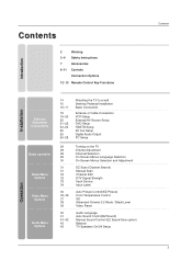
... Audio Menu Options 14 15 16~17 18 19~20 20 21~22 23~24 25 25 26~28 Attaching the TV to a wall Desktop Pedestal Installation Basic Connection Antenna or Cable Connection VCR Setup External AV Source Setup DVD Setup HDSTB... 31 31 32 33 33 34 35 35~36 37 38 39 40 41 41~42 43 43 Turning on the TV Volume Adjustment Channel Selection On Screen Menus Language Selection On Screen Menus Selection and Adjustment EZ Scan (Channel Search) Manual...Level Video Reset Audio Language Auto Sound Control(EZ Sound) Manual Sound Control (EZ Sound-User option) Balance TV Speakers On/Off Setup Operation Contents 5
... Audio Menu Options 14 15 16~17 18 19~20 20 21~22 23~24 25 25 26~28 Attaching the TV to a wall Desktop Pedestal Installation Basic Connection Antenna or Cable Connection VCR Setup External AV Source Setup DVD Setup HDSTB... 31 31 32 33 33 34 35 35~36 37 38 39 40 41 41~42 43 43 Turning on the TV Volume Adjustment Channel Selection On Screen Menus Language Selection On Screen Menus Selection and Adjustment EZ Scan (Channel Search) Manual...Level Video Reset Audio Language Auto Sound Control(EZ Sound) Manual Sound Control (EZ Sound-User option) Balance TV Speakers On/Off Setup Operation Contents 5

Owner's Manual
Page 7
... EZ APM SOUND 0 SAP 8 9 FLASHBK 6 3 FREEZE Remote Control / For 42PC3D/3DC/3DV, For 32/37/42LC2D, 32LC2DU Batteries 50PC3D 42LC2D only 32LC2D/U only 2-Wall brackets 2-eye-bolts 42PC3D/3DC/3DV only 2-bolts (Refer p.14) Option Extras D-sub 15 pin cable Twister Holder 2-TV brackets Arrange the wires 2-Wall brackets with the twister holder...
... EZ APM SOUND 0 SAP 8 9 FLASHBK 6 3 FREEZE Remote Control / For 42PC3D/3DC/3DV, For 32/37/42LC2D, 32LC2DU Batteries 50PC3D 42LC2D only 32LC2D/U only 2-Wall brackets 2-eye-bolts 42PC3D/3DC/3DV only 2-bolts (Refer p.14) Option Extras D-sub 15 pin cable Twister Holder 2-TV brackets Arrange the wires 2-Wall brackets with the twister holder...

Owner's Manual
Page 8
... ENTER Button Button VOLUME (F,G)Buttons CHANNEL (E,D)Buttons Illuminates white when the set is switched on . This picture shown below may be somewhat different from your TV. 42PC3D/3DC/3DV, 50PC3D Remote Control Sensor Power/Standby Indicator • illuminates red in standby mode. This is a simplified representation of front panel. - Introduction Controls...
... ENTER Button Button VOLUME (F,G)Buttons CHANNEL (E,D)Buttons Illuminates white when the set is switched on . This picture shown below may be somewhat different from your TV. 42PC3D/3DC/3DV, 50PC3D Remote Control Sensor Power/Standby Indicator • illuminates red in standby mode. This is a simplified representation of front panel. - Introduction Controls...
Owner's Manual
Page 9
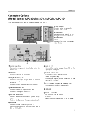
...cable signals to HDMI cable. Caution: Never attempt to 1(DVI) or 2. Note: In standby mode, these ports do notVwIDEOork. 8 Remote Control Port Connect your TV. AUDIO IN (RGB/DVI) Connect the monitor output from a PC to the appropriate input port. 9 RS-232C IN (CONTROL & SERVICE) PORT Connect to the... (VIDEO)signal to these jacks. 7 RGB IN (PC) Connect the monitor output from a PC to the appropriate input port. 2 AV OUT Connect a second TV or monitor. 3 AV (Audio/Video) IN 1 Connect audio/video output from an S-VIDEO device. 4 ANTENNA/CABLE IN Connect over-the air signals to stereo ...
...cable signals to HDMI cable. Caution: Never attempt to 1(DVI) or 2. Note: In standby mode, these ports do notVwIDEOork. 8 Remote Control Port Connect your TV. AUDIO IN (RGB/DVI) Connect the monitor output from a PC to the appropriate input port. 9 RS-232C IN (CONTROL & SERVICE) PORT Connect to the... (VIDEO)signal to these jacks. 7 RGB IN (PC) Connect the monitor output from a PC to the appropriate input port. 2 AV OUT Connect a second TV or monitor. 3 AV (Audio/Video) IN 1 Connect audio/video output from an S-VIDEO device. 4 ANTENNA/CABLE IN Connect over-the air signals to stereo ...
Owner's Manual
Page 10
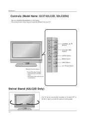
... shown below may be conveniently swivelled on . CHANNEL (D, E) Buttons VOLUME (F,G) Buttons ENTER Button MENU Button INPUT Button (Power) Button Swivel Stand (42LC2D Only) - The TV can be somewhat different from your TV. R 10 CH VOL ENTER MENU R INPUT Remote Control Sensor Power/Standby Indicator • illuminates red in standby mode. • illuminates green...
... shown below may be conveniently swivelled on . CHANNEL (D, E) Buttons VOLUME (F,G) Buttons ENTER Button MENU Button INPUT Button (Power) Button Swivel Stand (42LC2D Only) - The TV can be somewhat different from your TV. R 10 CH VOL ENTER MENU R INPUT Remote Control Sensor Power/Standby Indicator • illuminates red in standby mode. • illuminates green...

Owner's Manual
Page 11
... Connect over-the air signals to this jack. 5 DIGITAL AUDIO OUT Connect digital audio from various types of equipment. Caution: Never attempt to operate the TV on a PC. 10 SERVICE 11 Power Cord Socket For operation with a DVI to these jacks. VIDEO Input Connects the video signal from an external device... power. COMPONENT IN VIDEO AUDIO AV OUT AV IN 1 COMPONENT IN VIDEO AUDIO Introduction S-VIDEO VIDEO ( ) AUDIO AV OUT Connection Options (Model Name: 32/37/42LC2D, 32LC2DU) AV IN 1 S-VIDEO VIDEO ( ) AUDIO - S-VIDEO Input Provides better picture quality than the video input.
... Connect over-the air signals to this jack. 5 DIGITAL AUDIO OUT Connect digital audio from various types of equipment. Caution: Never attempt to operate the TV on a PC. 10 SERVICE 11 Power Cord Socket For operation with a DVI to these jacks. VIDEO Input Connects the video signal from an external device... power. COMPONENT IN VIDEO AUDIO AV OUT AV IN 1 COMPONENT IN VIDEO AUDIO Introduction S-VIDEO VIDEO ( ) AUDIO AV OUT Connection Options (Model Name: 32/37/42LC2D, 32LC2DU) AV IN 1 S-VIDEO VIDEO ( ) AUDIO - S-VIDEO Input Provides better picture quality than the video input.
Owner's Manual
Page 12
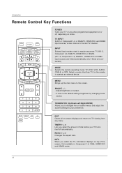
... itself off , depending on -screen menus and adjust the system settings to operate an external device. Introduction Remote Control Key Functions TV INPUT POWER TV AUDIO DVD MODE CABLE INPUT VCR STB BRIGHT - THUMBSTICK (Up/Down/Left/Right/ENTER) Allows you to the screen. MENU BRIGHT + ...POWER Turns your preference. MENU Brings up the main menu to navigate the on mode. TIMER G p.45 Lets you watch the TV, information displays on screen. - Not available in regular sequence: TV, AV1-2, Component 1-2, RGB-PC, HDMI1/DVI or HDMI2. (AV 1-2, Component 1-2, RGB-PC , HDMI1/DVI or HDMI2 ...
... itself off , depending on -screen menus and adjust the system settings to operate an external device. Introduction Remote Control Key Functions TV INPUT POWER TV AUDIO DVD MODE CABLE INPUT VCR STB BRIGHT - THUMBSTICK (Up/Down/Left/Right/ENTER) Allows you to the screen. MENU BRIGHT + ...POWER Turns your preference. MENU Brings up the main menu to navigate the on mode. TIMER G p.45 Lets you watch the TV, information displays on screen. - Not available in regular sequence: TV, AV1-2, Component 1-2, RGB-PC, HDMI1/DVI or HDMI2. (AV 1-2, Component 1-2, RGB-PC , HDMI1/DVI or HDMI2 ...
Owner's Manual
Page 13
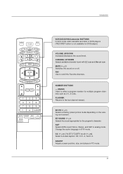
... G p.48 (*In DTV/CADTV mode G p.48) Select a closed caption: Off, CC1~4, Text1~4. SAP Selects MTS sound: Mono, Stereo, and SAP in DTV mode. Introduction TV INPUT POWER TV AUDIO DVD MODE CABLE INPUT VCR STB BRIGHT - VOLUME UP/DOWN Increases/decreases the sound level. FAV Use to scroll the Favorite channels. ADJUST...
... G p.48 (*In DTV/CADTV mode G p.48) Select a closed caption: Off, CC1~4, Text1~4. SAP Selects MTS sound: Mono, Stereo, and SAP in DTV mode. Introduction TV INPUT POWER TV AUDIO DVD MODE CABLE INPUT VCR STB BRIGHT - VOLUME UP/DOWN Increases/decreases the sound level. FAV Use to scroll the Favorite channels. ADJUST...
Owner's Manual
Page 14
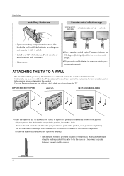
... that is safer to preserve environment. Additionally, we recommend that children don't climb on or hang from the TV. 42PC3D/3DC/3DV, 50PC3D 60PC1D 32/37/42LC2D, 32LC2DU I Insert the eye-bolts (or TV brackets and bolts) to tighten the product to the wall as parts of the product, must purchase separately) to...
... that is safer to preserve environment. Additionally, we recommend that children don't climb on or hang from the TV. 42PC3D/3DC/3DV, 50PC3D 60PC1D 32/37/42LC2D, 32LC2DU I Insert the eye-bolts (or TV brackets and bolts) to tighten the product to the wall as parts of the product, must purchase separately) to...
Owner's Manual
Page 15
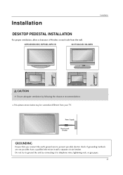
Installation Installation DESKTOP PEDESTAL INSTALLATION For proper ventilation, allow a clearance of 4inches on each side from your TV. I This picture shown below may be somewhat different from the wall. 42PC3D/3DC/3DV, 50PC3D, 60PC1D 32/37/42LC2D, 32LC2DU 4 inches 4 inches 4 inches 4 inches 4 inches 4 inches 4 inches 4 inches CAUTION G Ensure adequate ventilation by connecting it...
Installation Installation DESKTOP PEDESTAL INSTALLATION For proper ventilation, allow a clearance of 4inches on each side from your TV. I This picture shown below may be somewhat different from the wall. 42PC3D/3DC/3DV, 50PC3D, 60PC1D 32/37/42LC2D, 32LC2DU 4 inches 4 inches 4 inches 4 inches 4 inches 4 inches 4 inches 4 inches CAUTION G Ensure adequate ventilation by connecting it...
Owner's Manual
Page 18
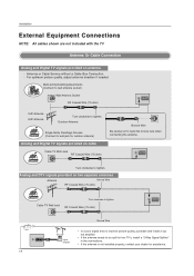
...antenna socket) Wall Antenna Socket RF Coaxial Wire (75 ohm) ANTENNA/ CABLE IN VHF Antenna UHF Antenna Turn clockwise to be split for two TV's, install a "2-Way Signal Splitter" • in the connections. Outdoor Antenna Single-family Dwellings /Houses (Connect to wall jack for assistance....Cable Box Connection. - Installation External Equipment Connections NOTE: All cables shown are not included with the TV Antenna Or Cable Connection Analog and Digital TV signals provided on cable Cable TV Wall Jack RF Coaxial Wire (75 ohm) Bronze Wire Be careful not to bend the bronze wire...
...antenna socket) Wall Antenna Socket RF Coaxial Wire (75 ohm) ANTENNA/ CABLE IN VHF Antenna UHF Antenna Turn clockwise to be split for two TV's, install a "2-Way Signal Splitter" • in the connections. Outdoor Antenna Single-family Dwellings /Houses (Connect to wall jack for assistance....Cable Box Connection. - Installation External Equipment Connections NOTE: All cables shown are not included with the TV Antenna Or Cable Connection Analog and Digital TV signals provided on cable Cable TV Wall Jack RF Coaxial Wire (75 ohm) Bronze Wire Be careful not to bend the bronze wire...
Owner's Manual
Page 19
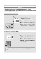
... SWITCH IN 34 VIDEO AUDIO ANT OUT 1 OPTICAL DIGITAL AUDIO ( ) VIDEOS-VIDEO VIDEOAUDIO AUDIO OUT 1 Connect the AUDIO/VIDEO jacks between the VCR and TV. - Match the jack colors (Video = yellow, Audio Left = white, and Audio Right = red) 2 Insert a video tape into the VCR and... press PLAY on the remote control. - To avoid picture noise (interference), leave an adequate distance between TV and VCR. Installation VCR Setup - When connecting with an antenna 2 VCR ANT IN ANT OUT S-VIDEO OUT OUTPUT SWITCH 34 (R) AUDIO (L) IN VIDEO ...
... SWITCH IN 34 VIDEO AUDIO ANT OUT 1 OPTICAL DIGITAL AUDIO ( ) VIDEOS-VIDEO VIDEOAUDIO AUDIO OUT 1 Connect the AUDIO/VIDEO jacks between the VCR and TV. - Match the jack colors (Video = yellow, Audio Left = white, and Audio Right = red) 2 Insert a video tape into the VCR and... press PLAY on the remote control. - To avoid picture noise (interference), leave an adequate distance between TV and VCR. Installation VCR Setup - When connecting with an antenna 2 VCR ANT IN ANT OUT S-VIDEO OUT OUTPUT SWITCH 34 (R) AUDIO (L) IN VIDEO ...

Owner's Manual
Page 20
External AV Source Setup Camcorder Video Game Set 1 L AUDIO R VIDEO 1 Connect the AUDIO/VIDEO jacks between TV and external equipment. If connected to AV IN2, select AV2 input source. Do not connect to both Video and the S-Video cables, only the.... - If connected to AV IN1 input, select AV1 input source. 3 Operate the corresponding external equipment. Refer to external equipment operating guide. • This TV finds the connected input sources automatically for AV1, AV2, Component 1-2, RGB, HDMI1/DVI and HDMI2 sources are connected. 20 The picture quality is improved; In...
External AV Source Setup Camcorder Video Game Set 1 L AUDIO R VIDEO 1 Connect the AUDIO/VIDEO jacks between TV and external equipment. If connected to AV IN2, select AV2 input source. Do not connect to both Video and the S-Video cables, only the.... - If connected to AV IN1 input, select AV1 input source. 3 Operate the corresponding external equipment. Refer to external equipment operating guide. • This TV finds the connected input sources automatically for AV1, AV2, Component 1-2, RGB, HDMI1/DVI and HDMI2 sources are connected. 20 The picture quality is improved; In...

Owner's Manual
Page 21
... DVD to the DVD player's manual for operating instructions. VIDEO AUDIO COMPONENT IN AV OUT AV IN 1 OPTICAL DIGITAL AUDIO OUT S-VIDEO VIDEO ( ) AUDIO • TV can receive the video and audio signal simultaneously with using a HDMI cable. • If the DVD supports Auto HDMI function, the DVD output resolution will...
... DVD to the DVD player's manual for operating instructions. VIDEO AUDIO COMPONENT IN AV OUT AV IN 1 OPTICAL DIGITAL AUDIO OUT S-VIDEO VIDEO ( ) AUDIO • TV can receive the video and audio signal simultaneously with using a HDMI cable. • If the DVD supports Auto HDMI function, the DVD output resolution will...

Owner's Manual
Page 22
... for operating instructions. If connected to COMPONENT IN 2, select Component 2 input source. 5 Refer to the component input ports as shown below. Component ports on the TV Video output ports on the remote control. - Installation When connecting with a component cable DVD B R (R) AUDIO (L) 1 2 VIDEO AUDIO ANTENNA/ CABLE IN HDMI / DVI IN COMPONENT IN...
... for operating instructions. If connected to COMPONENT IN 2, select Component 2 input source. 5 Refer to the component input ports as shown below. Component ports on the TV Video output ports on the remote control. - Installation When connecting with a component cable DVD B R (R) AUDIO (L) 1 2 VIDEO AUDIO ANTENNA/ CABLE IN HDMI / DVI IN COMPONENT IN...
Owner's Manual
Page 23
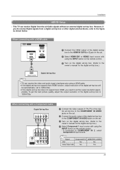
... to 1280x720p. Installation HDSTB Setup - HDMI / DVI IN 3 Turn on the set the output resolution appro- If connected to the figure as shown below. This TV can receive Digital Over-the-air/Cable signals without an external digital set -top box. (Refer to the RS-232C IN owner's manual for the... box.) HDMI-DTV OUTPUT Digital Set-top Box COMPONENT IN AV OUT AV IN 1 RGB IN (PC) AUDIO IN REMOTE (RGB/DVI) CONTROL IN • TV can receive the video and audio signal simultaneously using the INPUT button on the remote control. -
... to 1280x720p. Installation HDSTB Setup - HDMI / DVI IN 3 Turn on the set the output resolution appro- If connected to the figure as shown below. This TV can receive Digital Over-the-air/Cable signals without an external digital set -top box. (Refer to the RS-232C IN owner's manual for the... box.) HDMI-DTV OUTPUT Digital Set-top Box COMPONENT IN AV OUT AV IN 1 RGB IN (PC) AUDIO IN REMOTE (RGB/DVI) CONTROL IN • TV can receive the video and audio signal simultaneously using the INPUT button on the remote control. -
Owner's Manual
Page 25
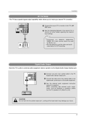
...CAUTION Do not look into the optical output port. When connecting with external audio equipments, such as amplifiers or speakers, please turn the TV speakers off. (Refer to external audio equipment (stereo system) via the Digital Audio Output Optical port. Installation AV Out Setup - ... OPTICAL DIGITAL AUDIO OUT S-VIDEO VIDEO (MONO) AUDIO 1/2 1 Connect one end of an optical cable to the TV Digital Audio Optical Output port. 2 Connect the other end of the second TV or monitor for further details regarding that device's input settings. 1/2 S-VIDEO IN (R) AUDIO (L) VIDEO • ...
...CAUTION Do not look into the optical output port. When connecting with external audio equipments, such as amplifiers or speakers, please turn the TV speakers off. (Refer to external audio equipment (stereo system) via the Digital Audio Output Optical port. Installation AV Out Setup - ... OPTICAL DIGITAL AUDIO OUT S-VIDEO VIDEO (MONO) AUDIO 1/2 1 Connect one end of an optical cable to the TV Digital Audio Optical Output port. 2 Connect the other end of the second TV or monitor for further details regarding that device's input settings. 1/2 S-VIDEO IN (R) AUDIO (L) VIDEO • ...


