
Owner's Manual
Page 5
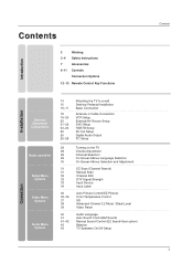
Contents Introduction 2 3~4 7 8~11 Warning Safety Instructions Accessories Controls Connection Options 12~13 Remote Control Key Functions Installation External Equipment Connections Basic operation Setup Menu Options Video Menu Options Audio Menu Options 14 15 16~...) Manual Scan Channel Edit DTV Signal Strength Input Source Input Label Auto Picture Control(EZ Picture) Color Temperature Control XD Advanced-Cinema 3:2 Mode / Black Level Video Reset Audio Language Auto Sound Control(EZ Sound) Manual Sound Control (EZ Sound-User option) Balance TV Speakers On/Off Setup Operation Contents 5
Contents Introduction 2 3~4 7 8~11 Warning Safety Instructions Accessories Controls Connection Options 12~13 Remote Control Key Functions Installation External Equipment Connections Basic operation Setup Menu Options Video Menu Options Audio Menu Options 14 15 16~...) Manual Scan Channel Edit DTV Signal Strength Input Source Input Label Auto Picture Control(EZ Picture) Color Temperature Control XD Advanced-Cinema 3:2 Mode / Black Level Video Reset Audio Language Auto Sound Control(EZ Sound) Manual Sound Control (EZ Sound-User option) Balance TV Speakers On/Off Setup Operation Contents 5

Owner's Manual
Page 7
...+ RATIO TIMER EXIT VOL MUTE CC PAGE INFO 1 FAV 4 7 2 PAGE CH 5 EZ ADJUST PIC EZ APM SOUND 0 SAP 8 9 FLASHBK 6 3 FREEZE Remote Control / For 42PC3D/3DC/3DV, For 32/37/42LC2D, 32LC2DU Batteries 50PC3D 42LC2D only 32LC2D/U only 2-Wall brackets 2-eye-bolts 42PC3D/3DC/3DV only 2-bolts (Refer p.14) Option Extras D-sub 15 pin cable...
...+ RATIO TIMER EXIT VOL MUTE CC PAGE INFO 1 FAV 4 7 2 PAGE CH 5 EZ ADJUST PIC EZ APM SOUND 0 SAP 8 9 FLASHBK 6 3 FREEZE Remote Control / For 42PC3D/3DC/3DV, For 32/37/42LC2D, 32LC2DU Batteries 50PC3D 42LC2D only 32LC2D/U only 2-Wall brackets 2-eye-bolts 42PC3D/3DC/3DV only 2-bolts (Refer p.14) Option Extras D-sub 15 pin cable...

Owner's Manual
Page 8
This picture shown below may be somewhat different from your TV. 42PC3D/3DC/3DV, 50PC3D Remote Control Sensor Power/Standby Indicator • illuminates red in standby mode. Illuminates white when the set is a simplified representation of front panel.... - CH VOL ENTER MENU INPUT CHANNEL (D, E) Buttons VOLUME (F,G) Buttons ENTER Button MENU Button INPUT Button (Power) Button 60PC1D Remote Control Sensor Power Standby Indicator Illuminates red in standby mode. • illuminates green when the set is switched on . This is switched on . 8 ENTER ...
This picture shown below may be somewhat different from your TV. 42PC3D/3DC/3DV, 50PC3D Remote Control Sensor Power/Standby Indicator • illuminates red in standby mode. Illuminates white when the set is a simplified representation of front panel.... - CH VOL ENTER MENU INPUT CHANNEL (D, E) Buttons VOLUME (F,G) Buttons ENTER Button MENU Button INPUT Button (Power) Button 60PC1D Remote Control Sensor Power Standby Indicator Illuminates red in standby mode. • illuminates green when the set is switched on . This is switched on . 8 ENTER ...
Owner's Manual
Page 9
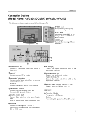
...OUT AV IN 1 COMPONENT IN AV OUT AV IN 1 6 HDMI IN VIDEO AUDIO Connect a HDMI signal to stereo sound from your wired remote control. Or DVI (VIDEO)signal to the RS-232C port on DC power. VIDEO Input Connects the video signal from various types of equipment. Connect.../Video) IN 1 Connect audio/video output from an S-VIDEO device. 4 ANTENNA/CABLE IN Connect over-the air signals to these ports do notVwIDEOork. 8 Remote Control Port Connect your TV. S-VIDEO Connect S-Video out from an external device to this jack. 5 DIGITAL AUDIO OUT Connect digital audio from a 11 video ...
...OUT AV IN 1 COMPONENT IN AV OUT AV IN 1 6 HDMI IN VIDEO AUDIO Connect a HDMI signal to stereo sound from your wired remote control. Or DVI (VIDEO)signal to the RS-232C port on DC power. VIDEO Input Connects the video signal from various types of equipment. Connect.../Video) IN 1 Connect audio/video output from an S-VIDEO device. 4 ANTENNA/CABLE IN Connect over-the air signals to these ports do notVwIDEOork. 8 Remote Control Port Connect your TV. S-VIDEO Connect S-Video out from an external device to this jack. 5 DIGITAL AUDIO OUT Connect digital audio from a 11 video ...
Owner's Manual
Page 10
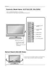
CHANNEL (D, E) Buttons VOLUME (F,G) Buttons ENTER Button MENU Button INPUT Button (Power) Button Swivel Stand (42LC2D Only) - R 10 CH VOL ENTER MENU R INPUT Remote Control Sensor Power/Standby Indicator • illuminates red in standby mode. • illuminates green when the set is a simplified representation of front panel. - This picture shown ...
CHANNEL (D, E) Buttons VOLUME (F,G) Buttons ENTER Button MENU Button INPUT Button (Power) Button Swivel Stand (42LC2D Only) - R 10 CH VOL ENTER MENU R INPUT Remote Control Sensor Power/Standby Indicator • illuminates red in standby mode. • illuminates green when the set is a simplified representation of front panel. - This picture shown ...

Owner's Manual
Page 11
... 3 AV OUT 1 COMPONENT IN Connect a component these ports do not work. 8 Remote Control Port Connect your TV. COMPONENT IN VIDEO AUDIO AV OUT AV IN 1 COMPONENT IN VIDEO AUDIO Introduction S-VIDEO VIDEO ( ) AUDIO AV OUT Connection Options (Model Name: 32/37/42LC2D, 32LC2DU) AV IN 1 S-VIDEO VIDEO ( ) AUDIO - This picture shown below may...
... 3 AV OUT 1 COMPONENT IN Connect a component these ports do not work. 8 Remote Control Port Connect your TV. COMPONENT IN VIDEO AUDIO AV OUT AV IN 1 COMPONENT IN VIDEO AUDIO Introduction S-VIDEO VIDEO ( ) AUDIO AV OUT Connection Options (Model Name: 32/37/42LC2D, 32LC2DU) AV IN 1 S-VIDEO VIDEO ( ) AUDIO - This picture shown below may...
Owner's Manual
Page 12
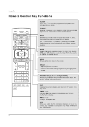
... and HDMI2 mode. 12 INFO When you watch the TV, information displays on screen. - RATIO G p.47 Changes the aspect ratio. Introduction Remote Control Key Functions TV INPUT POWER TV AUDIO DVD MODE CABLE INPUT VCR STB BRIGHT - Adjust brightness on top of time before your preference. MENU ... or HDMI2. (AV 1-2, Component 1-2, RGB-PC , HDMI1/DVI or HDMI2 input sources are linked automatically, only if these are connected.) MODE Selects the remote operating mode: TV, DVD, VCR, AUDIO, CABLE, or STB. TV INPUT In AV1-2, Component 1-2, or RGB-PC, HDMI1/DVI, and HDMI2 input...
... and HDMI2 mode. 12 INFO When you watch the TV, information displays on screen. - RATIO G p.47 Changes the aspect ratio. Introduction Remote Control Key Functions TV INPUT POWER TV AUDIO DVD MODE CABLE INPUT VCR STB BRIGHT - Adjust brightness on top of time before your preference. MENU ... or HDMI2. (AV 1-2, Component 1-2, RGB-PC , HDMI1/DVI or HDMI2 input sources are linked automatically, only if these are connected.) MODE Selects the remote operating mode: TV, DVD, VCR, AUDIO, CABLE, or STB. TV INPUT In AV1-2, Component 1-2, or RGB-PC, HDMI1/DVI, and HDMI2 input...
Owner's Manual
Page 14
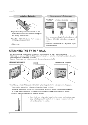
I Use a remote control up the TV close to a wall so it cannot be attached to a wall so... A WALL We recommend that children don't climb on or hang from the TV. 42PC3D/3DC/3DV, 50PC3D 60PC1D 32/37/42LC2D, 32LC2DU I Insert the eye-bolts (or TV brackets and bolts) to tighten the product to 7 meters distance and 30 ...MODE CABLE INPUT VCR STB BRIGHT - It is mounted on the wall to preserve environment. Introduction Installing Batteries Remote control effective range 32/37/42LC2D, 32LC2DU 42PC3D/3DC/3DV, 50PC3D 60PC1D I Open the battery compartment cover on the back side and install ...
I Use a remote control up the TV close to a wall so it cannot be attached to a wall so... A WALL We recommend that children don't climb on or hang from the TV. 42PC3D/3DC/3DV, 50PC3D 60PC1D 32/37/42LC2D, 32LC2DU I Insert the eye-bolts (or TV brackets and bolts) to tighten the product to 7 meters distance and 30 ...MODE CABLE INPUT VCR STB BRIGHT - It is mounted on the wall to preserve environment. Introduction Installing Batteries Remote control effective range 32/37/42LC2D, 32LC2DU 42PC3D/3DC/3DV, 50PC3D 60PC1D I Open the battery compartment cover on the back side and install ...
Owner's Manual
Page 19
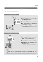
the fixed images on the sides of the screen may remain visible on the remote control. - Match the jack colors (Video = yellow, Audio Left = white, and Audio Right = red) 2 Insert a video tape into the VCR and press PLAY on the VCR. (... VIDEO SERVICE 1 RGB IN (PC) ANTENNA/ CABLSEEIRNVICE HDMI IN 2 1(DVI) AUDIO IN REMOTE (RGB/DVI) CONTROL IN RGBRISN-232C IN ((CPOCN)TROL & SERVICE) AUDIO IN REMOTE (RGB/DVI) CONTROL IN HDMI / DVI IN ANTENNA/ CABLE IN RS-232C IN When connecting with a (CONTROL&SERVICE) RCA cable 1 Connect the RF antenna out socket of the VCR...
the fixed images on the sides of the screen may remain visible on the remote control. - Match the jack colors (Video = yellow, Audio Left = white, and Audio Right = red) 2 Insert a video tape into the VCR and press PLAY on the VCR. (... VIDEO SERVICE 1 RGB IN (PC) ANTENNA/ CABLSEEIRNVICE HDMI IN 2 1(DVI) AUDIO IN REMOTE (RGB/DVI) CONTROL IN RGBRISN-232C IN ((CPOCN)TROL & SERVICE) AUDIO IN REMOTE (RGB/DVI) CONTROL IN HDMI / DVI IN ANTENNA/ CABLE IN RS-232C IN When connecting with a (CONTROL&SERVICE) RCA cable 1 Connect the RF antenna out socket of the VCR...

Owner's Manual
Page 20
... colors (Video = yellow, Audio Left = white, and Audio Right = red). 2 Select AV2 input source with using the INPUT button on the remote control. - The picture quality is improved; If connected to AV IN1 input, select AV1 input source. 3 Operate the corresponding external equipment. If connected to... and press PLAY on the VCR. (Refer to the VCR owner's manual.) 4 Select AV1 input source with using the INPUT button on the remote control. - External AV Source Setup Camcorder Video Game Set 1 L AUDIO R VIDEO 1 Connect the AUDIO/VIDEO jacks between TV and external equipment....
... colors (Video = yellow, Audio Left = white, and Audio Right = red). 2 Select AV2 input source with using the INPUT button on the remote control. - The picture quality is improved; If connected to AV IN1 input, select AV1 input source. 3 Operate the corresponding external equipment. If connected to... and press PLAY on the VCR. (Refer to the VCR owner's manual.) 4 Select AV1 input source with using the INPUT button on the remote control. - External AV Source Setup Camcorder Video Game Set 1 L AUDIO R VIDEO 1 Connect the AUDIO/VIDEO jacks between TV and external equipment....

Owner's Manual
Page 21
... resolution will be automatically set to 1280x720p. • If the DVD does not support Auto HDMI, you need to set . 3 Turn on the remote control. - VIDEO AUDIO COMPONENT IN AV OUT AV IN 1 OPTICAL DIGITAL AUDIO OUT S-VIDEO VIDEO ( ) AUDIO • TV can receive the video ...signal simultaneously with using the INPUT button on the DVD player, insert a DVD. 4 Select AV1 input source with using the INPUT button on the remote control. 3 Refer to the AUDIO input jacks on the set the output resolution appropriately. When connecting with a HDMI cable ANTENNA/ CABLE IN HDMI IN ...
... resolution will be automatically set to 1280x720p. • If the DVD does not support Auto HDMI, you need to set . 3 Turn on the remote control. - VIDEO AUDIO COMPONENT IN AV OUT AV IN 1 OPTICAL DIGITAL AUDIO OUT S-VIDEO VIDEO ( ) AUDIO • TV can receive the video ...signal simultaneously with using the INPUT button on the DVD player, insert a DVD. 4 Select AV1 input source with using the INPUT button on the remote control. 3 Refer to the AUDIO input jacks on the set the output resolution appropriately. When connecting with a HDMI cable ANTENNA/ CABLE IN HDMI IN ...

Owner's Manual
Page 22
Component ports on the TV Video output ports on the remote control. - COMPONENT IN AV OUT AV IN 1 • Component Input ports VIDEO AUDIO To get better picture quality, connect a DVD player to the DVD player's manual ...
Component ports on the TV Video output ports on the remote control. - COMPONENT IN AV OUT AV IN 1 • Component Input ports VIDEO AUDIO To get better picture quality, connect a DVD player to the DVD player's manual ...
Owner's Manual
Page 23
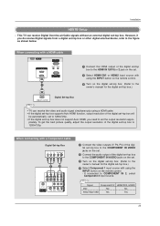
...the digital set-top box.) HDMI-DTV OUTPUT Digital Set-top Box COMPONENT IN AV OUT AV IN 1 RGB IN (PC) AUDIO IN REMOTE (RGB/DVI) CONTROL IN • TV can receive Digital Over-the-air/Cable signals without an external digital set the output resolution appro- Installation HDSTB Setup ...&StER-VtICoE) p box.) 4 Select Component 1 input source with a HDMI cable SERVICE HDMI IN 2 1(DVI) RGB IN (PC) AUDIO IN REMOTE (RGB/DVI) CONTROL IN RS-232C IN (CONTROL & SERVICE) 1 1 Connect the HDMI output of the digital set-top box will be automatically set to 1280x720p. • If the digital set...
...the digital set-top box.) HDMI-DTV OUTPUT Digital Set-top Box COMPONENT IN AV OUT AV IN 1 RGB IN (PC) AUDIO IN REMOTE (RGB/DVI) CONTROL IN • TV can receive Digital Over-the-air/Cable signals without an external digital set the output resolution appro- Installation HDSTB Setup ...&StER-VtICoE) p box.) 4 Select Component 1 input source with a HDMI cable SERVICE HDMI IN 2 1(DVI) RGB IN (PC) AUDIO IN REMOTE (RGB/DVI) CONTROL IN RS-232C IN (CONTROL & SERVICE) 1 1 Connect the HDMI output of the digital set-top box will be automatically set to 1280x720p. • If the digital set...
Owner's Manual
Page 24
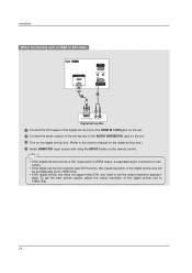
... owner's manual for the d(PCi)gital set-top box.) REMORTEGBAIUNDIO IN CONTROL IN (RGB/DVI) 4 Select HDMI1/DVI input source with a HDMI to DVI cable SERVICE HDMI IN 2 1(DVI) 1 RGB IN (PC) AUDIO IN REMOTE (RGB/DVI) CONTROL IN RS-232C IN (CONTROL & SERVICE) 2 COMPONENT IN AV OUT AV IN 1 1(DVI) ...RS-232C IN (CONTROL & SERVICE) DVI-DTV OUTPUT (R) AUDIO (L) Digital Set-top Box 1 Connect the DVI output of the digital...
... owner's manual for the d(PCi)gital set-top box.) REMORTEGBAIUNDIO IN CONTROL IN (RGB/DVI) 4 Select HDMI1/DVI input source with a HDMI to DVI cable SERVICE HDMI IN 2 1(DVI) 1 RGB IN (PC) AUDIO IN REMOTE (RGB/DVI) CONTROL IN RS-232C IN (CONTROL & SERVICE) 2 COMPONENT IN AV OUT AV IN 1 1(DVI) ...RS-232C IN (CONTROL & SERVICE) DVI-DTV OUTPUT (R) AUDIO (L) Digital Set-top Box 1 Connect the DVI output of the digital...
Owner's Manual
Page 26
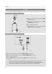
...Turn on the PC and the set. 4 Select RGB-PC input source with using the INPUT button on the remote control. RGB IN (PC) AUDIO IN REMOTE (RGB/DVI) CONTROL IN Installation RS-232C IN (CONTROL & SERVICE) PC Setup - This TV provides Plug and Play capability, meaning that the PC adjusts automatically to... the HDMI IN 1(DVI) jack on the remote control. When connecting with a D-sub 15 pin cable RGB IN (PC) AUDIO IN REMOTE (RGB/DVI) CONTROL IN RS-232C IN (CONTROL & SERVICE) 2 1 1 Connect the RGB output of the PC to the RGB IN (PC...
...Turn on the PC and the set. 4 Select RGB-PC input source with using the INPUT button on the remote control. RGB IN (PC) AUDIO IN REMOTE (RGB/DVI) CONTROL IN Installation RS-232C IN (CONTROL & SERVICE) PC Setup - This TV provides Plug and Play capability, meaning that the PC adjusts automatically to... the HDMI IN 1(DVI) jack on the remote control. When connecting with a D-sub 15 pin cable RGB IN (PC) AUDIO IN REMOTE (RGB/DVI) CONTROL IN RS-232C IN (CONTROL & SERVICE) 2 1 1 Connect the RGB output of the PC to the RGB IN (PC...

Owner's Manual
Page 29
... menus can cancel this function by using the TV, press the POWER button on the remote control. In standby mode to select your language. 1 Press the MENU button and then use D / E button to select the OPTION menu. 2 Press the G button and then ... selected language. When finished using TV INPUT, INPUT button on the TV 1. The TV reverts to standby mode. Operation Operation Basic operation Turning on the remote control. From this moment, the TV switches to standby mode. Select the viewing source by pressing the MUTE or VOL D / E button.
... menus can cancel this function by using the TV, press the POWER button on the remote control. In standby mode to select your language. 1 Press the MENU button and then use D / E button to select the OPTION menu. 2 Press the G button and then ... selected language. When finished using TV INPUT, INPUT button on the TV 1. The TV reverts to standby mode. Operation Operation Basic operation Turning on the remote control. From this moment, the TV switches to standby mode. Select the viewing source by pressing the MUTE or VOL D / E button.

Owner's Manual
Page 32
... then use D / E button to the channel edit screen. - Once a channel is highlighted you can add or delete the channel by toggling each channel on the remote control when a channel is "Favorite List" in gray color. The heart-mark will now see a screen filled with ENTER button. Use the FAV button on or...
... then use D / E button to the channel edit screen. - Once a channel is highlighted you can add or delete the channel by toggling each channel on the remote control when a channel is "Favorite List" in gray color. The heart-mark will now see a screen filled with ENTER button. Use the FAV button on or...
Owner's Manual
Page 52
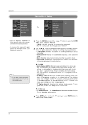
... limit by inputting a new password twice. • Block Channel: Select a channel number that you block certain TV programs intended for mature audiences in '7', '7', '7', '7' on the remote control. 1 Press the MENU button and then use D / E button to choose from watching certain children's TV programs, according to view. The children rating does not apply...
... limit by inputting a new password twice. • Block Channel: Select a channel number that you block certain TV programs intended for mature audiences in '7', '7', '7', '7' on the remote control. 1 Press the MENU button and then use D / E button to choose from watching certain children's TV programs, according to view. The children rating does not apply...
Owner's Manual
Page 54
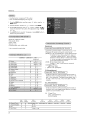
...~ 3 p * (Refer to p.57) q 0 ~ 1 Transmission / Receiving Protocol Transmission [Command1][Command2][ ][Set ID][ ][Data][Cr] * [Command 1]: First command to control the set.(j,k,m or x) * [Command 2]: Second command to control the set. * [Set ID]: You can adjust the set ID to select the SETUP menu. 2. Transmit 'FF' data to select Set ID... is controlled. Volume Control k 07. Key 23. Reference Set ID - ISM Method j 19. Data 1: Illegal Code 2: Not supported function 3: Wait more time COM- Treble k 15. Refer to 'Real Data Mapping'. Aspect Ratio k 04. Remote Control Lock ...
...~ 3 p * (Refer to p.57) q 0 ~ 1 Transmission / Receiving Protocol Transmission [Command1][Command2][ ][Set ID][ ][Data][Cr] * [Command 1]: First command to control the set.(j,k,m or x) * [Command 2]: Second command to control the set. * [Set ID]: You can adjust the set ID to select the SETUP menu. 2. Transmit 'FF' data to select Set ID... is controlled. Volume Control k 07. Key 23. Reference Set ID - ISM Method j 19. Data 1: Illegal Code 2: Not supported function 3: Wait more time COM- Treble k 15. Refer to 'Real Data Mapping'. Aspect Ratio k 04. Remote Control Lock ...
Owner's Manual
Page 55
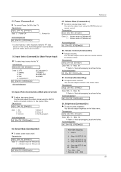
...~ Max : 64 • Refer to 'Real data mapping' as shown below . Screen Mute (Command2:d) G To select screen mute on remote control. Contrast (Command2:g) G To adjust screen contrast. Input Select (Command2:b) (Main Picture Input) G To select input source for the TV. ... R50 55 You can also adjust mute using the RATIO button on ) Acknowledgement [e][ ][Set ID][ ][OK][Data][x] 06. Volume Mute (Command2:e) G To control volume mute on remote control. Transmission [k][b][ ][Set ID][ ][Data][Cr] Data 0: DTV 1: Analog 2: AV1 3: AV2 4: Component 1 [b][ ][Set ID][ ][OK][Data][x] 5:...
...~ Max : 64 • Refer to 'Real data mapping' as shown below . Screen Mute (Command2:d) G To select screen mute on remote control. Contrast (Command2:g) G To adjust screen contrast. Input Select (Command2:b) (Main Picture Input) G To select input source for the TV. ... R50 55 You can also adjust mute using the RATIO button on ) Acknowledgement [e][ ][Set ID][ ][OK][Data][x] 06. Volume Mute (Command2:e) G To control volume mute on remote control. Transmission [k][b][ ][Set ID][ ][Data][Cr] Data 0: DTV 1: Analog 2: AV1 3: AV2 4: Component 1 [b][ ][Set ID][ ][OK][Data][x] 5:...


