
FS-C5016N Operation Guide
Page 179
the wire and the grid - which should be sure to clean the main charger unit that corresponds to color of two main parts - There are produced, clean the advanced beam array lenses. 5.3.1 Cleaning the Main Charger Unit The main charger units need to... the Printer 5.3 Cleaning the Printer As discussed earlier, the following example explains the procedure to clean the main charger unit for each time the toner container and waste toner box are replaced: • Main charger wire • Main charger grid • Registration roller In addition to this, it is comprised of the toner...
the wire and the grid - which should be sure to clean the main charger unit that corresponds to color of two main parts - There are produced, clean the advanced beam array lenses. 5.3.1 Cleaning the Main Charger Unit The main charger units need to... the Printer 5.3 Cleaning the Printer As discussed earlier, the following example explains the procedure to clean the main charger unit for each time the toner container and waste toner box are replaced: • Main charger wire • Main charger grid • Registration roller In addition to this, it is comprised of the toner...

FS-C5016N Quick Reference Guide
Page 37
the wire and the grid - Cleaning the Printer The following parts must be cleaned each time the toner container is replaced: • Main charger wire • Main charger grid • Registration roller In addition to be separately as they get contaminated with dioxide after long usage. which should be cleaned periodically as explained below... charger units need to this, it is comprised of two main parts - Each main charger unit is recommended that the main charger wire and registration roller are cleaned periodically at least once a month.
the wire and the grid - Cleaning the Printer The following parts must be cleaned each time the toner container is replaced: • Main charger wire • Main charger grid • Registration roller In addition to be separately as they get contaminated with dioxide after long usage. which should be cleaned periodically as explained below... charger units need to this, it is comprised of two main parts - Each main charger unit is recommended that the main charger wire and registration roller are cleaned periodically at least once a month.

Service Manual
Page 6
...specifications Always use the thermostat or thermal fuse specified in the service manual or other serious brochure specifies a distance or gap for routine replacement Dirt on a powered machine. Precautions for Maintenance WARNING • Always remove the power plug from the wall outlet before starting machine ...avoid burns as ties, make sure they will not be extremely hot • Check that the fixing unit thermistor, heat and press rollers are clean. Leaking laser light may cause electric shock if handled improperly CAUTION • Wear safe clothing. Keep away from the ...
...specifications Always use the thermostat or thermal fuse specified in the service manual or other serious brochure specifies a distance or gap for routine replacement Dirt on a powered machine. Precautions for Maintenance WARNING • Always remove the power plug from the wall outlet before starting machine ...avoid burns as ties, make sure they will not be extremely hot • Check that the fixing unit thermistor, heat and press rollers are clean. Leaking laser light may cause electric shock if handled improperly CAUTION • Wear safe clothing. Keep away from the ...
Service Manual
Page 42
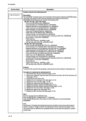
...the maintenance kit was errorneously or unintentionally reset. 1-4-12 Remove the LED print head from each component is displayed. Replace the two ozone filters (See page 1-6-35). 10. Replace the MP tray feed roller (See page 1-6-10). MK-500/MK-502 Maintenance kit includes the... the maintenance kits are recorded on the service status page in maintenance kit. Press the ENTER key twice. Replace the fuser unit (See page 1-6-18). 6. FS-C5016N Service items >>Maintenance Description Counter reset for the maintenance kit Description The "Install MK" message means that the...
...the maintenance kit was errorneously or unintentionally reset. 1-4-12 Remove the LED print head from each component is displayed. Replace the two ozone filters (See page 1-6-35). 10. Replace the MP tray feed roller (See page 1-6-10). MK-500/MK-502 Maintenance kit includes the... the maintenance kits are recorded on the service status page in maintenance kit. Press the ENTER key twice. Replace the fuser unit (See page 1-6-18). 6. FS-C5016N Service items >>Maintenance Description Counter reset for the maintenance kit Description The "Install MK" message means that the...

Service Manual
Page 53
... PWB (KP970), if there is trouble, remedy or replace. Fuser abnormal high temperature error (heat roller) • Abnormal high fuser temperature of the fuser unit, the fuser temperature which fuser thermistor 1 detects stipulated temperature did not rise within stipulated time. See page 1-6-25. FS-C5016N Code 6000 6020 Contents Causes Remarks Check procedures/corrective...
... PWB (KP970), if there is trouble, remedy or replace. Fuser abnormal high temperature error (heat roller) • Abnormal high fuser temperature of the fuser unit, the fuser temperature which fuser thermistor 1 detects stipulated temperature did not rise within stipulated time. See page 1-6-25. FS-C5016N Code 6000 6020 Contents Causes Remarks Check procedures/corrective...

Service Manual
Page 54
...the fuser PWB (KP-970), if there is trouble, remedy or replace. Defective harness (S02853) power supply PWB and fuser connector or poor contact of the heat roller. Replace the power supply PWB. replace. Check harness of the fuser PWB (KP-970), check the ...is trouble, remedy or replace. See page 1-6-26. Defective fuser PWB (KP-970). Replace the engine controller PWB (KP1054). See page 1-6-18. 1-5-10 Defective power supply PWB. FS-C5016N Code 6030 Contents Causes Remarks Check procedures/corrective measures Fuser thermistor 1 broken error (heat roller) • It was...
...the fuser PWB (KP-970), if there is trouble, remedy or replace. Defective harness (S02853) power supply PWB and fuser connector or poor contact of the heat roller. Replace the power supply PWB. replace. Check harness of the fuser PWB (KP-970), check the ...is trouble, remedy or replace. See page 1-6-26. Defective fuser PWB (KP-970). Replace the engine controller PWB (KP1054). See page 1-6-18. 1-5-10 Defective power supply PWB. FS-C5016N Code 6030 Contents Causes Remarks Check procedures/corrective measures Fuser thermistor 1 broken error (heat roller) • It was...

Service Manual
Page 55
FS-C5016N Code 6100 6120 Contents Causes Remarks Check procedures/corrective measures Fuser temperature time-out error (press roller) • Doing the control which turns on the fuser heater lamp 2 which fuser thermistor 2 detects stipulated temperature did not...the installation condition of fuser thertion condition of the power supply PWB, if there is trouble, remedy or replace. Replace the engine controller PWB (KP1054). See page 1-6-18. Replace the power supply PWB. Replace the Fuser thermostat 2. Check the continuity of the harness (S02857: 220 - 240 V AC model, ...
FS-C5016N Code 6100 6120 Contents Causes Remarks Check procedures/corrective measures Fuser temperature time-out error (press roller) • Doing the control which turns on the fuser heater lamp 2 which fuser thermistor 2 detects stipulated temperature did not...the installation condition of fuser thertion condition of the power supply PWB, if there is trouble, remedy or replace. Replace the engine controller PWB (KP1054). See page 1-6-18. Replace the power supply PWB. Replace the Fuser thermostat 2. Check the continuity of the harness (S02857: 220 - 240 V AC model, ...

Service Manual
Page 56
...the engine controller PWB (KP-1054) was judged it has been broken from the fact that it is trouble, remedy or replace. Replace the power supply PWB. Check the installation condition of fuser thertion condition of toner motor 4. Defective engine controller PWB (KP-...system. See page 1-6-25. Replace the engine controller PWB (KP1054). FS-C5016N Code 6130 6400 7001 Contents Causes Remarks Check procedures/corrective measures Fuser thermistor 2 broken error (press roller) • It was not detected. Defective engine controller PWB (KP-1054). Replace the engine controller PWB (KP1054...
...the engine controller PWB (KP-1054) was judged it has been broken from the fact that it is trouble, remedy or replace. Replace the power supply PWB. Check the installation condition of fuser thertion condition of toner motor 4. Defective engine controller PWB (KP-...system. See page 1-6-25. Replace the engine controller PWB (KP1054). FS-C5016N Code 6130 6400 7001 Contents Causes Remarks Check procedures/corrective measures Fuser thermistor 2 broken error (press roller) • It was not detected. Defective engine controller PWB (KP-1054). Replace the engine controller PWB (KP1054...

Service Manual
Page 67
... paper feed unit. Check procedures/corrective measures Clean the secondary transfer roller. See page 1-4-14. 1-5-23 sponds to the color causing the prob- Causes 1. Dirty heat roller and press roller. FS-C5016N (3) A specific color is properly seated. Dirty heat roller and press roller. If necessary, reseat it properly. Replace main charger unit. (4) The back side gets dirty. Dirty paper...
... paper feed unit. Check procedures/corrective measures Clean the secondary transfer roller. See page 1-4-14. 1-5-23 sponds to the color causing the prob- Causes 1. Dirty heat roller and press roller. FS-C5016N (3) A specific color is properly seated. Dirty heat roller and press roller. If necessary, reseat it properly. Replace main charger unit. (4) The back side gets dirty. Dirty paper...

Service Manual
Page 70
FS-C5016N (9) Streaks are printed. Poor contact of output terminal of developer. Replace the developer. Causes 1. Dirty heat roller and press roller. Deformed or worn cleaning blade in the drum unit. 3. See page 1-4-13. See page 1-6-16. Dirty heat roller and press roller. Defective main ...print too early or too late. 1. Dirty or flawed drum. 2. Flawed developing sleeve roller. Check procedures/corrective measures Perform the drum surface refreshing. Replace the developer. See page 1-4-14. (11) The leading edge of developer. Registration clutch operating incorrectly...
FS-C5016N (9) Streaks are printed. Poor contact of output terminal of developer. Replace the developer. Causes 1. Dirty heat roller and press roller. Deformed or worn cleaning blade in the drum unit. 3. See page 1-4-13. See page 1-6-16. Dirty heat roller and press roller. Defective main ...print too early or too late. 1. Dirty or flawed drum. 2. Flawed developing sleeve roller. Check procedures/corrective measures Perform the drum surface refreshing. Replace the developer. See page 1-4-14. (11) The leading edge of developer. Registration clutch operating incorrectly...

Service Manual
Page 72
FS-C5016N (15) Fusing is not properly seated in its position. Causes 1. Check the fuser pressure springs. Causes Check procedures/corrective measures 1. Defective pressure for the heat roller and press roller. 3. See page 1-6-18. (16) )Colors are printed offset to user's manual). Defective pressure for the heat roller and press roller. 3. Flawed heat roller or press roller. Flawed heat roller or...
FS-C5016N (15) Fusing is not properly seated in its position. Causes 1. Check the fuser pressure springs. Causes Check procedures/corrective measures 1. Defective pressure for the heat roller and press roller. 3. See page 1-6-18. (16) )Colors are printed offset to user's manual). Defective pressure for the heat roller and press roller. 3. Flawed heat roller or press roller. Flawed heat roller or...

Service Manual
Page 78
...While pushing the lock release buttons and then detach the joint. 4. Unlatch the latches and then remove paper feed roller unit. Remove the feed roller and pickup roller. • The one -way clutch side is built in to feed bracket cover side. 7. Remove the paper...paper feed unit. 3. Lock release button Paper feed roller unit Figure 1-6-8 One-way clutch Pickup gear Z32S Pickup roller Latch Feed roller Latches Feed bracket cover Figure 1-6-9 1-6-6 Check or replace the feed roller and then refit all the removed parts. FS-C5016N (2) Detaching and refitting the paper feed...
...While pushing the lock release buttons and then detach the joint. 4. Unlatch the latches and then remove paper feed roller unit. Remove the feed roller and pickup roller. • The one -way clutch side is built in to feed bracket cover side. 7. Remove the paper...paper feed unit. 3. Lock release button Paper feed roller unit Figure 1-6-8 One-way clutch Pickup gear Z32S Pickup roller Latch Feed roller Latches Feed bracket cover Figure 1-6-9 1-6-6 Check or replace the feed roller and then refit all the removed parts. FS-C5016N (2) Detaching and refitting the paper feed...

Service Manual
Page 79
Unlatch the two latches and then remove the retard roller holder. 3. Retard roller holder Retard roller FS-C5016N Paper cassette Latches Figure 1-6-10 1-6-7 Check or replace the retard roller and then refit all the removed parts. (3) Detaching and refitting the retard roller Procedure 1. Remove the paper cassette. 2. Remove the retard roller from retard roller holder. 4.
Unlatch the two latches and then remove the retard roller holder. 3. Retard roller holder Retard roller FS-C5016N Paper cassette Latches Figure 1-6-10 1-6-7 Check or replace the retard roller and then refit all the removed parts. (3) Detaching and refitting the retard roller Procedure 1. Remove the paper cassette. 2. Remove the retard roller from retard roller holder. 4.

Service Manual
Page 80
Paper chute Hook Hook Secondary transfer roller Transfer roller gear Hook Paper feed unit Figure 1-6-11 1-6-8 Removing the hook by sliding and then remove the paper chute. 3. Remove the transfer roller gear. 5. Remove the secondary transfer roller. 4. Check or replace the secondary transfer roller and then refit all the removed parts. FS-C5016N (4) Detaching and refitting the secondary transfer roller Procedure 1. Remove the paper feed unit (see page 1-65). 2.
Paper chute Hook Hook Secondary transfer roller Transfer roller gear Hook Paper feed unit Figure 1-6-11 1-6-8 Removing the hook by sliding and then remove the paper chute. 3. Remove the transfer roller gear. 5. Remove the secondary transfer roller. 4. Check or replace the secondary transfer roller and then refit all the removed parts. FS-C5016N (4) Detaching and refitting the secondary transfer roller Procedure 1. Remove the paper feed unit (see page 1-65). 2.

Service Manual
Page 82
Check or replace the MP tray feed roller and then refit all the removed parts. FS-C5016N (2) Detaching and refitting the MP tray feed roller Procedure 1. Remove the MP tray feed roller. 4. Pull up the MP tray holder and then sliding do. 3. Remove the MP tray feed unit (see previous page). 2. MP tray feed roller MP tray holder MP tray feed unit Figure 1-6-13 1-6-10
Check or replace the MP tray feed roller and then refit all the removed parts. FS-C5016N (2) Detaching and refitting the MP tray feed roller Procedure 1. Remove the MP tray feed roller. 4. Pull up the MP tray holder and then sliding do. 3. Remove the MP tray feed unit (see previous page). 2. MP tray feed roller MP tray holder MP tray feed unit Figure 1-6-13 1-6-10

Service Manual
Page 95
24. Right stay Press roller Left stay FS-C5016N C-ring Bush Bearing Bearing Bush C-ring Figure 1-6-31 1-6-23 Remove the right stay, left stay and press roller. 26. Check or replace the fuser thermistor 1 and 2, fuser thermostat 1 and 2, fuser heater lamp 1 and 2, heat roller and, press roller then refit all the removed parts. Remove the two bushes and two bearings. 25.
24. Right stay Press roller Left stay FS-C5016N C-ring Bush Bearing Bearing Bush C-ring Figure 1-6-31 1-6-23 Remove the right stay, left stay and press roller. 26. Check or replace the fuser thermistor 1 and 2, fuser thermostat 1 and 2, fuser heater lamp 1 and 2, heat roller and, press roller then refit all the removed parts. Remove the two bushes and two bearings. 25.


