KM-NET ADMIN Operation Guide for Ver 2.0
Page 100
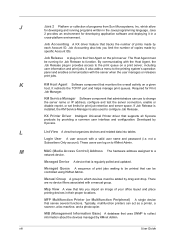
... print server, including user information and print jobs. Job Accounting A KX driver feature that tracks the number of print jobs waiting to function. Typically, multifunction printers can be added by Kyocera. The Host Agent must be controlled using KMnet Admin. Managed Device A ...device that uses SNMP to which allow for print job retention and server space. Map View A view that can act as a printer, a scanner, a fax machine, and a ...
... print server, including user information and print jobs. Job Accounting A KX driver feature that tracks the number of print jobs waiting to function. Typically, multifunction printers can be added by Kyocera. The Host Agent must be controlled using KMnet Admin. Managed Device A ...device that uses SNMP to which allow for print job retention and server space. Map View A view that can act as a printer, a scanner, a fax machine, and a ...
FS-1028MFP/1128MFP Setup Guide Rev-1
Page 34
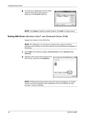
...machine. NOTE: If Windows Security and User Account Control are displayed in the Scanner List field. NOTE: The following is registered to the WIA Driver. NOTE: Click Delete to change names. Setting WIA Driver (Windows Vista™ and Windows® Server 2008) Register this machine ... after installing the driver and software we have specified during installation of WIA Driver. 1 Select Start of the Windows display, Control Panel and then Scanners and Cameras. 2 Select the same name as this machine from WIA Drivers, and press the Properties. Installing Printer Driver 8 The machine ...
...machine. NOTE: If Windows Security and User Account Control are displayed in the Scanner List field. NOTE: The following is registered to the WIA Driver. NOTE: Click Delete to change names. Setting WIA Driver (Windows Vista™ and Windows® Server 2008) Register this machine ... after installing the driver and software we have specified during installation of WIA Driver. 1 Select Start of the Windows display, Control Panel and then Scanners and Cameras. 2 Select the same name as this machine from WIA Drivers, and press the Properties. Installing Printer Driver 8 The machine ...
Service Manual
Page 13
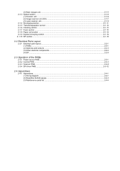
(2) Main charger unit...2-1-5 2-1-3 Optical section ...2-1-6 (1) Scanner unit ...2-1-6 (2) Image scanner unit (ISU) ...2-1-7 (3) Laser scanner unit...2-1-9 2-1-4 Developing section...2-1-11 2-1-5 Transfer/separation section ...2-1-12 2-1-6 Cleaning section ...2-1-13... Other electrical components...2-2-4 (4) DP ...2-2-5 2-3 Operation of the PWBs 2-3-1 Power source PWB...2-3-1 2-3-2 Control PWB ...2-3-3 2-3-3 Scanner PWB ...2-3-9 2-3-4 DP driver PWB...2-3-12 2-4 Appendixes 2-4-1 Appendixes ...2-4-1 (1) Wiring diagram ...2-4-1 (2) Repetitive defects gauge...2-4-3 (3) Maintenance parts list ...2-4-4
(2) Main charger unit...2-1-5 2-1-3 Optical section ...2-1-6 (1) Scanner unit ...2-1-6 (2) Image scanner unit (ISU) ...2-1-7 (3) Laser scanner unit...2-1-9 2-1-4 Developing section...2-1-11 2-1-5 Transfer/separation section ...2-1-12 2-1-6 Cleaning section ...2-1-13... Other electrical components...2-2-4 (4) DP ...2-2-5 2-3 Operation of the PWBs 2-3-1 Power source PWB...2-3-1 2-3-2 Control PWB ...2-3-3 2-3-3 Scanner PWB ...2-3-9 2-3-4 DP driver PWB...2-3-12 2-4 Appendixes 2-4-1 Appendixes ...2-4-1 (1) Wiring diagram ...2-4-1 (2) Repetitive defects gauge...2-4-3 (3) Maintenance parts list ...2-4-4

Service Manual
Page 173
driver from the pits. 3. Hook ISU upper frame Figure 1-5-28 Screw Screw Hooks Figure 1-5-29 1-5-21 (4) Replacing the image scanner unit (ISU) Procedure Removing the image scanner unit (ISU) 1. Remove the connector and then remove the operation panel. 2JN-1 Operation panel Pit Hook Connector Operation panel Pit 4. Unhook three hooks and then remove the ISU upper frame. Remove two screws. 5. Remove the DP (See page 1-5-13). 2. Unhook two hooks by using a flat screw-
driver from the pits. 3. Hook ISU upper frame Figure 1-5-28 Screw Screw Hooks Figure 1-5-29 1-5-21 (4) Replacing the image scanner unit (ISU) Procedure Removing the image scanner unit (ISU) 1. Remove the connector and then remove the operation panel. 2JN-1 Operation panel Pit Hook Connector Operation panel Pit 4. Unhook three hooks and then remove the ISU upper frame. Remove two screws. 5. Remove the DP (See page 1-5-13). 2. Unhook two hooks by using a flat screw-

Service Manual
Page 243
... original sensor DP switchback pressure solenoid DP DP switchback open/close feedshift sensor solenoid Driver Driver Driver DP driver PWB +12V HPSWN LAMP +3.3V1 +24V4 FEEDCLN DPDETN PRESOLN RELSOLN PAGESET OPSWN ORGSWN REVSOLN Motor driver Motor driver LAMP Regulator Power save circuit CPU Scanner PWB +5V1 +3.3V1 Control PWB AFE CSI ASIC Power source +24V1 PWB Figure...
... original sensor DP switchback pressure solenoid DP DP switchback open/close feedshift sensor solenoid Driver Driver Driver DP driver PWB +12V HPSWN LAMP +3.3V1 +24V4 FEEDCLN DPDETN PRESOLN RELSOLN PAGESET OPSWN ORGSWN REVSOLN Motor driver Motor driver LAMP Regulator Power save circuit CPU Scanner PWB +5V1 +3.3V1 Control PWB AFE CSI ASIC Power source +24V1 PWB Figure...

Service Manual
Page 247
... YC108 3 4 3 4 MOT1A MOT1A MOT2B MOT2B +24V4 GND 16 16 15 15 14 14 13 13 12 12 11 11 YC2 DP driver PWB 33 44 9 8 7 9 8 7 TIMSWN GND PI LED (+3.3V1) 13 22 31 6 5 4 6 5 4 ORGSWN GND PI LED (+3.3V1) 3 2 1 3 2 1 OPSWN GND PI LED (+3.3V1) 11 22 ...- 11 22 33 YC101 5 4 5 4 LAMP GND 22 11 (+3.3V3) 3 2 1 3 2 1 PI LED GND HPSWN 33 22 11 Appendixes Home position sensor (1) Wiring diagram Image scanner unit (ISU) LAMP+ feed DP paper Exposure lamp timing original open/close solenoid solenoid sensor sensor sensor pressure feedshift feed clutch DP DP DP 2-4 Appendixes...
... YC108 3 4 3 4 MOT1A MOT1A MOT2B MOT2B +24V4 GND 16 16 15 15 14 14 13 13 12 12 11 11 YC2 DP driver PWB 33 44 9 8 7 9 8 7 TIMSWN GND PI LED (+3.3V1) 13 22 31 6 5 4 6 5 4 ORGSWN GND PI LED (+3.3V1) 3 2 1 3 2 1 OPSWN GND PI LED (+3.3V1) 11 22 ...- 11 22 33 YC101 5 4 5 4 LAMP GND 22 11 (+3.3V3) 3 2 1 3 2 1 PI LED GND HPSWN 33 22 11 Appendixes Home position sensor (1) Wiring diagram Image scanner unit (ISU) LAMP+ feed DP paper Exposure lamp timing original open/close solenoid solenoid sensor sensor sensor pressure feedshift feed clutch DP DP DP 2-4 Appendixes...


