Operation Guide
Page 18
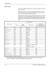
...to eight types of user settings may be selected, but it is also possible for the paper source from the printer's operator panel will cause the printer to automatically select the paper source and print in Cassette mode) Plain Yes Yes Normal 2 Yes Transparency Yes No ...Vellum Yes No Light No Rough Yes Yes Normal 2 Yes Letterhead Yes Yes Normal 2 Yes Color Yes Yes Normal 2 Yes Prepunched Yes Yes Normal 2 Yes Envelope Yes No Heavy 1 (EP C170N/EP No C270N) Heavy 2 (EP C220N) Cardstock Yes No Heavy 2 No Coated Yes No Normal 2 No Thick Yes No Heavy...
...to eight types of user settings may be selected, but it is also possible for the paper source from the printer's operator panel will cause the printer to automatically select the paper source and print in Cassette mode) Plain Yes Yes Normal 2 Yes Transparency Yes No ...Vellum Yes No Light No Rough Yes Yes Normal 2 Yes Letterhead Yes Yes Normal 2 Yes Color Yes Yes Normal 2 Yes Prepunched Yes Yes Normal 2 Yes Envelope Yes No Heavy 1 (EP C170N/EP No C270N) Heavy 2 (EP C220N) Cardstock Yes No Heavy 2 No Coated Yes No Normal 2 No Thick Yes No Heavy...

Operation Guide
Page 31
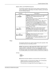
.... (option) No interface is in use . Parallel interface is in use. (EP C270N only) Option serial (RS-232C) interface is in use. (EP C270N only) Network interface is in use . Even after a print job has been completed on page 2-60. • While the printer is currently in use . For details, see Paper Handling on the...
.... (option) No interface is in use . Parallel interface is in use. (EP C270N only) Option serial (RS-232C) interface is in use. (EP C270N only) Network interface is in use . Even after a print job has been completed on page 2-60. • While the printer is currently in use . For details, see Paper Handling on the...
Operation Guide
Page 33
... Waiting. Also, indicates when printing is currently active (shown by switching the printer off -line states. Note that the printer requires maintenance or is switched on page 2-5. NOTE: The printer has a USB, parallel (EP C270N), network, and an optional interface. On. Use this key to a memory card..., hard disk or RAM disk. Data can resolve. Indicates that the printer is being processed before printing starts, or that...
... Waiting. Also, indicates when printing is currently active (shown by switching the printer off -line states. Note that the printer requires maintenance or is switched on page 2-5. NOTE: The printer has a USB, parallel (EP C270N), network, and an optional interface. On. Use this key to a memory card..., hard disk or RAM disk. Data can resolve. Indicates that the printer is being processed before printing starts, or that...
Operation Guide
Page 34
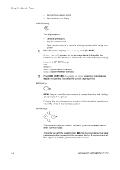
... printing job. • Stop the alarm sound. • Reset numeric values or cancel a setting procedure while using menu system. 1 While the printer displays Processing, press [CANCEL]. CANCEL Key This key is used in the menu system to facilitate jam clearing in use. Print Cancel? A help ... on the message display. Arrow Keys The four arrow keys are used to change the setup and printing environment of the following message: Parallel (EP C270N only) USB Network Serial (option serial interface) Option (option network interface) 2 Press [OK] ([ENTER]). The arrow key with the question...
... printing job. • Stop the alarm sound. • Reset numeric values or cancel a setting procedure while using menu system. 1 While the printer displays Processing, press [CANCEL]. CANCEL Key This key is used in the menu system to facilitate jam clearing in use. Print Cancel? A help ... on the message display. Arrow Keys The four arrow keys are used to change the setup and printing environment of the following message: Parallel (EP C270N only) USB Network Serial (option serial interface) Option (option network interface) 2 Press [OK] ([ENTER]). The arrow key with the question...

Operation Guide
Page 36
The interface is printed. 2-10 ADVANCED OPERATION GUIDE appears on the message display and printing stops after the current page is indicated by the interface in use. Using the Operator Panel Canceling a Printing Job 1 While the printer displays Processing, press [CANCEL]. Cancelling data appears on the message display followed by one of the following messages: Parallel (EP C270N only) USB Network Serial (option serial interface) Option (option network interface) 2 Press [OK] ([ENTER]). Print Cancel?
The interface is printed. 2-10 ADVANCED OPERATION GUIDE appears on the message display and printing stops after the current page is indicated by the interface in use. Using the Operator Panel Canceling a Printing Job 1 While the printer displays Processing, press [CANCEL]. Cancelling data appears on the message display followed by one of the following messages: Parallel (EP C270N only) USB Network Serial (option serial interface) Option (option network interface) 2 Press [OK] ([ENTER]). Print Cancel?
Operation Guide
Page 55
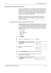
... OPERATION GUIDE 2-29 Normally, this interface is equipped with both parallel (EP C270N) and USB interfaces. A blinking question mark >Parallel I/F (?) appears. ? Using the Operator Panel Changing the Interface Parameters The printer is used under the default setting Auto. NOTE: This interface selection described... bi-directional/high-speed mode according to reset the printer or turn the power off at least once. For details, see Parallel Interface (EP C270N only) on different interfaces by using the printer's menu selection system. Optional serial interface board kit and...
... OPERATION GUIDE 2-29 Normally, this interface is equipped with both parallel (EP C270N) and USB interfaces. A blinking question mark >Parallel I/F (?) appears. ? Using the Operator Panel Changing the Interface Parameters The printer is used under the default setting Auto. NOTE: This interface selection described... bi-directional/high-speed mode according to reset the printer or turn the power off at least once. For details, see Parallel Interface (EP C270N only) on different interfaces by using the printer's menu selection system. Optional serial interface board kit and...

Operation Guide
Page 56
... baud rate, data bits, stop bits, parity, and protocol. A blinking question mark (?) appears. Interface ? Interface ? Serial 5 Press [OK] ([ENTER]) again. 6 Press Z. Changing Serial Interface Parameters (EP C270N only) NOTE: This section applies to the printer having the optional serial interface board kit (IB-11) installed.
... baud rate, data bits, stop bits, parity, and protocol. A blinking question mark (?) appears. Interface ? Interface ? Serial 5 Press [OK] ([ENTER]) again. 6 Press Z. Changing Serial Interface Parameters (EP C270N only) NOTE: This section applies to the printer having the optional serial interface board kit (IB-11) installed.
Operation Guide
Page 120
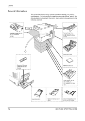
... are explained in the following options available to the documentation included with the option. Envelope Feeder EF-310 (for EP C220N/EP C270N) Printer Face-up Output Tray PT-300 (for EP C170N PT-301 (for EP C220N/EP C270N) Expansion Memory (DIMM 64/128/256/ 512MB) Duplex Unit DU-301 Memory Card (CF) Paper Feeder PF-60...
... are explained in the following options available to the documentation included with the option. Envelope Feeder EF-310 (for EP C220N/EP C270N) Printer Face-up Output Tray PT-300 (for EP C170N PT-301 (for EP C220N/EP C270N) Expansion Memory (DIMM 64/128/256/ 512MB) Duplex Unit DU-301 Memory Card (CF) Paper Feeder PF-60...

Operation Guide
Page 121
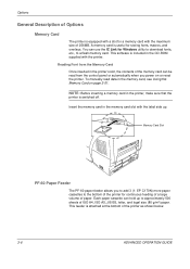
... shown below to 1024MB, remove the 128MB memory module and install two 512MB memory modules. (EP C270N) NOTE: The expansion memory should only be liable for handling the printer's main controller board and memory modules To protect electronic parts, discharge static electricity from 64, ... optional memory modules (dual in line memory modules) in two memory slots provided on the printer main controller board. A 128MB memory module is 1024MB: EP C270N (512MB x 2), 640MB: EP C170N and EP C220N. The maximum memory size is already installed at the factory. Precautions for any damages caused...
... shown below to 1024MB, remove the 128MB memory module and install two 512MB memory modules. (EP C270N) NOTE: The expansion memory should only be liable for handling the printer's main controller board and memory modules To protect electronic parts, discharge static electricity from 64, ... optional memory modules (dual in line memory modules) in two memory slots provided on the printer main controller board. A 128MB memory module is 1024MB: EP C270N (512MB x 2), 640MB: EP C170N and EP C220N. The maximum memory size is already installed at the factory. Precautions for any damages caused...
Operation Guide
Page 124
... storing fonts, macros, and overlays. Reading Font from the control panel or automatically when you to add 3 (1: EP C170N) more paper cassettes to the bottom of the printer for continuous feeding of a large volume of the printer as shown below. 3-6 ADVANCED OPERATION GUIDE This feeder is switched off. NOTE: Before inserting a memory card...
... storing fonts, macros, and overlays. Reading Font from the control panel or automatically when you to add 3 (1: EP C170N) more paper cassettes to the bottom of the printer for continuous feeding of a large volume of the printer as shown below. 3-6 ADVANCED OPERATION GUIDE This feeder is switched off. NOTE: Before inserting a memory card...
Operation Guide
Page 130
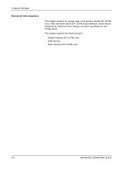
Computer Interface General Information This chapter explains the signals used in the printer's parallel (EP C270N only), USB, and serial (option [EP C270N only]) interfaces. This chapter explains the following topics: • Parallel Interface (EP C270N only) • USB Interface • Serial Interface (EP C270N only) 4-2 ADVANCED OPERATION GUIDE It also lists pin assignments, signal functions, timings, connector specifications, and voltage levels.
Computer Interface General Information This chapter explains the signals used in the printer's parallel (EP C270N only), USB, and serial (option [EP C270N only]) interfaces. This chapter explains the following topics: • Parallel Interface (EP C270N only) • USB Interface • Serial Interface (EP C270N only) 4-2 ADVANCED OPERATION GUIDE It also lists pin assignments, signal functions, timings, connector specifications, and voltage levels.

Operation Guide
Page 131
Computer Interface Parallel Interface (EP C270N only) Communication Modes The printer provides high-speed data transmission on the Data 0 [1] to Data 7 [8] signal lines. In Auto and Nibble modes, these signals are bidirectional. ADVANCED OPERATION GUIDE 4-3 ...Nibble - - Data 7 [8] is also given in Auto mode and Nibble (high) mode (IEEE 1284-compliant). To change communication mode, see Changing Parallel Interface Mode (EP C270N only) on page 2-29. Interface Signals Table shows the connector pins and corresponding input and output signals of data sent from host computer to read...
Computer Interface Parallel Interface (EP C270N only) Communication Modes The printer provides high-speed data transmission on the Data 0 [1] to Data 7 [8] signal lines. In Auto and Nibble modes, these signals are bidirectional. ADVANCED OPERATION GUIDE 4-3 ...Nibble - - Data 7 [8] is also given in Auto mode and Nibble (high) mode (IEEE 1284-compliant). To change communication mode, see Changing Parallel Interface Mode (EP C270N only) on page 2-29. Interface Signals Table shows the connector pins and corresponding input and output signals of data sent from host computer to read...
Operation Guide
Page 134
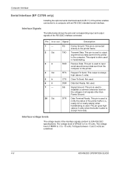
...232C standard serial interface. Not used . Signal Ground. This pin is used to input serial asynchronous data sent from the printer to 15 volts. Interface voltage levels The voltage levels of all signals other than Frame Ground. The pin goes high (... Voltages between -3 and 3 volts are undefined. 4-6 ADVANCED OPERATION GUIDE Request To Send. Not used . Data Terminal Ready. Computer Interface Serial Interface (EP C270N only) Installing the optional serial interface board kit (IB-11) in handshaking. Pin In or out Signal Description 1- 2 Out 3 In 4 Out...
...232C standard serial interface. Not used . Signal Ground. This pin is used to input serial asynchronous data sent from the printer to 15 volts. Interface voltage levels The voltage levels of all signals other than Frame Ground. The pin goes high (... Voltages between -3 and 3 volts are undefined. 4-6 ADVANCED OPERATION GUIDE Request To Send. Not used . Data Terminal Ready. Computer Interface Serial Interface (EP C270N only) Installing the optional serial interface board kit (IB-11) in handshaking. Pin In or out Signal Description 1- 2 Out 3 In 4 Out...

Operation Guide
Page 135
You can verify these parameters on page 2-30. H2: Number of the printer. To change the value for the serial interface parameters, see Changing Serial Interface Parameters (EP C270N only) on the status printout as marked by various devices to send or receive data. This following identifications...nearly-empty threshold • H8: Received data buffer size The parameters can be changed from the printer operator panel. ADVANCED OPERATION GUIDE 4-7 Computer Interface RS-232C Protocol (EP C270N only) Parameters of the RS-232C Protocol A protocol is a set of rules followed by the ...
You can verify these parameters on page 2-30. H2: Number of the printer. To change the value for the serial interface parameters, see Changing Serial Interface Parameters (EP C270N only) on the status printout as marked by various devices to send or receive data. This following identifications...nearly-empty threshold • H8: Received data buffer size The parameters can be changed from the printer operator panel. ADVANCED OPERATION GUIDE 4-7 Computer Interface RS-232C Protocol (EP C270N only) Parameters of the RS-232C Protocol A protocol is a set of rules followed by the ...

Operation Guide
Page 138
... Settings tab and set at the factory as that should be made before power is displayed for DTR. Click on . See Changing Serial Interface Parameters (EP C270N only) on page 2-30. 6 On the computer, set the same parameters as follows: • Baud rate = 9600 bps, data bits (character...other end of the cable into the computer's serial interface connector. 4 Power on Control Panel from the operation panel. The printer executes both computer and printer are set the port properties. 6 After setting the properties, click the OK button. 4-10 ADVANCED OPERATION GUIDE Computer Interface...
... Settings tab and set at the factory as that should be made before power is displayed for DTR. Click on . See Changing Serial Interface Parameters (EP C270N only) on page 2-30. 6 On the computer, set the same parameters as follows: • Baud rate = 9600 bps, data bits (character...other end of the cable into the computer's serial interface connector. 4 Power on Control Panel from the operation panel. The printer executes both computer and printer are set the port properties. 6 After setting the properties, click the OK button. 4-10 ADVANCED OPERATION GUIDE Computer Interface...
Installation Guide
Page 1
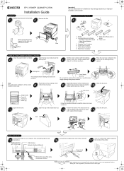
Kyocera Mita assumes no liability for that color. Cyan Toner Container 5. Black Toner Container 7. Close the left sides as shown. Connect the provided power cord to "Setting the Color Registration" procedure on the container until it 5 or 6 times as it clicks ... Ensure the toner container is sold separately.) Parallel Interface (EP C270N only) USB Interface Network Interface (Ethernet) Remove the cap, when using the printer, set the color registration. Apply light pressure to install the other color toner containers. Important! Open the top cover and remove...
Kyocera Mita assumes no liability for that color. Cyan Toner Container 5. Black Toner Container 7. Close the left sides as shown. Connect the provided power cord to "Setting the Color Registration" procedure on the container until it 5 or 6 times as it clicks ... Ensure the toner container is sold separately.) Parallel Interface (EP C270N only) USB Interface Network Interface (Ethernet) Remove the cap, when using the printer, set the color registration. Apply light pressure to install the other color toner containers. Important! Open the top cover and remove...


