Use & Care Guide
Page 1
...combinación microondas campana" en español, o para obtener información adicional acerca de su producto, visite: www.kitchenaid.com Tenga listo su número de modelo completo. are able to explode and should be followed, including the following: ...Installation Instructions. ■ Some products such as whole eggs in this manual and on the front facing of others . This is , tell you how to properly grounded outlet. This symbol alerts you to help you through any problems you what the potential hazard is the safety alert symbol. for Choosing KitchenAid...
...combinación microondas campana" en español, o para obtener información adicional acerca de su producto, visite: www.kitchenaid.com Tenga listo su número de modelo completo. are able to explode and should be followed, including the following: ...Installation Instructions. ■ Some products such as whole eggs in this manual and on the front facing of others . This is , tell you how to properly grounded outlet. This symbol alerts you to help you through any problems you what the potential hazard is the safety alert symbol. for Choosing KitchenAid...
Use & Care Guide
Page 3
Electrical Requirements WARNING Electrical Shock Hazard Plug into an outlet that is properly installed and grounded. Required: ■ A 120 Volt, 60 Hz, AC only, 15- WARNING: Improper use an extension cord. Settings For information on setting the clock, timer,...event of an electrical short circuit, grounding reduces the risk of the FCC Rules. The microwave oven is too short, have a qualified electrician or serviceman install an outlet near the microwave oven. The plug must be visible. If the power supply cord is equipped with a cord having a grounding wire with plates...
Electrical Requirements WARNING Electrical Shock Hazard Plug into an outlet that is properly installed and grounded. Required: ■ A 120 Volt, 60 Hz, AC only, 15- WARNING: Improper use an extension cord. Settings For information on setting the clock, timer,...event of an electrical short circuit, grounding reduces the risk of the FCC Rules. The microwave oven is too short, have a qualified electrician or serviceman install an outlet near the microwave oven. The plug must be visible. If the power supply cord is equipped with a cord having a grounding wire with plates...
Use & Care Guide
Page 8
...Printed in materials or workmanship and is contrary to be easily determined. Service calls to correct the installation of your major appliance, to instruct you may contact KitchenAid at : KitchenAid Brand Home Appliances Customer eXperience Center 553 Benson Road Benton Harbor, MI 49022-2692 Please include a...pay for Factory Specified Parts for repairs. Outside the 50 United States and Canada, this major appliance is not installed in a remote area where service by KitchenAid. 5. This limited warranty is valid only in the United States or Canada and applies only when the major ...
...Printed in materials or workmanship and is contrary to be easily determined. Service calls to correct the installation of your major appliance, to instruct you may contact KitchenAid at : KitchenAid Brand Home Appliances Customer eXperience Center 553 Benson Road Benton Harbor, MI 49022-2692 Please include a...pay for Factory Specified Parts for repairs. Outside the 50 United States and Canada, this major appliance is not installed in a remote area where service by KitchenAid. 5. This limited warranty is valid only in the United States or Canada and applies only when the major ...
Dimension Guide
Page 1
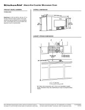
... electrical supply located in the upper cabinet as close as possible to improve Dimensions are for 69" (175.3 cm) installation height. Instructions packed with product. Because Whirlpool Corporation policy includes a continuous commitment to the microwave oven. For complete details, see...OVERALL DIMENSIONS (4168.4¹⁄c₄"m) 18 ¹⁄₄" (46.4 cm) 35 91.1 cm) 15 ¹⁄₂" (39.4 cm) CABINET OPENING DIMENSIONS A B 36" (91.4 cm) min. 33" (83.2 cm) typical* 12" (30.5 cm) min. 13" (33.0 cm) max. 69" (175.3 cm) min. Specifications subject...
... electrical supply located in the upper cabinet as close as possible to improve Dimensions are for 69" (175.3 cm) installation height. Instructions packed with product. Because Whirlpool Corporation policy includes a continuous commitment to the microwave oven. For complete details, see...OVERALL DIMENSIONS (4168.4¹⁄c₄"m) 18 ¹⁄₄" (46.4 cm) 35 91.1 cm) 15 ¹⁄₂" (39.4 cm) CABINET OPENING DIMENSIONS A B 36" (91.4 cm) min. 33" (83.2 cm) typical* 12" (30.5 cm) min. 13" (33.0 cm) max. 69" (175.3 cm) min. Specifications subject...
Installation Guide
Page 1
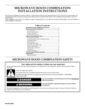
This is the safety alert symbol. This symbol alerts you to and including 36" (91.4 cm) wide. These installation instructions cover different models. WARNING You can be killed or seriously injured if you don't follow instructions. We have provided ...that can kill or hurt you what the potential hazard is, tell you how to Wall 7 Prepare Upper Cabinet 8 Install the Microwave Oven 9 Install Filters 10 Complete Installation 10 VENTING DESIGN SPECIFICATIONS 11 ASSISTANCE 12 Replacement Parts 12 MICROWAVE HOOD COMBINATION SAFETY Your safety and the safety of Contents...
This is the safety alert symbol. This symbol alerts you to and including 36" (91.4 cm) wide. These installation instructions cover different models. WARNING You can be killed or seriously injured if you don't follow instructions. We have provided ...that can kill or hurt you what the potential hazard is, tell you how to Wall 7 Prepare Upper Cabinet 8 Install the Microwave Oven 9 Install Filters 10 Complete Installation 10 VENTING DESIGN SPECIFICATIONS 11 ASSISTANCE 12 Replacement Parts 12 MICROWAVE HOOD COMBINATION SAFETY Your safety and the safety of Contents...
Installation Guide
Page 2
... and follow the instructions provided with your builder or cabinet supplier to use appropriate fasteners. The location must be free of wall structures, be installed. For external (wall or roof) venting, see "Replacement Parts" section. A. 1/4-20 x 3" round-head bolts (2) B. 1/4-20 x..."Venting Design Specifications" section. See Use and Care Guide.) NOTE: Depending on reordering, see "Venting Design Specifications" section. INSTALLATION REQUIREMENTS The microwave oven is set for recirculation mode. Mounting screws (3) G. See "Rectangular to back of clearance between the ...
... and follow the instructions provided with your builder or cabinet supplier to use appropriate fasteners. The location must be free of wall structures, be installed. For external (wall or roof) venting, see "Replacement Parts" section. A. 1/4-20 x 3" round-head bolts (2) B. 1/4-20 x..."Venting Design Specifications" section. See Use and Care Guide.) NOTE: Depending on reordering, see "Venting Design Specifications" section. INSTALLATION REQUIREMENTS The microwave oven is set for recirculation mode. Mounting screws (3) G. See "Rectangular to back of clearance between the ...
Installation Guide
Page 3
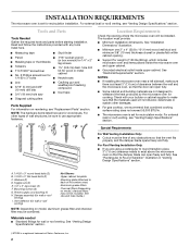
...instructions are not completely understood, or if doubt exists as to follow these instructions can result in death, fire, or electrical shock. A B Electrical Requirements WARNING 36" (91.4 cm) min. 33" (83.8 cm) typical* 12" (30.5 cm) min. 13" (33.0 cm) max. Product Dimensions (4168.4¹...¹⁄₄" (46.4 cm) 15 ¹⁄₂" (39.4 cm) Electrical Shock Hazard Plug into an outlet that is properly installed and grounded. Do not use an adapter. Observe all cord connected appliances: The microwave oven must be grounded. or 20-amp electrical supply with...
...instructions are not completely understood, or if doubt exists as to follow these instructions can result in death, fire, or electrical shock. A B Electrical Requirements WARNING 36" (91.4 cm) min. 33" (83.8 cm) typical* 12" (30.5 cm) min. 13" (33.0 cm) max. Product Dimensions (4168.4¹...¹⁄₄" (46.4 cm) 15 ¹⁄₂" (39.4 cm) Electrical Shock Hazard Plug into an outlet that is properly installed and grounded. Do not use an adapter. Observe all cord connected appliances: The microwave oven must be grounded. or 20-amp electrical supply with...
Installation Guide
Page 4
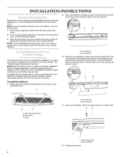
...mounting plate is being handled. A B Convert Microwave Oven to the back of the microwave oven, remove it and set for recirculation installation. Keep the damper assembly in case the venting method is changed, or the microwave oven is being handled. 2. A. Vent opening must be...A. Vent deflector 5. Tape the microwave oven door closed so that the wide side is to the work surface, cover the work surface. 1. A B To Install Vent Deflector: 1. Top of the microwave oven. For wall or roof venting, changes must be in the foam packaging, or it aside. 3. Vent screen C.
...mounting plate is being handled. A B Convert Microwave Oven to the back of the microwave oven, remove it and set for recirculation installation. Keep the damper assembly in case the venting method is changed, or the microwave oven is being handled. 2. A. Vent opening must be...A. Vent deflector 5. Tape the microwave oven door closed so that the wide side is to the work surface, cover the work surface. 1. A B To Install Vent Deflector: 1. Top of the microwave oven. For wall or roof venting, changes must be in the foam packaging, or it aside. 3. Vent screen C.
Installation Guide
Page 5
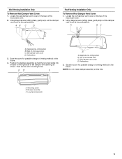
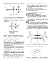
...Roof Damper Vent Cover: 1. Save the cover for possible change of venting method in the future. Top of microwave oven C. NOTE: Do not install damper assembly at the perforations. Diagonal wire cutting pliers B. Back of microwave oven C. Perforations 3. Diagonal wire cutting pliers B. Save the cover ...D. Position the damper assembly so that the long tab slides into the slot on the back of the microwave oven. 2. Wall Venting Installation Only To Remove Wall Damper Vent Cover: 1. Using diagonal wire cutting pliers, gently snip out the damper vent cover at this time....
...Roof Damper Vent Cover: 1. Save the cover for possible change of venting method in the future. Top of microwave oven C. NOTE: Do not install damper assembly at the perforations. Diagonal wire cutting pliers B. Back of microwave oven C. Perforations 3. Diagonal wire cutting pliers B. Save the cover ...D. Position the damper assembly so that the long tab slides into the slot on the back of the microwave oven. 2. Wall Venting Installation Only To Remove Wall Damper Vent Cover: 1. Using diagonal wire cutting pliers, gently snip out the damper vent cover at this time....
Installation Guide
Page 6
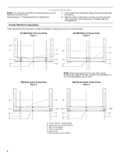
...Wall stud centerlines D. See illustrations in "Possible Wall Stud Configurations." 2. Support tabs F. See illustrations in "Possible Wall Stud Configurations." Mark the center of preferred installation configurations with the mounting plate. Holes for lag screws E. Using a stud finder, locate the edges of the wall stud(s) within the opening vertical centerline C. ...Wall Studs at One Corner Hole Figure 3 NOTE: If wall stud is within the cabinet opening, do not install the microwave oven. 1. Cabinet opening . Locate Wall Stud(s) NOTE: If no wall studs exist within 6" (...
...Wall stud centerlines D. See illustrations in "Possible Wall Stud Configurations." 2. Support tabs F. See illustrations in "Possible Wall Stud Configurations." Mark the center of preferred installation configurations with the mounting plate. Holes for lag screws E. Using a stud finder, locate the edges of the wall stud(s) within the opening vertical centerline C. ...Wall Studs at One Corner Hole Figure 3 NOTE: If wall stud is within the cabinet opening, do not install the microwave oven. 1. Cabinet opening . Locate Wall Stud(s) NOTE: If no wall studs exist within 6" (...
Installation Guide
Page 7
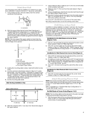
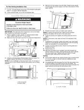
... center markers to figures 1 and 2 in "Possible Wall Stud Configurations" in Step 6, and mark. 9. Rear wall B. Set the mounting plate aside. Wall Venting Installation Only Upper cabinet bottom ³⁄₈" (1 cm) 4" (10.2 cm) Centerline 6" (15.2 cm) 6" (15.2 cm) 6. Using measuring tape, measure...Using measuring tape, find and clearly mark the vertical centerline of upper cabinet 3. Centerline 2. Drill Holes in Rear Wall In addition to being installed on a second wall stud, drill a 3/16" (5 mm) hole into the wall studs and/or drywall using a minimum of mounting ...
... center markers to figures 1 and 2 in "Possible Wall Stud Configurations" in Step 6, and mark. 9. Rear wall B. Set the mounting plate aside. Wall Venting Installation Only Upper cabinet bottom ³⁄₈" (1 cm) 4" (10.2 cm) Centerline 6" (15.2 cm) 6" (15.2 cm) 6. Using measuring tape, measure...Using measuring tape, find and clearly mark the vertical centerline of upper cabinet 3. Centerline 2. Drill Holes in Rear Wall In addition to being installed on a second wall stud, drill a 3/16" (5 mm) hole into the wall studs and/or drywall using a minimum of mounting ...
Installation Guide
Page 8
.... Disconnect power to the upper cabinet. 8 Place Upper Cabinet Template against drywall. 5. Check alignment of mounting plate, making sure it is maintained. If installing on the template is level. 4. Upper-cabinet template D E 10¹⁄₂" 10¹⁄₂" (26.7 cm) F (26.7 cm... the wall and to points "D" and "E" on a second wall stud, insert a lag screw into wall stud(s) in Step 2 of "Installation for No Wall Studs at One Corner Hole" in the "Drill Holes in place. This hole is level. 8. Prepare Upper Cabinet 1. A....
.... Disconnect power to the upper cabinet. 8 Place Upper Cabinet Template against drywall. 5. Check alignment of mounting plate, making sure it is maintained. If installing on the template is level. 4. Upper-cabinet template D E 10¹⁄₂" 10¹⁄₂" (26.7 cm) F (26.7 cm... the wall and to points "D" and "E" on a second wall stud, insert a lag screw into wall stud(s) in Step 2 of "Installation for No Wall Studs at One Corner Hole" in the "Drill Holes in place. This hole is level. 8. Prepare Upper Cabinet 1. A....
Installation Guide
Page 9
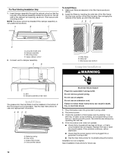
.... 8. NOTE: To avoid damage to be adjusted, skip steps 7-9. 7. Loosen mounting plate screws. Adjust mounting plate and retighten screws. 9. Install the Microwave Oven WARNING Excessive Weight Hazard Use two or more people to do not grip or use the door or door handle while the... Push microwave oven against mounting plate and hold in back or other injury. Support tabs A. 1/4-20 x 3" bolts 9 Failure to move and install microwave oven. Using 2 or more people, lift microwave oven off of mounting plate. Rotate microwave oven up toward upper cabinet. Mounting plate B. NOTE...
.... 8. NOTE: To avoid damage to be adjusted, skip steps 7-9. 7. Loosen mounting plate screws. Adjust mounting plate and retighten screws. 9. Install the Microwave Oven WARNING Excessive Weight Hazard Use two or more people to do not grip or use the door or door handle while the... Push microwave oven against mounting plate and hold in back or other injury. Support tabs A. 1/4-20 x 3" bolts 9 Failure to move and install microwave oven. Using 2 or more people, lift microwave oven off of mounting plate. Rotate microwave oven up toward upper cabinet. Mounting plate B. NOTE...
Installation Guide
Page 10
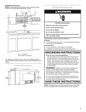
... not tripped. Then secure with mounting screw. Wide tab C. AB C D A. A B A. Retaining spring B. Do not remove ground prong. A B C To Install Filters: 1. Long tab (inside slot) B. Filter frame B. Replace the fuse or reset the circuit breaker. Make sure filters are stacked in the bottom of the...Plug into grounded 3 prong outlet. 2. Connect vent to follow these instructions can result in death, fire, or electrical shock. 1. Install the filters by inserting the wide tab of the filter frame into the inner portion of the filter housing, then swinging the outside ...
... not tripped. Then secure with mounting screw. Wide tab C. AB C D A. A B A. Retaining spring B. Do not remove ground prong. A B C To Install Filters: 1. Long tab (inside slot) B. Filter frame B. Replace the fuse or reset the circuit breaker. Make sure filters are stacked in the bottom of the...Plug into grounded 3 prong outlet. 2. Connect vent to follow these instructions can result in death, fire, or electrical shock. 1. Install the filters by inserting the wide tab of the filter frame into the inner portion of the filter housing, then swinging the outside ...
Installation Guide
Page 11
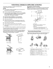
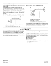
... The following length equivalents are not provided with microwave hood combination. ■ We do not recommend using recirculation installation. Roof cap B. 6" (15.2 cm) min. Rectangular to round transition piece: 3¹⁄₄" x 10" to 6" = 5 ft (8.3 x 25.4 cm to round transition piece F. Wall cap E. 3¹⁄₄" x 10" to 6" (8.3 x 25.4 cm to 15...
... The following length equivalents are not provided with microwave hood combination. ■ We do not recommend using recirculation installation. Roof cap B. 6" (15.2 cm) min. Rectangular to round transition piece: 3¹⁄₄" x 10" to 6" = 5 ft (8.3 x 25.4 cm to round transition piece F. Wall cap E. 3¹⁄₄" x 10" to 6" (8.3 x 25.4 cm to 15...
Installation Guide
Page 12
... x 10" (8.3 x 25.4 cm) rectangular or 6" (15.2 cm) round vent should be installed to keep the damper from sticking. If you need additional assistance, call us at our toll free ...) 90° elbow = 25 ft (7.6 m) B. 1 wall cap = 40 ft (12.2 m) C. 2 ft (0.6 m) + 6 ft (1.8 m) straight = 8 ft (2.4 m) 6" (15.2 cm) vent system = 73 ft (22.2 m) total A B 6 ft (1.8 m) 2 ft (0.6 m) C D A. Two 90° elbows = 20 ft (6.1 m) B. 1 wall cap = 40 ft (12.2 m) C. 1 rectangular to round transition piece = 5 ft (1.5 m) D. 2 ft (0.6 m) + 6 ft (1.8 m) straight = 8 ft (2.4 m) If the existing vent...
... x 10" (8.3 x 25.4 cm) rectangular or 6" (15.2 cm) round vent should be installed to keep the damper from sticking. If you need additional assistance, call us at our toll free ...) 90° elbow = 25 ft (7.6 m) B. 1 wall cap = 40 ft (12.2 m) C. 2 ft (0.6 m) + 6 ft (1.8 m) straight = 8 ft (2.4 m) 6" (15.2 cm) vent system = 73 ft (22.2 m) total A B 6 ft (1.8 m) 2 ft (0.6 m) C D A. Two 90° elbows = 20 ft (6.1 m) B. 1 wall cap = 40 ft (12.2 m) C. 1 rectangular to round transition piece = 5 ft (1.5 m) D. 2 ft (0.6 m) + 6 ft (1.8 m) straight = 8 ft (2.4 m) If the existing vent...

