Use & Care Guide
Page 1
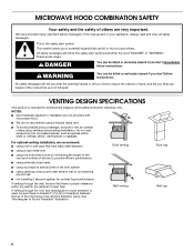
These instructions include a "Troubleshooting" section to potential hazards that you don't immediately follow instructions. For additional information, you can find your complete model and serial number ready. Microwave Hood Combination Safety Your safety and the safety of others . Always read and obey all instructions before using your appliance. Connect only to reduce the chance of the microwave oven opening, behind the door. This is , tell you...
These instructions include a "Troubleshooting" section to potential hazards that you don't immediately follow instructions. For additional information, you can find your complete model and serial number ready. Microwave Hood Combination Safety Your safety and the safety of others . Always read and obey all instructions before using your appliance. Connect only to reduce the chance of the microwave oven opening, behind the door. This is , tell you...
Use & Care Guide
Page 2
... hood or filter. ■ Do not use paper products when appliance is removed from heated surfaces. ■ Do not let cord hang over edge of table or counter. ■ Do not mount over a sink. ■ Do not cover racks or any materials, other part of electric shock. ■ Suitable for use as described in this manual. Do not overcook food. Corrosive cleaning agents, such as lye-based oven...
... hood or filter. ■ Do not use paper products when appliance is removed from heated surfaces. ■ Do not let cord hang over edge of table or counter. ■ Do not mount over a sink. ■ Do not cover racks or any materials, other part of electric shock. ■ Suitable for use as described in this manual. Do not overcook food. Corrosive cleaning agents, such as lye-based oven...
Use & Care Guide
Page 3
... a cord having a grounding wire with a fuse or circuit breaker. The microwave oven is properly grounded. TRUCAPTURE® Ventilation System (on some models) The vent fan comes on automatically during preset or sensor (on some models) The convection element and fan are side by providing an escape wire for manual cooking only. Convection Element and Fan (on if the cooktop below gets too hot. 3 SAVE THESE INSTRUCTIONS This device complies with plates that...
... a cord having a grounding wire with a fuse or circuit breaker. The microwave oven is properly grounded. TRUCAPTURE® Ventilation System (on some models) The vent fan comes on automatically during preset or sensor (on some models) The convection element and fan are side by providing an escape wire for manual cooking only. Convection Element and Fan (on if the cooktop below gets too hot. 3 SAVE THESE INSTRUCTIONS This device complies with plates that...
Use & Care Guide
Page 4
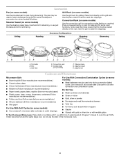
... with gold or silver trim or with 1 cup (250 mL) of cook time at 100%. Use the pan under the rack to catch the drippings. Cookie sheet (not provided) F. If dish becomes hot and the water stays cool, do not use just the base and lid for grilling. Program 1 minute of water beside it. Grill rack D. Use ovenproof, microwave-safe cookware for some models) Use the grill rack for...
... with gold or silver trim or with 1 cup (250 mL) of cook time at 100%. Use the pan under the rack to catch the drippings. Cookie sheet (not provided) F. If dish becomes hot and the water stays cool, do not use just the base and lid for grilling. Program 1 minute of water beside it. Grill rack D. Use ovenproof, microwave-safe cookware for some models) Use the grill rack for...
Use & Care Guide
Page 5
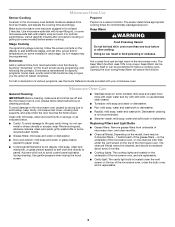
... filter under the bulb cover, and is replaceable. 5 The charcoal filter(s) cannot be cleaned, and should be programmed. Doneness Add or subtract time from food as indicated below. ■ Cavity: To avoid damage to avoid control panel activation during Keep Warm will cancel the function. Clean with your microwave oven. Up to soil buildup, keep cavity, microwave inlet cover, cooking rack supports, and area where the door touches the frame clean. Microwave Oven Use Sensor Cooking A sensor in the microwave oven...
... filter under the bulb cover, and is replaceable. 5 The charcoal filter(s) cannot be cleaned, and should be programmed. Doneness Add or subtract time from food as indicated below. ■ Cavity: To avoid damage to avoid control panel activation during Keep Warm will cancel the function. Clean with your microwave oven. Up to soil buildup, keep cavity, microwave inlet cover, cooking rack supports, and area where the door touches the frame clean. Microwave Oven Use Sensor Cooking A sensor in the microwave oven...
Use & Care Guide
Page 6
... to inside of bread on the tall grill rack, place the rack on the turntable and close the door, then start the cycle. ■ Control Make sure control is on. See "Grill Element" in "Microwave Oven Care" section. Program the microwave oven using these items during convection cooking ■ This is off. Replacement Parts Provided Accessories ■ Turntable ■ Turntable support & rollers ■ Turntable hub ■ Cooking rack (for some models) ■ Rack spacer ■ Rack hook ■ Grease filters ■ Charcoal filter(s) ■ Cooktop light bulb...
... to inside of bread on the tall grill rack, place the rack on the turntable and close the door, then start the cycle. ■ Control Make sure control is on. See "Grill Element" in "Microwave Oven Care" section. Program the microwave oven using these items during convection cooking ■ This is off. Replacement Parts Provided Accessories ■ Turntable ■ Turntable support & rollers ■ Turntable hub ■ Cooking rack (for some models) ■ Rack spacer ■ Rack hook ■ Grease filters ■ Charcoal filter(s) ■ Cooktop light bulb...
Use & Care Guide
Page 8
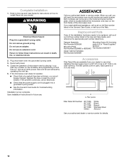
... only in-home service is covered by the customer. Please keep this User Instructions and model number information for other damage to the finish of your major appliance, to replace or repair house fuses, or to correct house wiring or plumbing. 2. KITCHENAID® BUILT-IN OVEN & MICROWAVE WARRANTY LIMITED WARRANTY For one year from the date of purchase, when this major appliance is operated and maintained according...
... only in-home service is covered by the customer. Please keep this User Instructions and model number information for other damage to the finish of your major appliance, to replace or repair house fuses, or to correct house wiring or plumbing. 2. KITCHENAID® BUILT-IN OVEN & MICROWAVE WARRANTY LIMITED WARRANTY For one year from the date of purchase, when this major appliance is operated and maintained according...
Installation Instructions
Page 2
.... Always read and obey all joints in this manual and on your appliance. We have back draft dampers ■ using a rigid metal vent ■ using the most direct route by minimizing the length of the vent and number of elbows to provide efficient performance ■ using uniformly sized vents ■ using duct tape to open fully. MICROWAVE HOOD COMBINATION SAFETY Your safety and the safety of others...
.... Always read and obey all joints in this manual and on your appliance. We have back draft dampers ■ using a rigid metal vent ■ using the most direct route by minimizing the length of the vent and number of elbows to provide efficient performance ■ using uniformly sized vents ■ using duct tape to open fully. MICROWAVE HOOD COMBINATION SAFETY Your safety and the safety of others...

Installation Instructions
Page 3
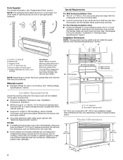
... Tools and Parts Tools Needed Gather the required tools and parts before starting installation. Two 90° elbows = 20 ft (6.1 m) B. 1 wall cap = 40 ft (12.2 m) C. 1 rectangular to round transition piece = 5 ft (1.5 m) D. 2 ft (0.6 m) + 6 ft (1.8 m) straight = 8 ft (2.4 m) If the existing vent is round, a rectangular to keep the damper from sticking. D E F G A. See "Recommended Standard Fittings" section for cabinet 1/4-20 x 3" round-head bolts ■ Keyhole saw ■ Electric drill ■...
... Tools and Parts Tools Needed Gather the required tools and parts before starting installation. Two 90° elbows = 20 ft (6.1 m) B. 1 wall cap = 40 ft (12.2 m) C. 1 rectangular to round transition piece = 5 ft (1.5 m) D. 2 ft (0.6 m) + 6 ft (1.8 m) straight = 8 ft (2.4 m) If the existing vent is round, a rectangular to keep the damper from sticking. D E F G A. See "Recommended Standard Fittings" section for cabinet 1/4-20 x 3" round-head bolts ■ Keyhole saw ■ Electric drill ■...
Installation Instructions
Page 4
... heat produced by the microwave oven for wall or roof venting) Not Shown: Upper cabinet template Mounting plate (attached to make sure there is typical for wall or roof venting. Damper assembly (for cooking. Toggle nuts (4) D. 1/4" x 2" lag screws (4) E. Materials needed ■ Standard fittings for 66" (167.6 cm) installation height. Exact dimensions may vary depending on model, aluminum grease filter and charcoal filter may not be combined. See "Venting Design Specifications" section. See "Electrical Requirements" section. Washers (2) C. See Use...
... heat produced by the microwave oven for wall or roof venting) Not Shown: Upper cabinet template Mounting plate (attached to make sure there is typical for wall or roof venting. Damper assembly (for cooking. Toggle nuts (4) D. 1/4" x 2" lag screws (4) E. Materials needed ■ Standard fittings for 66" (167.6 cm) installation height. Exact dimensions may vary depending on model, aluminum grease filter and charcoal filter may not be combined. See "Venting Design Specifications" section. See "Electrical Requirements" section. Washers (2) C. See Use...
Installation Instructions
Page 5
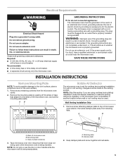
... wire with a fuse or circuit breaker. Do not use the door or door handle while the microwave oven is being handled. Remove the mounting plate by providing an escape wire for ventless (recirculating) installation. A B C Rotate Air Deflector The microwave oven is set for the electric current. Retaining tabs B. Do not remove ground prong. Do not use an extension cord. Electrical Requirements WARNING Electrical Shock Hazard Plug into an outlet that door does not swing open while microwave oven...
... wire with a fuse or circuit breaker. Do not use the door or door handle while the microwave oven is being handled. Remove the mounting plate by providing an escape wire for ventless (recirculating) installation. A B C Rotate Air Deflector The microwave oven is set for the electric current. Retaining tabs B. Do not remove ground prong. Do not use an extension cord. Electrical Requirements WARNING Electrical Shock Hazard Plug into an outlet that door does not swing open while microwave oven...

Installation Instructions
Page 6
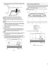
... the microwave oven, and the exhaust port (open end) C. Retaining tabs 6 Rotate air deflector front to back so that deflector feet face the bottom of microwave oven. Microwave oven exhaust port B. Deflector feet C. Save screw for later use. Air deflector exhaust port (open end) C. Repeat Step 1 from "Wall Venting Installation Only." 3. Deflector feet 5. Slide damper plate under the retaining tabs, then secure with microwave oven exhaust port. A A A. Repeat Step 3 from "Wall Venting Installation Only." 4. Microwave oven exhaust port B. Roof Venting Installation Only...
... the microwave oven, and the exhaust port (open end) C. Retaining tabs 6 Rotate air deflector front to back so that deflector feet face the bottom of microwave oven. Microwave oven exhaust port B. Deflector feet C. Save screw for later use. Air deflector exhaust port (open end) C. Repeat Step 1 from "Wall Venting Installation Only." 3. Deflector feet 5. Slide damper plate under the retaining tabs, then secure with microwave oven exhaust port. A A A. Repeat Step 3 from "Wall Venting Installation Only." 4. Microwave oven exhaust port B. Roof Venting Installation Only...
Installation Instructions
Page 7
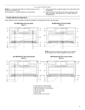
... the cabinet opening, do not install the microwave oven. 1. No Wall Studs at Corner Holes Figure 1 No Wall Studs at All Four Corner Holes Figure 4 A A,E A,E A,E G C G C B E B A A,E A,E A,E F F F F D DD D G G A. Wall vent opening (on mounting plate) B. Support tabs G. Mounting plate center markers 7 Possible Wall Stud Configurations These depictions show examples of preferred installation configurations with the mounting plate. See illustrations in "Possible Wall Stud Configurations." 2. Holes for lag screws F. Locate Wall Stud(s) NOTE: If no wall studs...
... the cabinet opening, do not install the microwave oven. 1. No Wall Studs at Corner Holes Figure 1 No Wall Studs at All Four Corner Holes Figure 4 A A,E A,E A,E G C G C B E B A A,E A,E A,E F F F F D DD D G G A. Wall vent opening (on mounting plate) B. Support tabs G. Mounting plate center markers 7 Possible Wall Stud Configurations These depictions show examples of preferred installation configurations with the mounting plate. See illustrations in "Possible Wall Stud Configurations." 2. Holes for lag screws F. Locate Wall Stud(s) NOTE: If no wall studs...
Installation Instructions
Page 8
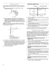
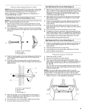
... the centerline(s). Following are ideal hole locations. 5. Installation for Wall Studs at the other 2 corner holes. Using measuring tape, find and clearly mark the vertical centerline of cabinet. D A C B A. Top of mounting plate must align with front edge of the opening. Mark Rear Wall The microwave oven must be installed on a minimum of 1 wall stud, preferably 2, using a minimum of lag screws and 1/4-20 x 3" round-head bolts with...
... the centerline(s). Following are ideal hole locations. 5. Installation for Wall Studs at the other 2 corner holes. Using measuring tape, find and clearly mark the vertical centerline of cabinet. D A C B A. Top of mounting plate must align with front edge of the opening. Mark Rear Wall The microwave oven must be installed on a minimum of 1 wall stud, preferably 2, using a minimum of lag screws and 1/4-20 x 3" round-head bolts with...
Installation Instructions
Page 9
... template has trim lines to go through the drywall, and finger tighten the bolts to make sure toggle nuts have opened against the rear wall so that it is level. 8. Mounting plate C. Position mounting plate on a second wall stud, insert lag screw(s) into the upper cabinet align with the front edge of mounting plate, making sure it is maintained. Securely tighten all 4 corner holes of "Installation...
... template has trim lines to go through the drywall, and finger tighten the bolts to make sure toggle nuts have opened against the rear wall so that it is level. 8. Mounting plate C. Position mounting plate on a second wall stud, insert lag screw(s) into the upper cabinet align with the front edge of mounting plate, making sure it is maintained. Securely tighten all 4 corner holes of "Installation...

Installation Instructions
Page 10
... bottom of mounting plate. Using a keyhole saw, cut out the rectangular area. Push damper assembly through opening C. IMPORTANT: The control side of the shaded rectangular area "F" on Upper Cabinet Template. 8. NOTE: Do not grip or use the door or door handle during installation. Damper assembly D. NOTE: If upper cabinet is the heavy side. Power supply cord bushing 6. Check that tabs in back or other injury. A Install the Microwave Oven WARNING Excessive Weight Hazard Use two...
... bottom of mounting plate. Using a keyhole saw, cut out the rectangular area. Push damper assembly through opening C. IMPORTANT: The control side of the shaded rectangular area "F" on Upper Cabinet Template. 8. NOTE: Do not grip or use the door or door handle during installation. Damper assembly D. NOTE: If upper cabinet is the heavy side. Power supply cord bushing 6. Check that tabs in back or other injury. A Install the Microwave Oven WARNING Excessive Weight Hazard Use two...
Installation Instructions
Page 11
Rotate microwave oven up toward upper cabinet. Loosen mounting plate screws. With the microwave oven centered, and with screw removed in place, insert bolts through the wall, make sure the damper assembly fits easily into microwave oven. Screw D. Damper plate 2. Bolts 11 For Roof Venting Installation Only 1. NOTE: If venting through upper cabinet into the vent tube in the wall cutout. 6. Using 2 or more people, lift microwave oven off of "Rotate Air Deflector." Longer or shorter bolts are available...
Rotate microwave oven up toward upper cabinet. Loosen mounting plate screws. With the microwave oven centered, and with screw removed in place, insert bolts through the wall, make sure the damper assembly fits easily into microwave oven. Screw D. Damper plate 2. Bolts 11 For Roof Venting Installation Only 1. NOTE: If venting through upper cabinet into the vent tube in the wall cutout. 6. Using 2 or more people, lift microwave oven off of "Rotate Air Deflector." Longer or shorter bolts are available...
Installation Instructions
Page 12
... free number listed in a 36" (91.4 cm) or 42" (106.7 cm) wide opening. Save Installation Instructions for future use when installing this microwave oven in the Use and Care Guide, or visit us at 100% power. Both numbers can result in "Parts Supplied" Mounting Plate section) Part Number 8205892 or 8205942 Part Number 8205947 Upper Cabinet Template Part Number 8205926 Accessories Filler Panel Kits are available from your authorized dealer or service center. Damper Assembly Mounting Screw Kit (includes Part Number 8205558 parts A-E in death, fire, or electrical...
... free number listed in a 36" (91.4 cm) or 42" (106.7 cm) wide opening. Save Installation Instructions for future use when installing this microwave oven in the Use and Care Guide, or visit us at 100% power. Both numbers can result in "Parts Supplied" Mounting Plate section) Part Number 8205892 or 8205942 Part Number 8205947 Upper Cabinet Template Part Number 8205926 Accessories Filler Panel Kits are available from your authorized dealer or service center. Damper Assembly Mounting Screw Kit (includes Part Number 8205558 parts A-E in death, fire, or electrical...
Parts Diagram
Page 1
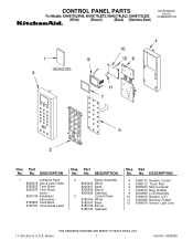
... LCD Assembly 10 8184915 Bracket, LCD 11 8185058 Bushing, Rubber 12 8184919 Sensor, Light Lens 11−05 Litho In U.S.A. (dmm) 1 Part No. 8206290 DESCRIPTION 2 Button Assembly 8205434 White 8205437 Black 8205436 Biscuit 8205092 Stainless 3 Control Panel 8185164 White 8185167 Black 8185166 Biscuit 8185165 Stainless Illus. No. DESCRIPTION 1 Literature Parts 8205975 Use & Care Guide 8205622 Tech Sheet 8205574 Tech Sheet, Insert 8205139 Installation Instructions 8184803 Cook Book 8184723 Cook Guide Label...
... LCD Assembly 10 8184915 Bracket, LCD 11 8185058 Bushing, Rubber 12 8184919 Sensor, Light Lens 11−05 Litho In U.S.A. (dmm) 1 Part No. 8206290 DESCRIPTION 2 Button Assembly 8205434 White 8205437 Black 8205436 Biscuit 8205092 Stainless 3 Control Panel 8185164 White 8185167 Black 8185166 Biscuit 8185165 Stainless Illus. No. DESCRIPTION 1 Literature Parts 8205975 Use & Care Guide 8205622 Tech Sheet 8205574 Tech Sheet, Insert 8205139 Installation Instructions 8184803 Cook Book 8184723 Cook Guide Label...
Parts Diagram
Page 4
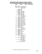
... Right 2 8204670 Lamp 3 4393598 Switch, Micro 4 8184003 Filter, Grease 5 8205381 Plate, Bottom 8204960 (SS Model) 6 8184141 Glass, Lamp 7 8184889 Holder, Glass 8 4393599 Switch, Micro Primary/Secondary 9 8184124 Cover, Inverter 10 4393697 Switch, Micro 11 8169438 Spring, Interlock 12 8205211 Plate, Cam 13 8185189 Support, Interlock 14 8184875 Fan, DC 12 Volt 15 8184894 Housing, Fan 16 8204989 Inverter 40 W 17 8185032 Bracket, Holder 18 8184670 Holder, Inverter 19 8185190 Rod−Locking Link 20...
... Right 2 8204670 Lamp 3 4393598 Switch, Micro 4 8184003 Filter, Grease 5 8205381 Plate, Bottom 8204960 (SS Model) 6 8184141 Glass, Lamp 7 8184889 Holder, Glass 8 4393599 Switch, Micro Primary/Secondary 9 8184124 Cover, Inverter 10 4393697 Switch, Micro 11 8169438 Spring, Interlock 12 8205211 Plate, Cam 13 8185189 Support, Interlock 14 8184875 Fan, DC 12 Volt 15 8184894 Housing, Fan 16 8204989 Inverter 40 W 17 8185032 Bracket, Holder 18 8184670 Holder, Inverter 19 8185190 Rod−Locking Link 20...


