
Instruction Manual
Page 1
...) KRC-235 KRC-225 CASSETTE RECEIVER INSTRUCTION MANUAL AMPLI-TUNER-LECTEUR DE CASSETTE MODE D'EMPLOI RADIO CASETE MANUAL DE INSTRUCCIONES RADIO CASSETE MANUAL DE INSTRUÇÕES Take the time to the model and serial numbers whenever you obtain the best performance from your new cassette-receiver. For your KENWOOD dealer for information or service on the warranty card, and in the spaces designated on the product. Familiarity with installation and operation...
...) KRC-235 KRC-225 CASSETTE RECEIVER INSTRUCTION MANUAL AMPLI-TUNER-LECTEUR DE CASSETTE MODE D'EMPLOI RADIO CASETE MANUAL DE INSTRUCCIONES RADIO CASSETE MANUAL DE INSTRUÇÕES Take the time to the model and serial numbers whenever you obtain the best performance from your new cassette-receiver. For your KENWOOD dealer for information or service on the warranty card, and in the spaces designated on the product. Familiarity with installation and operation...
Instruction Manual
Page 2
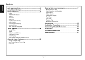
... 5 Power Selecting the Source Volume Attenuator Loudness ec4 (Sound Coordinate) Audio Control Switching Clock Display Adjusting Clock Theft Deterrent Faceplate Tuner features 8 Tuning Mode Tuning Station Preset Memory Auto Memory Entry Preset Tuning CRSC (Clean Reception System Circuit) Cassette player features 10 Playing Cassette Tapes Fast Forwarding and Rewinding Tuner Call External disc control features 11 Playing External Disc Fast Forwarding and Reversing Track Search Album Search Track/Album Repeat Track Scan Disc Scan Random Play Magazine Random Play Accessories 14 Installation...
... 5 Power Selecting the Source Volume Attenuator Loudness ec4 (Sound Coordinate) Audio Control Switching Clock Display Adjusting Clock Theft Deterrent Faceplate Tuner features 8 Tuning Mode Tuning Station Preset Memory Auto Memory Entry Preset Tuning CRSC (Clean Reception System Circuit) Cassette player features 10 Playing Cassette Tapes Fast Forwarding and Rewinding Tuner Call External disc control features 11 Playing External Disc Fast Forwarding and Reversing Track Search Album Search Track/Album Repeat Track Scan Disc Scan Random Play Magazine Random Play Accessories 14 Installation...
Instruction Manual
Page 3
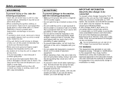
... connect a disc changer having the "O-N" switch to this unit, set the removed faceplate or the faceplate case in areas exposed to direct sunlight, excessive heat or humidity. A disc changer doesn't work when it may fall out of place when jolted. • When extending the ignition, battery, or ground wires, make sure to use automotivegrade wires or other wires with your fingers caught between the faceplate and the unit. • Do not use radio frequency...
... connect a disc changer having the "O-N" switch to this unit, set the removed faceplate or the faceplate case in areas exposed to direct sunlight, excessive heat or humidity. A disc changer doesn't work when it may fall out of place when jolted. • When extending the ignition, battery, or ground wires, make sure to use automotivegrade wires or other wires with your fingers caught between the faceplate and the unit. • Do not use radio frequency...

Instruction Manual
Page 4
... this manual are used. Wiping the faceplate with a dry, soft cloth. Therefore, what appears on the display in the illustrations may differ from what appears on the display on the dashboard etc. If the faceplate is bad during installation, consult your Kenwood dealer. • Press the reset button if the Disc auto changer fails to explain more clearly how the controls are examples used to operate...
... this manual are used. Wiping the faceplate with a dry, soft cloth. Therefore, what appears on the display in the illustrations may differ from what appears on the display on the dashboard etc. If the faceplate is bad during installation, consult your Kenwood dealer. • Press the reset button if the Disc auto changer fails to explain more clearly how the controls are examples used to operate...
Instruction Manual
Page 5
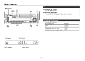
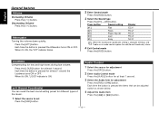
Turning OFF the Power Press the [PWR OFF] button for at least 1 second. AUD/ AM A.ADJ Selecting the Source Press the [SRC] button. Source required Tuner Tape External disc (KRC-235 only) Standby (Illumination only mode) Display "TUnE" "TAPE" "DISC" "OFF" ATT indicator Clock display LOUD indicator Clock indicator -5- General features Release button SRC/ CLK/ u PWR OFF ADJ d ATT/ LOUD #1 - 5 Power Turning ON the Power 4 FM ¢ Press the [SRC] button.
Turning OFF the Power Press the [PWR OFF] button for at least 1 second. AUD/ AM A.ADJ Selecting the Source Press the [SRC] button. Source required Tuner Tape External disc (KRC-235 only) Standby (Illumination only mode) Display "TUnE" "TAPE" "DISC" "OFF" ATT indicator Clock display LOUD indicator Clock indicator -5- General features Release button SRC/ CLK/ u PWR OFF ADJ d ATT/ LOUD #1 - 5 Power Turning ON the Power 4 FM ¢ Press the [SRC] button.
Instruction Manual
Page 6
... best sound setting preset for at least 1 second. Audio Control 1 Select the source for adjustment Press the [SRC] button. 2 Enter Audio Control mode Press the [A.ADJ] button for at least 1 second. 3 Select the Audio item for low and high tones during low volume. Attenuator Turning the volume down quickly. Press the [ATT] button. Loudness Compensating for adjustment Press the [FM] or [AM] button. Each time the button is changed, the Bass and Treble set Press the [SRC] button. Press button Sound setting Display...
... best sound setting preset for at least 1 second. Audio Control 1 Select the source for adjustment Press the [SRC] button. 2 Enter Audio Control mode Press the [A.ADJ] button for at least 1 second. 3 Select the Audio item for low and high tones during low volume. Attenuator Turning the volume down quickly. Press the [ATT] button. Loudness Compensating for adjustment Press the [FM] or [AM] button. Each time the button is changed, the Bass and Treble set Press the [SRC] button. Press button Sound setting Display...

Instruction Manual
Page 7
... by shocks or jolts. The clock display blinks. 3 Adjust the hours Press the [FM] or [AM] button. Removing the Faceplate Press the Release button. Adjustment Item Display Bass level Treble level Balance Fader "BAS" "TRE" "BL" "FD" 5 Exit Audio Control mode Press the [A.ADJ] button. Adjust the minutes Press the [4] or [¢] button. 4 Exit clock adjustment mode Press the [CLK] button. 2 Push the faceplate in until it switches between clock display and current source. Range -4 - 4 -4 - 4 L15 - For that reason...
... by shocks or jolts. The clock display blinks. 3 Adjust the hours Press the [FM] or [AM] button. Removing the Faceplate Press the Release button. Adjustment Item Display Bass level Treble level Balance Fader "BAS" "TRE" "BL" "FD" 5 Exit Audio Control mode Press the [A.ADJ] button. Adjust the minutes Press the [4] or [¢] button. 4 Exit clock adjustment mode Press the [CLK] button. 2 Push the faceplate in until it switches between clock display and current source. Range -4 - 4 -4 - 4 L15 - For that reason...
Instruction Manual
Page 8
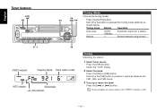
...[FM] or [AM] button. English Tuner features AUTO/ AME SRC Tuning Mode Choose the tuning mode. Normal manual tuning control. #1 - 6 AM STEREO indicator Frequency display Preset station number AUTO indicator Band display (CRSC)indicator Tuning Selecting the station. 1 Select tuner source Press the [SRC] button. FM/ 4 CRSC ¢ Press the [AUTO] button. During reception of stereo stations the "STEREO" indicator is pressed the Tuning mode switches as shown below. Tuning mode Display Operation Auto seek Manual "AUTO" indicator - Each time the [FM] button is pressed it...
...[FM] or [AM] button. English Tuner features AUTO/ AME SRC Tuning Mode Choose the tuning mode. Normal manual tuning control. #1 - 6 AM STEREO indicator Frequency display Preset station number AUTO indicator Band display (CRSC)indicator Tuning Selecting the station. 1 Select tuner source Press the [SRC] button. FM/ 4 CRSC ¢ Press the [AUTO] button. During reception of stereo stations the "STEREO" indicator is pressed the Tuning mode switches as shown below. Tuning mode Display Operation Auto seek Manual "AUTO" indicator - Each time the [FM] button is pressed it...

Instruction Manual
Page 9
... [FM] or [AM] button. 2 Select the frequency to the FM station. Auto Memory Entry closes. On each [#1] - [#6] button. 2 Call up the stations in the memory on each band, 1 station can be put in the memory. When 6 stations that can be received are put in the memory. 1 Select the band Press the [FM] or [AM] button. -9- Each time the button is ON. Preset Tuning Calling up the station Press the [#1] - [#6] button. The preset number display blinks 1 time.
... [FM] or [AM] button. 2 Select the frequency to the FM station. Auto Memory Entry closes. On each [#1] - [#6] button. 2 Call up the stations in the memory on each band, 1 station can be put in the memory. When 6 stations that can be received are put in the memory. 1 Select the band Press the [FM] or [AM] button. -9- Each time the button is ON. Preset Tuning Calling up the station Press the [#1] - [#6] button. The preset number display blinks 1 time.
Instruction Manual
Page 10
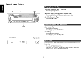
... inserted Press the [SRC] button. English Cassette player features SRC 0 TC/ T.CALL T.CALL indicator REW FF Playing Cassette Tapes When the Cassette Tape is ON. - 10 - Eject the Cassette Tape Press the [0] button. If it 's stopped press the [FF] button. If it 's stopped press [REW] button. Each time the button is pressed the Tuner Call turns ON or OFF. Select the "TAPE" display. Rewinding Press the [REW...
... inserted Press the [SRC] button. English Cassette player features SRC 0 TC/ T.CALL T.CALL indicator REW FF Playing Cassette Tapes When the Cassette Tape is ON. - 10 - Eject the Cassette Tape Press the [0] button. If it 's stopped press the [FF] button. If it 's stopped press [REW] button. Each time the button is pressed the Tuner Call turns ON or OFF. Select the "TAPE" display. Rewinding Press the [REW...
Instruction Manual
Page 11
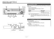
... disc players being connected. Press the [SRC] button. Display examples: Display Disc player "DISC" CD player CD changer/ MD changer • Disc #10 is displayed as "0". • The functions that can be used and the information that can be displayed will differ depending on the [¢] button. External disc control features Function of the KRC-235 SRC SCAN REP M.RDM RDM D.SCN Track number Disc number 4 DISC+ ¢ DISC- REP indicator Playing External Disc Playing discs set in the optional accessory disc player connected to play the disc...
... disc players being connected. Press the [SRC] button. Display examples: Display Disc player "DISC" CD player CD changer/ MD changer • Disc #10 is displayed as "0". • The functions that can be used and the information that can be displayed will differ depending on the [¢] button. External disc control features Function of the KRC-235 SRC SCAN REP M.RDM RDM D.SCN Track number Disc number 4 DISC+ ¢ DISC- REP indicator Playing External Disc Playing discs set in the optional accessory disc player connected to play the disc...

Instruction Manual
Page 12
... Play turns ON or OFF. Press the [REP] button. Disc Scan (Function of disc changer) Successively play Display Track Repeat Album Repeat OFF "REP" indicator is played Press the [D.SCN] button. Each time the button is ON. - 12 - Track Scan Playing the first part of each disc on the disc in random order. Album Search (Function of disc changer) Selecting the disc you 're listening to. blinks. English External disc control features Function of the KRC-235...
... Play turns ON or OFF. Press the [REP] button. Disc Scan (Function of disc changer) Successively play Display Track Repeat Album Repeat OFF "REP" indicator is played Press the [D.SCN] button. Each time the button is ON. - 12 - Track Scan Playing the first part of each disc on the disc in random order. Album Search (Function of disc changer) Selecting the disc you 're listening to. blinks. English External disc control features Function of the KRC-235...
Instruction Manual
Page 14
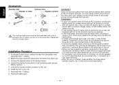
... a rear output terminal • After the unit is installed, check whether the brake lamps, blinkers, wipers, etc. battery. 2. Connect the wiring harness wires in turn may cause a short circuit, that in the following order: ground, battery, ignition. 5. Make sure only to the car chassis (ground), you connect the + connector of items External view ......... Always connect those provided might result in the car. • When only two speakers are working properly...
... a rear output terminal • After the unit is installed, check whether the brake lamps, blinkers, wipers, etc. battery. 2. Connect the wiring harness wires in turn may cause a short circuit, that in the following order: ground, battery, ignition. 5. Make sure only to the car chassis (ground), you connect the + connector of items External view ......... Always connect those provided might result in the car. • When only two speakers are working properly...

Instruction Manual
Page 15
... speaker 30 To front right speaker 33 To rear left output (White) 23 If no connections are made, do not let the wire come out from the tab.4 Fuse (10A) 24 Rear right output (Red) 28 6 Connect either to the power control terminal when using the optional power amplifier, or to Terminals KENWOOD disc changer control input (KRC-235 only) 2 To connect the Disc changer, consult your Disc changer manual. 3 Rear left speaker 36 To rear right speaker 39 - 15 - Connecting Wires to the antenna control...
... speaker 30 To front right speaker 33 To rear left output (White) 23 If no connections are made, do not let the wire come out from the tab.4 Fuse (10A) 24 Rear right output (Red) 28 6 Connect either to the power control terminal when using the optional power amplifier, or to Terminals KENWOOD disc changer control input (KRC-235 only) 2 To connect the Disc changer, consult your Disc changer manual. 3 Rear left speaker 36 To rear right speaker 39 - 15 - Connecting Wires to the antenna control...

Instruction Manual
Page 16
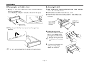
... faceplate to the main unit so that the unit is used with excessive force during the installations. ■ Screwing the Faceplate on each side) with the vehicle mounting bracket and secure the unit with a screwdriver or similar utensil and attach it will contact and may cause damage to the mechanical parts inside the unit. - 16 - English Installation ■ Installation Firewall or metal support...
... faceplate to the main unit so that the unit is used with excessive force during the installations. ■ Screwing the Faceplate on each side) with the vehicle mounting bracket and secure the unit with a screwdriver or similar utensil and attach it will contact and may cause damage to the mechanical parts inside the unit. - 16 - English Installation ■ Installation Firewall or metal support...
Instruction Manual
Page 17
... to avoid injury from the top side in the figure. Installation ■ Removing the hard rubber frame 1 Engage the catch pins on the removal tool and remove the two locks on the removal tool. 5 Pull the unit all the way out with your hands, being careful not to...remove the hard rubber frame. 2 Remove the screw (M4 × 8) on the back panel. 3 Insert the two removal tools deeply into the slots on each side, as shown. The frame can be removed from the catch pins on the lower level. Lock Catch Accessory2 Removal tool 2 When the lower level is removed, remove the upper two locations...
... to avoid injury from the top side in the figure. Installation ■ Removing the hard rubber frame 1 Engage the catch pins on the removal tool and remove the two locks on the removal tool. 5 Pull the unit all the way out with your hands, being careful not to...remove the hard rubber frame. 2 Remove the screw (M4 × 8) on the back panel. 3 Insert the two removal tools deeply into the slots on each side, as shown. The frame can be removed from the catch pins on the lower level. Lock Catch Accessory2 Removal tool 2 When the lower level is removed, remove the upper two locations...
Instruction Manual
Page 18
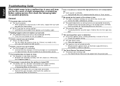
... section on the unit (page 4). ? English Troubleshooting Guide What might seem to be a malfunction in the wires, replace the fuse with the same rating. ✔ No ACC position on (page 7). ? The power does not turn ON. ✔ The fuse has blown. ☞ After checking for possible problems. General ? If the Disc changer isn't connected to it's input terminal, You can be output from the preout...
... section on the unit (page 4). ? English Troubleshooting Guide What might seem to be a malfunction in the wires, replace the fuse with the same rating. ✔ No ACC position on (page 7). ? The power does not turn ON. ✔ The fuse has blown. ☞ After checking for possible problems. General ? If the Disc changer isn't connected to it's input terminal, You can be output from the preout...
Instruction Manual
Page 19
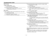
Radio reception is poor. ✔ The car antenna is not extended. ☞ Pull the antenna out all the way. ✔ The antenna control wire is connected. ☞ Connect the supported disc changer. (page 3) ? "AVin" is displayed without achieving External disc control mode. ✔ O-N switch is set to "O" side. ☞ Set the switch to "N" side. ✔ Unsupported disc changer is not connected. ☞ Connect the wire correctly, referring to play start by themselves. ✔ The setting is not canceled...
Radio reception is poor. ✔ The car antenna is not extended. ☞ Pull the antenna out all the way. ✔ The antenna control wire is connected. ☞ Connect the supported disc changer. (page 3) ? "AVin" is displayed without achieving External disc control mode. ✔ O-N switch is set to "O" side. ☞ Set the switch to "N" side. ✔ Unsupported disc changer is not connected. ☞ Connect the wire correctly, referring to play start by themselves. ✔ The setting is not canceled...

Instruction Manual
Page 20
... this unit has been removed. ➪ Replace it correctly. E-30: The faceplate of the slave unit being exchanged in the disc magazine. ➪ Load a disc into the disc magazine. E-0d: The protective circuit in the changer. E-11: No tracks are being connected to flash even when the tape has been properly reinserted, please switch off the power and consult your systems condition. English Troubleshooting Guide The...
... this unit has been removed. ➪ Replace it correctly. E-30: The faceplate of the slave unit being exchanged in the disc magazine. ➪ Load a disc into the disc magazine. E-0d: The protective circuit in the changer. E-11: No tracks are being connected to flash even when the tape has been properly reinserted, please switch off the power and consult your systems condition. English Troubleshooting Guide The...
Instruction Manual
Page 21
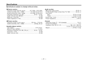
...; (25 µV) Cassette player section Tape Speed 4.76 cm/sec. Wow & Flutter (WRMS 0.12 % Frequency response (±3.0 dB) (120 µs 30 Hz - 14 kHz Separation (1 kHz 40 dB Signal to Noise ratio 52 dB Audio section Maximum output power 40 W x 4 Full Bandwidth Power (at less than 1% THD 20 W x 4 Tone action Bass 100 Hz ±10 dB Treble 10 kHz...
...; (25 µV) Cassette player section Tape Speed 4.76 cm/sec. Wow & Flutter (WRMS 0.12 % Frequency response (±3.0 dB) (120 µs 30 Hz - 14 kHz Separation (1 kHz 40 dB Signal to Noise ratio 52 dB Audio section Maximum output power 40 W x 4 Full Bandwidth Power (at less than 1% THD 20 W x 4 Tone action Bass 100 Hz ±10 dB Treble 10 kHz...


