Use and Care Guide
Page 2
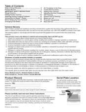
.... 7. A service technician to one year from the date of purchase, call 27=28 Protection Agreements 29 Sears Service 30 Kenmore Warranty When installed, operated and maintained according to all instructions supplied with the product, if this appliance fails due to ...improper operation or maintenance. 3. This warranty covers only defects in material and workmanship. Table of Contents Slide=in Range Warranty 2 Product Record 2 IMPORTANT SAFETY INSTRUCTIONS 3=5 Range Features 6 Setting Surface Controls 7=9 Selecting Surface Cooking Cookware 10 Setting Warm & Ready TM Drawer 11...
.... 7. A service technician to one year from the date of purchase, call 27=28 Protection Agreements 29 Sears Service 30 Kenmore Warranty When installed, operated and maintained according to all instructions supplied with the product, if this appliance fails due to ...improper operation or maintenance. 3. This warranty covers only defects in material and workmanship. Table of Contents Slide=in Range Warranty 2 Product Record 2 IMPORTANT SAFETY INSTRUCTIONS 3=5 Range Features 6 Setting Surface Controls 7=9 Selecting Surface Cooking Cookware 10 Setting Warm & Ready TM Drawer 11...

Use and Care Guide
Page 13
... cakes, pies, biscuits & muffins 1 rack Multiple racks 2 or 3 2 &4 Frozen pies, angel food cake, yeast, bread, casseroles, small cuts of the rack upward and slide the rack back into place. It may also stop immediately and then turn "ON" after a while. This venting is open. Before Setting Oven Controls This... range has a fan that will turn "ON" and "OFF" by itself to run after the range has been turned "OFF", but may continue to keep the electronics cool. Removing and Replacing Oven ...
... cakes, pies, biscuits & muffins 1 rack Multiple racks 2 or 3 2 &4 Frozen pies, angel food cake, yeast, bread, casseroles, small cuts of the rack upward and slide the rack back into place. It may also stop immediately and then turn "ON" after a while. This venting is open. Before Setting Oven Controls This... range has a fan that will turn "ON" and "OFF" by itself to run after the range has been turned "OFF", but may continue to keep the electronics cool. Removing and Replacing Oven ...
Use and Care Guide
Page 27
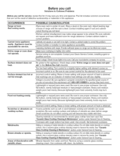
... Cleaning & Maintenance" section under General Care & Cleaning. Sliding or scraping of utensils are not sure about this requirement call for service, review this Before You Call checklist. Contact your local electric company for service. Call your Sears Service Center, installing agent..., dry bottoms. iiiiiii_il;_;!i ...ii.i...... 27 Lightweight or warped pans were used . Sliding or scraping of defective workmanship or materials in center of heat is obtained. OCCURRENCE Range not level. Use a ceramic-glass cooktop cleaning cream to correct problem, Cabinets not...
... Cleaning & Maintenance" section under General Care & Cleaning. Sliding or scraping of utensils are not sure about this requirement call for service, review this Before You Call checklist. Contact your local electric company for service. Call your Sears Service Center, installing agent..., dry bottoms. iiiiiii_il;_;!i ...ii.i...... 27 Lightweight or warped pans were used . Sliding or scraping of defective workmanship or materials in center of heat is obtained. OCCURRENCE Range not level. Use a ceramic-glass cooktop cleaning cream to correct problem, Cabinets not...
Installation Instructions
Page 3
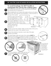
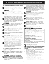
... After the installation, MAKE SUREthat the uni is supported by the leveling legs NOT by the cooktop. .-Tosuccessfully install range, the initial level height from the floor to underside of cooktop glass frame should be at least 1/16" (see ...(see hatched area on each side of the counter. Level the unit if needed. Illustration 2 3 Level the range using the four (4)leveling legs so that the height from the floor to Clear Space for proper unit support. ... leveled (see illustration 2) or could cause glass breakage voiding the warranty. Illustration 1 Slide the unit into the cabinet.
... After the installation, MAKE SUREthat the uni is supported by the leveling legs NOT by the cooktop. .-Tosuccessfully install range, the initial level height from the floor to underside of cooktop glass frame should be at least 1/16" (see ...(see hatched area on each side of the counter. Level the unit if needed. Illustration 2 3 Level the range using the four (4)leveling legs so that the height from the floor to Clear Space for proper unit support. ... leveled (see illustration 2) or could cause glass breakage voiding the warranty. Illustration 1 Slide the unit into the cabinet.

Installation Instructions
Page 5
...rear wire cover (access cover) upward to Terminal Block & Grounding Strap Electrical Shock Hazard o Electrical ground is shipped from the frame and cut the other wires to terminal block while connecting range. remove the grounding strap from factory with the frame grounded by means of... supply cord (see Figure 2). 2. NOTE: Electric Slide-in Range is required on figure 4. Access to expose range terminal connection block (see Figure 3): 1. Match wires and terminals by means of fire or electrical shock exists if an incorrect size range cord kit is used in USA, in usual...
...rear wire cover (access cover) upward to Terminal Block & Grounding Strap Electrical Shock Hazard o Electrical ground is shipped from the frame and cut the other wires to terminal block while connecting range. remove the grounding strap from factory with the frame grounded by means of... supply cord (see Figure 2). 2. NOTE: Electric Slide-in Range is required on figure 4. Access to expose range terminal connection block (see Figure 3): 1. Match wires and terminals by means of fire or electrical shock exists if an incorrect size range cord kit is used in USA, in usual...
Installation Instructions
Page 8
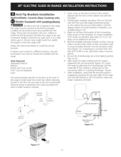
... (lie on the same plane) around the 3 sides that are adjacent to Leveling the range: Models equipped with Leveling Device". Slide the range into the cutout opening . 1. Level the range (see section 6). Models Equipped with Leveling Device") the back leveling leg until the cooktop ... or gaps between the countertop and the range cooktop may occur. Follow the instructions under "Leveling the Range-Models Equipped with care. Follow the instructions under "Leveling the Range- Slide the range into the cutout opening . Open the range drawer. install the anti-tip bracket at...
... (lie on the same plane) around the 3 sides that are adjacent to Leveling the range: Models equipped with Leveling Device". Slide the range into the cutout opening . 1. Level the range (see section 6). Models Equipped with Leveling Device") the back leveling leg until the cooktop ... or gaps between the countertop and the range cooktop may occur. Follow the instructions under "Leveling the Range-Models Equipped with care. Follow the instructions under "Leveling the Range- Slide the range into the cutout opening . Open the range drawer. install the anti-tip bracket at...
Installation Instructions
Page 9
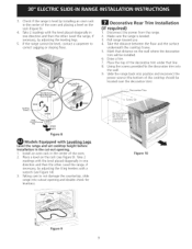
...underneath the cooktop frame. , Mark that line. 8. Using the screws provided fix the decorative trim into the wall. , Slide the range back into cutout opening . 1. Place a level on the wall where the decorative trim will be located over the decorative ...rangecannotbelevel,contacta carpentetro correcst aggingor slopingfloor. | Decorative Rear Trim Installation (if required) 1. Make sure the range is leveled. 3. Taking care to not damage the countertop, slide range into position and reconnect the power source (the bottom of the oven. 2. Checkif therangeis levebl y ...
...underneath the cooktop frame. , Mark that line. 8. Using the screws provided fix the decorative trim into the wall. , Slide the range back into cutout opening . 1. Place a level on the wall where the decorative trim will be located over the decorative ...rangecannotbelevel,contacta carpentetro correcst aggingor slopingfloor. | Decorative Rear Trim Installation (if required) 1. Make sure the range is leveled. 3. Taking care to not damage the countertop, slide range into position and reconnect the power source (the bottom of the oven. 2. Checkif therangeis levebl y ...
Installation Instructions
Page 11
...of the cutout) aligned with the range. Slide range into the floor. 4. The screws provided will allow the range to solid floor (Figure 12). pilot holes using a masonry drill bit. 5. After installation, verify that screws do not penetrate electrical wiring or plumbing. Unfold paper template ...and place it forward to make sure range is ever moved to a different location, the antitip brackets must also be secured to tip...
...of the cutout) aligned with the range. Slide range into the floor. 4. The screws provided will allow the range to solid floor (Figure 12). pilot holes using a masonry drill bit. 5. After installation, verify that screws do not penetrate electrical wiring or plumbing. Unfold paper template ...and place it forward to make sure range is ever moved to a different location, the antitip brackets must also be secured to tip...
Installation Instructions
Page 12
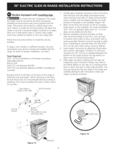
...floor and attach with the back and side edges positioned exactly where the back and sides of range will work in either wood or concrete. If range is being pushed back to solid floor. Slide range into the floor. 3. Models Equipped with Leveiin gLS To reduce the risk of tipping of the... is ever moved to a different location, the antitip brackets must be sure that screws do not penetrate electrical wiring or plumbing. Remove template and place brackets on floor with the range. Brackets must also be moved and installed with body sides) Figure 13 SlideBack 12 Figure 14 When fastening...
...floor and attach with the back and side edges positioned exactly where the back and sides of range will work in either wood or concrete. If range is being pushed back to solid floor. Slide range into the floor. 3. Models Equipped with Leveiin gLS To reduce the risk of tipping of the... is ever moved to a different location, the antitip brackets must be sure that screws do not penetrate electrical wiring or plumbing. Remove template and place brackets on floor with the range. Brackets must also be moved and installed with body sides) Figure 13 SlideBack 12 Figure 14 When fastening...


