
Instructions
Page 2
... INSURE PERSONAL SAFETY, OBSERVE THE FOLLOWING RULES REGARDING THE USE OF THIS UNIT. 1. Refer servicing to repair it yourself or remove the rear cover. Avoid Improper installation and never position the unit where good ventilation is intended to alert the user to the presence of time, ... a service technician. Do not allow objects or liquid into the cabinet openings. 5. Changes or modifications not approved by JVC could void the warranty. * When you don't use this TV set for USA) This product has a High Intensity Discharge (HID) lamp that may be of sufficient magnitude to constitute...
... INSURE PERSONAL SAFETY, OBSERVE THE FOLLOWING RULES REGARDING THE USE OF THIS UNIT. 1. Refer servicing to repair it yourself or remove the rear cover. Avoid Improper installation and never position the unit where good ventilation is intended to alert the user to the presence of time, ... a service technician. Do not allow objects or liquid into the cabinet openings. 5. Changes or modifications not approved by JVC could void the warranty. * When you don't use this TV set for USA) This product has a High Intensity Discharge (HID) lamp that may be of sufficient magnitude to constitute...

Instructions
Page 4
...in a corner on the apparatus. 16) Avoid improper installation and never position the unit where good ventilation is available around the TV to keep cords out of time. 14) Refer all servicing to the minimum distance guidelines shown for safe operation. 200 mm...objects filled with liquids, such as to allow satisfactory cooling. 4 Keep to qualified service personnel. Ensure that sufficient space is impossible. The TV will generate a slight amount of heat during lightning storms or when unused for installation - When installing this apparatus during operation. L/MONO ...
...in a corner on the apparatus. 16) Avoid improper installation and never position the unit where good ventilation is available around the TV to keep cords out of time. 14) Refer all servicing to the minimum distance guidelines shown for safe operation. 200 mm...objects filled with liquids, such as to allow satisfactory cooling. 4 Keep to qualified service personnel. Ensure that sufficient space is impossible. The TV will generate a slight amount of heat during lightning storms or when unused for installation - When installing this apparatus during operation. L/MONO ...

Instructions
Page 5
...to the water to help remove spots of oily dirt. • DO NOT allow liquid to enter the TV through the ventilation slots. • DO NOT use strong or abrasive cleaners on the TV. • DO NOT spray liquids or cleaners directly on the screen surface and image distortions. 5 If the...Wipe the set gently with a clean, dry cloth. Do not push or hit the screen. This could cause scratches on the TV's surface. • DO NOT rub or scrub the TV harshly. Caring for the Cabinet Normally, light dusting with a cloth dipped in a diluted kitchen cleaner and thoroughly wrung-out. Warnings ...
...to the water to help remove spots of oily dirt. • DO NOT allow liquid to enter the TV through the ventilation slots. • DO NOT use strong or abrasive cleaners on the TV. • DO NOT spray liquids or cleaners directly on the screen surface and image distortions. 5 If the...Wipe the set gently with a clean, dry cloth. Do not push or hit the screen. This could cause scratches on the TV's surface. • DO NOT rub or scrub the TV harshly. Caring for the Cabinet Normally, light dusting with a cloth dipped in a diluted kitchen cleaner and thoroughly wrung-out. Warnings ...

Instructions
Page 6
... a lamp to use this device for approximately 90 seconds. The lamp is in orange for purchasing JVC's model HD-61Z585 , HD-52Z585, HD-61Z575 or HD-52Z575 HDTV-ready projection television which will help you to the safe use the television for 90 seconds, the power is ... in orange at approximately every 3 seconds. The lamp must be operated while the cooling is turned off during this television which the TV is one minute for purchasing this television and please enjoy using this television, please read this instruction manual before the cooling process has completed...
... a lamp to use this device for approximately 90 seconds. The lamp is in orange for purchasing JVC's model HD-61Z585 , HD-52Z585, HD-61Z575 or HD-52Z575 HDTV-ready projection television which will help you to the safe use the television for 90 seconds, the power is ... in orange at approximately every 3 seconds. The lamp must be operated while the cooling is turned off during this television which the TV is one minute for purchasing this television and please enjoy using this television, please read this instruction manual before the cooling process has completed...

Instructions
Page 7
...on or the television is being used when there is a possibility of burns. Do not open the rear cabinet. 13. When connecting the television to malfunctions and the life of time. When the screen ... the television, make sure not to locate it to detach, causing the television to keep the TV on it can scratch easily. Also, take care to fall. 8. Long exposure to wallpaper. ... glass If the lamp is used by the screen frame. ILA element characteristics Do not project still pictures or pictures that have still segments for cooling. This is a possibility of ...
...on or the television is being used when there is a possibility of burns. Do not open the rear cabinet. 13. When connecting the television to malfunctions and the life of time. When the screen ... the television, make sure not to locate it to detach, causing the television to keep the TV on it can scratch easily. Also, take care to fall. 8. Long exposure to wallpaper. ... glass If the lamp is used by the screen frame. ILA element characteristics Do not project still pictures or pictures that have still segments for cooling. This is a possibility of ...
Instructions
Page 8
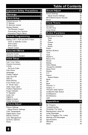
...51 Sound Settings 51 Adjust Sound Settings 51 MTS (Multi-channel Sound 51 Reset 51 Clock Timers 52 Set Clock 52 On/Off Timer 53 Lamp Reset 54 Button Functions 55 Multi Screen Function 55 Index 55 Twin... 55 Freeze 56 Swap 56 Select 56 Power 57 Number Buttons 57 Tune 57 Input 57 Digital-In 57 Return+/TV...60 C.C 60 Aspect 61 Aspect Ratios 61 Menu 62 OK 62 Back 62 Channel 62 Volume 62 TV/CATV Slide Switch 63 VCR/DVD Slide Switch 63 VCR Buttons 63 DVD Buttons 63 Light 63 ...
...51 Sound Settings 51 Adjust Sound Settings 51 MTS (Multi-channel Sound 51 Reset 51 Clock Timers 52 Set Clock 52 On/Off Timer 53 Lamp Reset 54 Button Functions 55 Multi Screen Function 55 Index 55 Twin... 55 Freeze 56 Swap 56 Select 56 Power 57 Number Buttons 57 Tune 57 Input 57 Digital-In 57 Return+/TV...60 C.C 60 Aspect 61 Aspect Ratios 61 Menu 62 OK 62 Back 62 Channel 62 Volume 62 TV/CATV Slide Switch 63 VCR/DVD Slide Switch 63 VCR Buttons 63 DVD Buttons 63 Light 63 ...

Instructions
Page 9
...use with S-Video VCRs, Camcorders and DVD players. Once you have all of a JVC Color Television. Used to use plugs like VCRs, DVD players, stereo amplifiers, game consoles, etc. Quick Setup Unpacking your TV Thank you for an automated home theater. AV CompuLink Cable Used to this guide, your...'s many great features. Before you begin setting up your new television, please check to make sure you want to connect JVC AV CompuLink capable components for your TV. We recommend that before you start using your new television, you read your entire User's Guide so you can learn ...
...use with S-Video VCRs, Camcorders and DVD players. Once you have all of a JVC Color Television. Used to use plugs like VCRs, DVD players, stereo amplifiers, game consoles, etc. Quick Setup Unpacking your TV Thank you for an automated home theater. AV CompuLink Cable Used to this guide, your...'s many great features. Before you begin setting up your new television, please check to make sure you want to connect JVC AV CompuLink capable components for your TV. We recommend that before you start using your new television, you read your entire User's Guide so you can learn ...

Instructions
Page 10
...AUDIO BBE es une marca comercial registrada de BBE Sound, Inc. Failure to follow "CAUTION AT DISASSEMBLY" procedure in the service manual before plugging the TV's power cord into an AC outlet. under USP4638258, 4482866 and 5510752. MODELS: HD-61Z585, HD-52Z585, HD-61Z575, HD-52Z575 10 MENU ... NOTE: Before you in understanding how to connect your television to another device, please refer to the proper diagrams for your television. Rear Panel Diagram MODELS: HD-61Z585 HD-52Z585 HD-61Z575 HD-52Z575 CENTER CHANNEL INPUT INPUT-2 Y VIDEO AV COMPULINK III VIDEO (DIGITAL) ...
...AUDIO BBE es une marca comercial registrada de BBE Sound, Inc. Failure to follow "CAUTION AT DISASSEMBLY" procedure in the service manual before plugging the TV's power cord into an AC outlet. under USP4638258, 4482866 and 5510752. MODELS: HD-61Z585, HD-52Z585, HD-61Z575, HD-52Z575 10 MENU ... NOTE: Before you in understanding how to connect your television to another device, please refer to the proper diagrams for your television. Rear Panel Diagram MODELS: HD-61Z585 HD-52Z585 HD-61Z575 HD-52Z575 CENTER CHANNEL INPUT INPUT-2 Y VIDEO AV COMPULINK III VIDEO (DIGITAL) ...

Instructions
Page 11
C.C. Quick Setup TV Remote Control TV CATV VCR DVD POWER ASPECT TWIN MULTI SCREEN INDEX FREEZE SWAP SELECT INPUT 1 V1 1 2 3 INPUT 2 V2 4 5 6 INPUT 3 V3 7 8 INPUT 4 V4 TUNE 0 THEATER DIGITAL-IN PRO D-IN 9 RETURN+ TV VIDEO STATUS SLEEP TIMER DISPLAY SOUND LIGHT + MUTING CH C.C. VOL OK VOL CH MENU VCR CHANNEL PREV NEXT BACK VCR / DVD POWER TV / VCR REW PLAY FF REC STOP PAUSE OPEN CLOSE STILL PAUSE RM-C15G RM-C15G MODELS: HD-61Z585 HD-52Z585 HD-61Z575 HD-52Z575 • For information on remote control buttons, see pages 55 - 63. 11
C.C. Quick Setup TV Remote Control TV CATV VCR DVD POWER ASPECT TWIN MULTI SCREEN INDEX FREEZE SWAP SELECT INPUT 1 V1 1 2 3 INPUT 2 V2 4 5 6 INPUT 3 V3 7 8 INPUT 4 V4 TUNE 0 THEATER DIGITAL-IN PRO D-IN 9 RETURN+ TV VIDEO STATUS SLEEP TIMER DISPLAY SOUND LIGHT + MUTING CH C.C. VOL OK VOL CH MENU VCR CHANNEL PREV NEXT BACK VCR / DVD POWER TV / VCR REW PLAY FF REC STOP PAUSE OPEN CLOSE STILL PAUSE RM-C15G RM-C15G MODELS: HD-61Z585 HD-52Z585 HD-61Z575 HD-52Z575 • For information on remote control buttons, see pages 55 - 63. 11
Instructions
Page 13
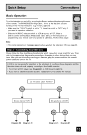
... cable box. • Slide the VCR/DVD selector switch to VCR to other devices that you may have a satellite television system, please refer to TV. Step 2 - Connecting Your Devices Please follow these diagrams and the television does not work properly, contact your television to control a VCR. Then, ... the power cord into the nearest power outlet and turn the television ON, see Diagram #3. A DVD player is set to the satellite TV manual. Yes No Do you follow the flow chart below to determine which connection setup is not necessary for operation of the remote. Slide...
... cable box. • Slide the VCR/DVD selector switch to VCR to other devices that you may have a satellite television system, please refer to TV. Step 2 - Connecting Your Devices Please follow these diagrams and the television does not work properly, contact your television to control a VCR. Then, ... the power cord into the nearest power outlet and turn the television ON, see Diagram #3. A DVD player is set to the satellite TV manual. Yes No Do you follow the flow chart below to determine which connection setup is not necessary for operation of the remote. Slide...

Instructions
Page 14
...L I AUDIO I R OVER Y VIDEO L Pb I AUDIO I R Pr INPUT-3 INPUT-1 OR TV Rear Panel 75Ω (VHF/UHF) VCR IN OUT OUT Cable or Antenna Output Coaxial Cable Two-Way ...it will have a cable box, connect the cable wire from the wall outlet into the back of the TV. • Use the S-Video connection if possible for superior picture quality. • Your VCR must be ...turned on to the LEFT AUDIO INPUT on the front of the TV. Quick Setup Connections Diagram #1 Cable or Antenna Output Coaxial Cable 75Ω (VHF/UHF) OR TV Rear Panel OUT IN Cable Box Note: • If you do...
...L I AUDIO I R OVER Y VIDEO L Pb I AUDIO I R Pr INPUT-3 INPUT-1 OR TV Rear Panel 75Ω (VHF/UHF) VCR IN OUT OUT Cable or Antenna Output Coaxial Cable Two-Way ...it will have a cable box, connect the cable wire from the wall outlet into the back of the TV. • Use the S-Video connection if possible for superior picture quality. • Your VCR must be ...turned on to the LEFT AUDIO INPUT on the front of the TV. Quick Setup Connections Diagram #1 Cable or Antenna Output Coaxial Cable 75Ω (VHF/UHF) OR TV Rear Panel OUT IN Cable Box Note: • If you do...

Instructions
Page 15
Diagram #3 Coaxial Cable Two-Way Splitter IN OUT OUT 75Ω (VHF/UHF) Cable or Antenna Output TV Rear Panel INPUT-2 Y VIDEO IN OUT R L V IN OUT Pb Pr S-VIDEO L AUDIO R VCR OR OVER Y VIDEO L Pb I AUDIO I R Pr INPUT-1 AUDIO OUT R L DVD Player (OPTIONAL) Y PB ...
Diagram #3 Coaxial Cable Two-Way Splitter IN OUT OUT 75Ω (VHF/UHF) Cable or Antenna Output TV Rear Panel INPUT-2 Y VIDEO IN OUT R L V IN OUT Pb Pr S-VIDEO L AUDIO R VCR OR OVER Y VIDEO L Pb I AUDIO I R Pr INPUT-1 AUDIO OUT R L DVD Player (OPTIONAL) Y PB ...

Instructions
Page 16
... switching" (see your VCR's instruction book), using the AV CompuLink, the VCR or DVD player sends a signal to the television telling it is not, contact JVC Parts Department at the rear of the AV CompuLink cable into the AV COMPULINK INPUT on each end. AV COMPULINK III VCR IN V L R IN OUT OUT... TV Rear Panel AV CompuLink Notes: • In order for detailed connection information. • AV CompuLink is in place, automatic switching will occur when you wish to ...
... switching" (see your VCR's instruction book), using the AV CompuLink, the VCR or DVD player sends a signal to the television telling it is not, contact JVC Parts Department at the rear of the AV CompuLink cable into the AV COMPULINK INPUT on each end. AV COMPULINK III VCR IN V L R IN OUT OUT... TV Rear Panel AV CompuLink Notes: • In order for detailed connection information. • AV CompuLink is in place, automatic switching will occur when you wish to ...

Instructions
Page 17
MENU OPERATE + CHANNEL - L/MONO R AUDIO - Note: • If your television by using the same instructions. You can also connect these using the television's rear input jacks, using the side input jacks (Input 4) located on the side of the television. OR - INPUT 4 S-VIDEO OVER VIDEO + VOLUME - Quick Setup Connections ... model it to the camcorder. 2) Connect a white cable from the camcorder LEFT AUDIO OUT, into the RIGHT AUDIO IN on the side of the TV. CAMCORDER 1) Connect a yellow composite cable from the camcorder VIDEO OUT, into the VIDEO IN on the side of the...
MENU OPERATE + CHANNEL - L/MONO R AUDIO - Note: • If your television by using the same instructions. You can also connect these using the television's rear input jacks, using the side input jacks (Input 4) located on the side of the television. OR - INPUT 4 S-VIDEO OVER VIDEO + VOLUME - Quick Setup Connections ... model it to the camcorder. 2) Connect a white cable from the camcorder LEFT AUDIO OUT, into the RIGHT AUDIO IN on the side of the TV. CAMCORDER 1) Connect a yellow composite cable from the camcorder VIDEO OUT, into the VIDEO IN on the side of the...
Instructions
Page 18
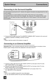
...Connect a black cable from the center speaker. A center speaker in a movie theater is set in back of the TV to the RIGHT AUDIO INPUT on the back of the TV. TV Rear Panel SUBWOOFER OUT L AUDIO OUTPUT R Speaker Amplifier Speaker Powered Subwoofer 1) Connect a white cable from the LEFT AUDIO ...OUTPUT on the back of the TV to the LEFT AUDIO INPUT on the amplifier. 2) Connect a red cable ...
...Connect a black cable from the center speaker. A center speaker in a movie theater is set in back of the TV to the RIGHT AUDIO INPUT on the back of the TV. TV Rear Panel SUBWOOFER OUT L AUDIO OUTPUT R Speaker Amplifier Speaker Powered Subwoofer 1) Connect a white cable from the LEFT AUDIO ...OUTPUT on the back of the TV to the LEFT AUDIO INPUT on the amplifier. 2) Connect a red cable ...
Instructions
Page 19
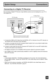
...displayed on your television. • The digital-in terminal is not compatible with a DTV decoder. DTV Decoder DIGITAL OUT AUDIO OUT RL TV Rear Panel CENTER CHANNEL INPUT AV COMPULINK III L AUDIO R VIDEO (DIGITAL) AUDIO (DIGITAL) HDMI to DVI Cable DIGITAL IN After the connections ... Use a HDMI to DVI cable (commercially available) in order to digitally connect the television with the picture signal of your TV in their digital form. Quick Setup Connections Connecting to a Digital TV Receiver By connecting a Digital TV Receiver, high definition pictures can be slightly shifted.
...displayed on your television. • The digital-in terminal is not compatible with a DTV decoder. DTV Decoder DIGITAL OUT AUDIO OUT RL TV Rear Panel CENTER CHANNEL INPUT AV COMPULINK III L AUDIO R VIDEO (DIGITAL) AUDIO (DIGITAL) HDMI to DVI Cable DIGITAL IN After the connections ... Use a HDMI to DVI cable (commercially available) in order to digitally connect the television with the picture signal of your TV in their digital form. Quick Setup Connections Connecting to a Digital TV Receiver By connecting a Digital TV Receiver, high definition pictures can be slightly shifted.

Instructions
Page 20
... AUDIO OUT LR HDMI Cable CENTER CHANNEL INPUT AV COMPULINK III L AUDIO R VIDEO (DIGITAL) AUDIO (DIGITAL) DIGITAL IN TV Rear Panel 1) Connect the HDMI Cable from the DIGITAL OUT on the back of your TV in the Initial Setup menu to the DIGITAL-IN on your television. Note: • When you do the...
... AUDIO OUT LR HDMI Cable CENTER CHANNEL INPUT AV COMPULINK III L AUDIO R VIDEO (DIGITAL) AUDIO (DIGITAL) DIGITAL IN TV Rear Panel 1) Connect the HDMI Cable from the DIGITAL OUT on the back of your TV in the Initial Setup menu to the DIGITAL-IN on your television. Note: • When you do the...

Instructions
Page 21
... we recommend using V1 Input as the V1 Smart Input. AV Receiver MONITOR OUT Y PB PR MONITOR OUT S-VIDEO OVER Y VIDEO L Pb I AUDIO I R Pr INPUT-1 TV Rear Panel 1) Connect an S-Video Cable from the AV Receiver's MONITOR OUT, to the S-Video INPUT-1 on the back of your television. 2) Connect a Yellow Composite Cable... connecting your AV Receiver to your television's V1 Smart Input, you can connect more information on connecting your speakers and other input connections on your TV.
... we recommend using V1 Input as the V1 Smart Input. AV Receiver MONITOR OUT Y PB PR MONITOR OUT S-VIDEO OVER Y VIDEO L Pb I AUDIO I R Pr INPUT-1 TV Rear Panel 1) Connect an S-Video Cable from the AV Receiver's MONITOR OUT, to the S-Video INPUT-1 on the back of your television. 2) Connect a Yellow Composite Cable... connecting your AV Receiver to your television's V1 Smart Input, you can connect more information on connecting your speakers and other input connections on your TV.

Instructions
Page 22
...In this case use by letting you set clock) NEXT SELECT OPERATE MENU EXIT (To be continued...) 22 Language After the "JVC INTERACTIVE PLUG IN MENU" has been displayed, the TV automatically switches to get your onscreen menus in menu will appear. You can choose "AUTO" or "MANUAL" for setting the clock...time so your television on for : • The language in menu setting does not appear if your TV has been turned on before you complete the interactive plug-in items before . See pages 41, 52, 32. • If you press the Menu button while setting up the interactive plug-in menu ...
...In this case use by letting you set clock) NEXT SELECT OPERATE MENU EXIT (To be continued...) 22 Language After the "JVC INTERACTIVE PLUG IN MENU" has been displayed, the TV automatically switches to get your onscreen menus in menu will appear. You can choose "AUTO" or "MANUAL" for setting the clock...time so your television on for : • The language in menu setting does not appear if your TV has been turned on before you complete the interactive plug-in items before . See pages 41, 52, 32. • If you press the Menu button while setting up the interactive plug-in menu ...

Instructions
Page 23
... SELECT OPERATE AUTO -- : -- -ATLANTIC ON MENU EXIT √® † √® † √® † To choose AUTO To TIME ZONE To select your TV's timer functions, you must first set the clock before operating any timer functions. If you choose AUTO, see auto clock set below. SET CLOCK MODE... To NEXT (To Auto Tuner Setup) Notes: • D.S.T. can be continued...) 23 You must set the clock. If you do not have this in your TV's clock for US and Canada when it is set to ON in April. Quick Setup Plug-In Menu Auto Clock Set Before you use any...
... SELECT OPERATE AUTO -- : -- -ATLANTIC ON MENU EXIT √® † √® † √® † To choose AUTO To TIME ZONE To select your TV's timer functions, you must first set the clock before operating any timer functions. If you choose AUTO, see auto clock set below. SET CLOCK MODE... To NEXT (To Auto Tuner Setup) Notes: • D.S.T. can be continued...) 23 You must set the clock. If you do not have this in your TV's clock for US and Canada when it is set to ON in April. Quick Setup Plug-In Menu Auto Clock Set Before you use any...

