
Instructions
Page 2
Refer servicing to repair it yourself or remove the rear cover. Avoid damaging the AC plug and power cord. 3. For disposal or recycling information, please contact your safety. * To prevent electric shock do not use ... TO RAIN OR MOISTURE. Do not attempt to qualified service personnel. Changes or modifications not approved by JVC could void the warranty. * When you don't use this TV set for a long period of these materials may be fully inserted to prevent blade exposure. Disposal of time, be regulated in some components. Do...
Refer servicing to repair it yourself or remove the rear cover. Avoid damaging the AC plug and power cord. 3. For disposal or recycling information, please contact your safety. * To prevent electric shock do not use ... TO RAIN OR MOISTURE. Do not attempt to qualified service personnel. Changes or modifications not approved by JVC could void the warranty. * When you don't use this TV set for a long period of these materials may be fully inserted to prevent blade exposure. Disposal of time, be regulated in some components. Do...

Instructions
Page 4
...exposed to rain or moisture, does not operate normally, or has been dropped. 15) Apparatus shall not be exposed to qualified service personnel. The TV will generate a slight amount of heat during lightning storms or when unused for long periods of time. 14) Refer all servicing to dripping or ...and no objects filled with liquids, such as vases, shall be placed on the floor so as to allow satisfactory cooling. 4 13) Unplug this TV, distance recommendations must be maintained between the set and the wall, as well as inside a tightly enclosed area or piece of furniture. When installing ...
...exposed to rain or moisture, does not operate normally, or has been dropped. 15) Apparatus shall not be exposed to qualified service personnel. The TV will generate a slight amount of heat during lightning storms or when unused for long periods of time. 14) Refer all servicing to dripping or ...and no objects filled with liquids, such as vases, shall be placed on the floor so as to allow satisfactory cooling. 4 13) Unplug this TV, distance recommendations must be maintained between the set and the wall, as well as inside a tightly enclosed area or piece of furniture. When installing ...

Instructions
Page 5
... and cause discolorations. Do not apply alcohol, organic solvents (like acetone), acidic or alkaline cleansers to enter the TV through the ventilation slots. • DO NOT use strong or abrasive cleaners on the TV. • DO NOT spray liquids or cleaners directly on the screen surface and image distortions. 5 These will keep... your TV clean. You can add a few drops of mild liquid detergent to the water to help remove spots of oily dirt. • DO NOT allow liquid ...
... and cause discolorations. Do not apply alcohol, organic solvents (like acetone), acidic or alkaline cleansers to enter the TV through the ventilation slots. • DO NOT use strong or abrasive cleaners on the TV. • DO NOT spray liquids or cleaners directly on the screen surface and image distortions. 5 These will keep... your TV clean. You can add a few drops of mild liquid detergent to the water to help remove spots of oily dirt. • DO NOT allow liquid ...

Instructions
Page 6
...2. When the power is turned on . Note: It is impossible to turn off , the picture on the atmospheric temperature and altitude in which the TV is being used as a guide. After 1 or more minutes have passed, you read the safety cautions and information about it has blown or when ... for approximately 90 seconds. The life of the device and important information which will help you for purchasing JVC's model HD-61Z585 , HD-52Z585, HD-61Z575 or HD-52Z575 HDTV-ready projection television which are performed. When the POWER button is pressed, the Lamp LED indicator blinks in orange for...
...2. When the power is turned on . Note: It is impossible to turn off , the picture on the atmospheric temperature and altitude in which the TV is being used as a guide. After 1 or more minutes have passed, you read the safety cautions and information about it has blown or when ... for approximately 90 seconds. The life of the device and important information which will help you for purchasing JVC's model HD-61Z585 , HD-52Z585, HD-61Z575 or HD-52Z575 HDTV-ready projection television which are performed. When the POWER button is pressed, the Lamp LED indicator blinks in orange for...

Instructions
Page 7
... for more than 24 hours consecutively. The duct will blow warm air while the television is dirty, gently wipe it has a chance to keep the TV on the lamp glass, there is being shortened. 7 Also, take care to cool down, there is a possibility of the life of burns. If...Handle the screen very carefully as it with a soft cloth. ILA element characteristics Do not project still pictures or pictures that the television is made of the socket. Warnings 4. Please do not open the rear cabinet of this case, wait until the condensation has gone before it with any hard ...
... for more than 24 hours consecutively. The duct will blow warm air while the television is dirty, gently wipe it has a chance to keep the TV on the lamp glass, there is being shortened. 7 Also, take care to cool down, there is a possibility of the life of burns. If...Handle the screen very carefully as it with a soft cloth. ILA element characteristics Do not project still pictures or pictures that the television is made of the socket. Warnings 4. Please do not open the rear cabinet of this case, wait until the condensation has gone before it with any hard ...
Instructions
Page 8
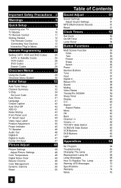
...51 Sound Settings 51 Adjust Sound Settings 51 MTS (Multi-channel Sound 51 Reset 51 Clock Timers 52 Set Clock 52 On/Off Timer 53 Lamp Reset 54 Button Functions 55 Multi Screen Function 55 Index 55 Twin... 55 Freeze 56 Swap 56 Select 56 Power 57 Number Buttons 57 Tune 57 Input 57 Digital-In 57 Return+/TV...60 C.C 60 Aspect 61 Aspect Ratios 61 Menu 62 OK 62 Back 62 Channel 62 Volume 62 TV/CATV Slide Switch 63 VCR/DVD Slide Switch 63 VCR Buttons 63 DVD Buttons 63 Light 63 ...
...51 Sound Settings 51 Adjust Sound Settings 51 MTS (Multi-channel Sound 51 Reset 51 Clock Timers 52 Set Clock 52 On/Off Timer 53 Lamp Reset 54 Button Functions 55 Multi Screen Function 55 Index 55 Twin... 55 Freeze 56 Swap 56 Select 56 Power 57 Number Buttons 57 Tune 57 Input 57 Digital-In 57 Return+/TV...60 C.C 60 Aspect 61 Aspect Ratios 61 Menu 62 OK 62 Back 62 Channel 62 Volume 62 TV/CATV Slide Switch 63 VCR/DVD Slide Switch 63 VCR Buttons 63 DVD Buttons 63 Light 63 ...

Instructions
Page 9
... connections with your television. VOL OK VOL Note: Your television CH MENU BACK and/or remote VCR CHANNEL VCR / DVD PREV NEXT POWER TV / VCR REW PLAY FF control may differ PROGRAM POWER REC STOP PAUSE OPEN CLOSE STILL PAUSE from the examples RM-C15G illustrated here. AV... the next step is to connect it to your antenna/ cable or satellite system and to connect the audio/video devices you want to connect JVC AV CompuLink capable components for your purchase of the following items. In addition to this guide, your television box should include: 1 Television 1 Remote...
... connections with your television. VOL OK VOL Note: Your television CH MENU BACK and/or remote VCR CHANNEL VCR / DVD PREV NEXT POWER TV / VCR REW PLAY FF control may differ PROGRAM POWER REC STOP PAUSE OPEN CLOSE STILL PAUSE from the examples RM-C15G illustrated here. AV... the next step is to connect it to your antenna/ cable or satellite system and to connect the audio/video devices you want to connect JVC AV CompuLink capable components for your purchase of the following items. In addition to this guide, your television box should include: 1 Television 1 Remote...

Instructions
Page 10
... • For information on the LED, see page 72. Failure to follow "CAUTION AT DISASSEMBLY" procedure in the service manual before plugging the TV's power cord into an AC outlet. Une fois le couvercle arrière déposé suivez l procédure « ATTENTION LORS...-52Z585, HD-61Z575, HD-52Z575 10 MENU OPERATE + CHANNEL - AVANT DE RETIRER LE COUVERCLE ARRIÈRE. INPUT 4 S-VIDEO OVER VIDEO + VOLUME - Rear Panel Diagram MODELS: HD-61Z585 HD-52Z585 HD-61Z575 HD-52Z575 CENTER CHANNEL INPUT INPUT-2 Y VIDEO AV COMPULINK III VIDEO (DIGITAL) AUDIO (DIGITAL) DIGITAL IN...
... • For information on the LED, see page 72. Failure to follow "CAUTION AT DISASSEMBLY" procedure in the service manual before plugging the TV's power cord into an AC outlet. Une fois le couvercle arrière déposé suivez l procédure « ATTENTION LORS...-52Z585, HD-61Z575, HD-52Z575 10 MENU OPERATE + CHANNEL - AVANT DE RETIRER LE COUVERCLE ARRIÈRE. INPUT 4 S-VIDEO OVER VIDEO + VOLUME - Rear Panel Diagram MODELS: HD-61Z585 HD-52Z585 HD-61Z575 HD-52Z575 CENTER CHANNEL INPUT INPUT-2 Y VIDEO AV COMPULINK III VIDEO (DIGITAL) AUDIO (DIGITAL) DIGITAL IN...

Instructions
Page 11
VOL OK VOL CH MENU VCR CHANNEL PREV NEXT BACK VCR / DVD POWER TV / VCR REW PLAY FF REC STOP PAUSE OPEN CLOSE STILL PAUSE RM-C15G RM-C15G MODELS: HD-61Z585 HD-52Z585 HD-61Z575 HD-52Z575 • For information on remote control buttons, see pages 55 - 63. 11 C.C. Quick Setup TV Remote Control TV CATV VCR DVD POWER ASPECT TWIN MULTI SCREEN INDEX FREEZE SWAP SELECT INPUT 1 V1 1 2 3 INPUT 2 V2 4 5 6 INPUT 3 V3 7 8 INPUT 4 V4 TUNE 0 THEATER DIGITAL-IN PRO D-IN 9 RETURN+ TV VIDEO STATUS SLEEP TIMER DISPLAY SOUND LIGHT + MUTING CH C.C.
VOL OK VOL CH MENU VCR CHANNEL PREV NEXT BACK VCR / DVD POWER TV / VCR REW PLAY FF REC STOP PAUSE OPEN CLOSE STILL PAUSE RM-C15G RM-C15G MODELS: HD-61Z585 HD-52Z585 HD-61Z575 HD-52Z575 • For information on remote control buttons, see pages 55 - 63. 11 C.C. Quick Setup TV Remote Control TV CATV VCR DVD POWER ASPECT TWIN MULTI SCREEN INDEX FREEZE SWAP SELECT INPUT 1 V1 1 2 3 INPUT 2 V2 4 5 6 INPUT 3 V3 7 8 INPUT 4 V4 TUNE 0 THEATER DIGITAL-IN PRO D-IN 9 RETURN+ TV VIDEO STATUS SLEEP TIMER DISPLAY SOUND LIGHT + MUTING CH C.C.
Instructions
Page 13
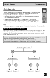
... Note: • If the lamp replacement message appears when you follow the flow chart below to TV. Step 2 - A VCR is right for you may have a VCR? If you turn on the TV. Quick Setup Connections Basic Operation POWER T Turn the television on and off by pressing the POWER ... Your Devices Please follow these diagrams and the television does not work properly, contact your remote control to the satellite TV manual. Slide to DVD to CATV only if you use a Cable TV Box? Yes No Diagram #2 Diagram #1 Yes No Diagram #3 Diagram #1 13 Then, refer to the appropriate diagrams...
... Note: • If the lamp replacement message appears when you follow the flow chart below to TV. Step 2 - A VCR is right for you may have a VCR? If you turn on the TV. Quick Setup Connections Basic Operation POWER T Turn the television on and off by pressing the POWER ... Your Devices Please follow these diagrams and the television does not work properly, contact your remote control to the satellite TV manual. Slide to DVD to CATV only if you use a Cable TV Box? Yes No Diagram #2 Diagram #1 Yes No Diagram #3 Diagram #1 13 Then, refer to the appropriate diagrams...

Instructions
Page 14
... must be turned on to view premium cable channels. 14 Quick Setup Connections Diagram #1 Cable or Antenna Output Coaxial Cable 75Ω (VHF/UHF) OR TV Rear Panel OUT IN Cable Box Note: • If you do not have only one audio out jack. Diagram #2 S-VIDEO S-VIDEO OVER VIDEO L I AUDIO ...I R OVER Y VIDEO L Pb I AUDIO I R Pr INPUT-3 INPUT-1 OR TV Rear Panel 75Ω (VHF/UHF) VCR IN OUT OUT Cable or Antenna Output Coaxial Cable Two-Way Splitter IN IN OUT R LV OUT OUT IN...
... must be turned on to view premium cable channels. 14 Quick Setup Connections Diagram #1 Cable or Antenna Output Coaxial Cable 75Ω (VHF/UHF) OR TV Rear Panel OUT IN Cable Box Note: • If you do not have only one audio out jack. Diagram #2 S-VIDEO S-VIDEO OVER VIDEO L I AUDIO ...I R OVER Y VIDEO L Pb I AUDIO I R Pr INPUT-3 INPUT-1 OR TV Rear Panel 75Ω (VHF/UHF) VCR IN OUT OUT Cable or Antenna Output Coaxial Cable Two-Way Splitter IN IN OUT R LV OUT OUT IN...

Instructions
Page 15
... red DVD cable with the red audio cable. Diagram #3 Coaxial Cable Two-Way Splitter IN OUT OUT 75Ω (VHF/UHF) Cable or Antenna Output TV Rear Panel INPUT-2 Y VIDEO IN OUT R L V IN OUT Pb Pr S-VIDEO L AUDIO R VCR OR OVER Y VIDEO L Pb I AUDIO I R Pr INPUT-1 AUDIO OUT R L DVD Player (OPTIONAL) Y PB...
... red DVD cable with the red audio cable. Diagram #3 Coaxial Cable Two-Way Splitter IN OUT OUT 75Ω (VHF/UHF) Cable or Antenna Output TV Rear Panel INPUT-2 Y VIDEO IN OUT R L V IN OUT Pb Pr S-VIDEO L AUDIO R VCR OR OVER Y VIDEO L Pb I AUDIO I R Pr INPUT-1 AUDIO OUT R L DVD Player (OPTIONAL) Y PB...

Instructions
Page 16
...see your VCR, DVD, or other end of the television. If it to JVC AV Compu Link JVC's AV CompuLink feature makes playing video tapes or DVDs totally automatic. AV COMPULINK III VCR IN V L R IN OUT OUT TV Rear Panel AV CompuLink Notes: • In order for the VCR playback to your... JVC DVD player and the device will switch the TV to input 1. • Refer to begin playback. Note: • The AV CompuLink cable...
...see your VCR, DVD, or other end of the television. If it to JVC AV Compu Link JVC's AV CompuLink feature makes playing video tapes or DVDs totally automatic. AV COMPULINK III VCR IN V L R IN OUT OUT TV Rear Panel AV CompuLink Notes: • In order for the VCR playback to your... JVC DVD player and the device will switch the TV to input 1. • Refer to begin playback. Note: • The AV CompuLink cable...

Instructions
Page 17
... a red cable from the camcorder RIGHT AUDIO OUT, into the RIGHT AUDIO IN on the side of the TV. You can also connect these using the television's rear input jacks, using the side input jacks (Input 4) located on the side of the television. MENU OPERATE + CHANNEL - OR - CAMCORDER 1)... Connect a yellow composite cable from the camcorder VIDEO OUT, into the VIDEO IN on the side of the TV, OR connect an S-...
... a red cable from the camcorder RIGHT AUDIO OUT, into the RIGHT AUDIO IN on the side of the TV. You can also connect these using the television's rear input jacks, using the side input jacks (Input 4) located on the side of the television. MENU OPERATE + CHANNEL - OR - CAMCORDER 1)... Connect a yellow composite cable from the camcorder VIDEO OUT, into the VIDEO IN on the side of the TV, OR connect an S-...
Instructions
Page 18
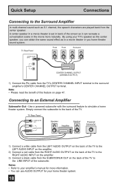
... your home theater system. 18 Notes: • Refer to your amplifier's manual for more naturally. Connecting to simulate a home theater system. TV Rear Panel SUBWOOFER OUT L AUDIO OUTPUT R Speaker Amplifier Speaker Powered Subwoofer 1) Connect a white cable from the LEFT AUDIO OUTPUT on the back of the... the LEFT AUDIO INPUT on the amplifier. 2) Connect a red cable from the RIGHT AUDIO OUTPUT on the back of the TV. TV Rear Panel Front Front Surround CENTER CHANNEL INPUT L AUDIO R CENTER CHANNEL OUTPUT (VARIABLE OUTPUT) 1) Connect the Pin cable from the SUBWOOFER OUT ...
... your home theater system. 18 Notes: • Refer to your amplifier's manual for more naturally. Connecting to simulate a home theater system. TV Rear Panel SUBWOOFER OUT L AUDIO OUTPUT R Speaker Amplifier Speaker Powered Subwoofer 1) Connect a white cable from the LEFT AUDIO OUTPUT on the back of the... the LEFT AUDIO INPUT on the amplifier. 2) Connect a red cable from the RIGHT AUDIO OUTPUT on the back of the TV. TV Rear Panel Front Front Surround CENTER CHANNEL INPUT L AUDIO R CENTER CHANNEL OUTPUT (VARIABLE OUTPUT) 1) Connect the Pin cable from the SUBWOOFER OUT ...
Instructions
Page 19
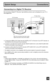
... to page 47.) • When you do the above connection, set DIGITAL-IN AUDIO in their digital form. DTV Decoder DIGITAL OUT AUDIO OUT RL TV Rear Panel CENTER CHANNEL INPUT AV COMPULINK III L AUDIO R VIDEO (DIGITAL) AUDIO (DIGITAL) HDMI to DVI Cable DIGITAL IN After the connections have been made, tighten... AUDIO OUT, to the LEFT AUDIO DIGITAL-IN on your television. • The digital-in terminal is not compatible with the picture signal of your TV in the Initial Setup menu to ANALOG. Quick Setup Connections Connecting to a Digital...
... to page 47.) • When you do the above connection, set DIGITAL-IN AUDIO in their digital form. DTV Decoder DIGITAL OUT AUDIO OUT RL TV Rear Panel CENTER CHANNEL INPUT AV COMPULINK III L AUDIO R VIDEO (DIGITAL) AUDIO (DIGITAL) HDMI to DVI Cable DIGITAL IN After the connections have been made, tighten... AUDIO OUT, to the LEFT AUDIO DIGITAL-IN on your television. • The digital-in terminal is not compatible with the picture signal of your TV in the Initial Setup menu to ANALOG. Quick Setup Connections Connecting to a Digital...

Instructions
Page 20
... HDMI Compatible Device DIGITAL OUT AUDIO OUT LR HDMI Cable CENTER CHANNEL INPUT AV COMPULINK III L AUDIO R VIDEO (DIGITAL) AUDIO (DIGITAL) DIGITAL IN TV Rear Panel 1) Connect the HDMI Cable from the DIGITAL OUT on the back of your DTV or HDMI device, to a HDMI Compatible Device By connecting ... video monitor, such as a set DIGITAL-IN AUDIO in their digital form. Some HDMI devices can be displayed on the back of your TV in the Initial Setup menu to DIGITAL. HDMI provides and interface between any HDMI compatible device. HDMI (High Definition Multimedia Interface) is the...
... HDMI Compatible Device DIGITAL OUT AUDIO OUT LR HDMI Cable CENTER CHANNEL INPUT AV COMPULINK III L AUDIO R VIDEO (DIGITAL) AUDIO (DIGITAL) DIGITAL IN TV Rear Panel 1) Connect the HDMI Cable from the DIGITAL OUT on the back of your DTV or HDMI device, to a HDMI Compatible Device By connecting ... video monitor, such as a set DIGITAL-IN AUDIO in their digital form. Some HDMI devices can be displayed on the back of your TV in the Initial Setup menu to DIGITAL. HDMI provides and interface between any HDMI compatible device. HDMI (High Definition Multimedia Interface) is the...

Instructions
Page 21
... using V1 Input as the V1 Smart Input. AV Receiver MONITOR OUT Y PB PR MONITOR OUT S-VIDEO OVER Y VIDEO L Pb I AUDIO I R Pr INPUT-1 TV Rear Panel 1) Connect an S-Video Cable from the AV Receiver's MONITOR OUT, to the S-Video INPUT-1 on the back of your television. 2) Connect a Yellow Composite Cable...the other input connections so you can watch picture sources from the AV Receiver's PR MONITOR OUT, into the Pr VIDEO INPUT-1 on your TV. This allows you to your television. In this case we recommend using both S-Video and Composite connection at the same time when you can...
... using V1 Input as the V1 Smart Input. AV Receiver MONITOR OUT Y PB PR MONITOR OUT S-VIDEO OVER Y VIDEO L Pb I AUDIO I R Pr INPUT-1 TV Rear Panel 1) Connect an S-Video Cable from the AV Receiver's MONITOR OUT, to the S-Video INPUT-1 on the back of your television. 2) Connect a Yellow Composite Cable...the other input connections so you can watch picture sources from the AV Receiver's PR MONITOR OUT, into the Pr VIDEO INPUT-1 on your TV. This allows you to your television. In this case we recommend using both S-Video and Composite connection at the same time when you can...

Instructions
Page 22
You can choose to the LANGUAGE settings. See pages 41, 52, 32. • If you turn your timer functions will work properly. Notes: • The interactive plug-in menu setting does not appear if your TV has been turned on for the first time the interactive plug-in which channels ... plug-in three languages: English, French (Français) or Spanish (Español). Language After the "JVC INTERACTIVE PLUG IN MENU" has been displayed, the TV automatically switches to view your TV ready to use the onscreen menus to receive. Quick Setup Plug-In Menu Step 3 - The plug-in items...
You can choose to the LANGUAGE settings. See pages 41, 52, 32. • If you turn your timer functions will work properly. Notes: • The interactive plug-in menu setting does not appear if your TV has been turned on for the first time the interactive plug-in which channels ... plug-in three languages: English, French (Français) or Spanish (Español). Language After the "JVC INTERACTIVE PLUG IN MENU" has been displayed, the TV automatically switches to view your TV ready to use the onscreen menus to receive. Quick Setup Plug-In Menu Step 3 - The plug-in items...

Instructions
Page 23
... do not have this in the SET CLOCK menu. • Only when the MODE set to AUTO, the Daylight Savings Time feature automatically adjusts your TV's clock for US and Canada when it is set to ON in your area, you will move forward one hour at 2:00 am on the... hour at 2:00 am on the last Sunday in April. MANUAL -- : -- -- Quick Setup Plug-In Menu Auto Clock Set Before you use any of your TV's timer functions, you choose AUTO, see auto clock set above. NEXT SELECT OPERATE AUTO -- : -- -ATLANTIC ON MENU EXIT √® † √® † √...
... do not have this in the SET CLOCK menu. • Only when the MODE set to AUTO, the Daylight Savings Time feature automatically adjusts your TV's clock for US and Canada when it is set to ON in your area, you will move forward one hour at 2:00 am on the... hour at 2:00 am on the last Sunday in April. MANUAL -- : -- -- Quick Setup Plug-In Menu Auto Clock Set Before you use any of your TV's timer functions, you choose AUTO, see auto clock set above. NEXT SELECT OPERATE AUTO -- : -- -ATLANTIC ON MENU EXIT √® † √® † √...

