Instructions
Page 1
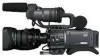
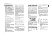
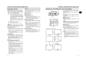
... on the body. LST0392- Serial No. * The illustration shows the GY-HD110/GYHD111 HD CAMERA RECORDER with the provided lens, viewfinder, microphone and battery pack attached. Before operating this information for purchasing this JVC product. Retain this unit, please read the instructions carefully to ensure the best possible performance. © 2006 Victor...
... on the body. LST0392- Serial No. * The illustration shows the GY-HD110/GYHD111 HD CAMERA RECORDER with the provided lens, viewfinder, microphone and battery pack attached. Before operating this information for purchasing this JVC product. Retain this unit, please read the instructions carefully to ensure the best possible performance. © 2006 Victor...
Instructions
Page 4
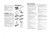
... during playback as a non-linear editing system. (Power cannot be supplied.) • 1/3" bayonet type lens • Camera output, VTR playback output (composite/component) possible • Built-in color bars (ARIB... GY-HD111E/CHE. HDV 720p (720 effective scan lines, progressive scan) HDV 1080i (1080 effective scan lines, interlaced scan) This camcorder supports HDV 720p format. (HDV 720p, 480p, 576p) HDV ...recording important scenes, be played back (simple playback). There are for purchasing the JVC GY-HD110U/CHU, GYHD110E/CHE and GY-HD111E/CHE HD CAMERA RECORDER. Thank you...
... during playback as a non-linear editing system. (Power cannot be supplied.) • 1/3" bayonet type lens • Camera output, VTR playback output (composite/component) possible • Built-in color bars (ARIB... GY-HD111E/CHE. HDV 720p (720 effective scan lines, progressive scan) HDV 1080i (1080 effective scan lines, interlaced scan) This camcorder supports HDV 720p format. (HDV 720p, 480p, 576p) HDV ...recording important scenes, be played back (simple playback). There are for purchasing the JVC GY-HD110U/CHU, GYHD110E/CHE and GY-HD111E/CHE HD CAMERA RECORDER. Thank you...
Instructions
Page 5
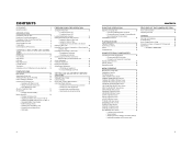
... of Head Cleaning Tape 7 Battery Pack to be Used 8 Videocassette to be Used 8 Condensation 9 Characteristic CCD Phenomena 9 CONTROLS, INDICATORS AND CONNECTORS ZOOM Lens 10 Front Section 11 Rear Section 12 LCD Door 13 Right Side Section 14 Left Side Section 16 Top Section 17 Indications on the LCD... Monitor and in the Viewfinder . . . . 19 PREPARATIONS Basic System 29 Attaching the Zoom Lens 30 Attaching the Microphone (Provided 30 How to Attach the Viewfinder 30 Inserting an SD Memory Card 31 • Inserting an SD Memory Card ...
... of Head Cleaning Tape 7 Battery Pack to be Used 8 Videocassette to be Used 8 Condensation 9 Characteristic CCD Phenomena 9 CONTROLS, INDICATORS AND CONNECTORS ZOOM Lens 10 Front Section 11 Rear Section 12 LCD Door 13 Right Side Section 14 Left Side Section 16 Top Section 17 Indications on the LCD... Monitor and in the Viewfinder . . . . 19 PREPARATIONS Basic System 29 Attaching the Zoom Lens 30 Attaching the Microphone (Provided 30 How to Attach the Viewfinder 30 Inserting an SD Memory Card 31 • Inserting an SD Memory Card ...
Instructions
Page 6
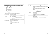
... near the camera When a wireless microphone or wireless microphone tuner is set lower than a videocassette in the viewfinder may occur at your nearest JVC-authorized service agent. Insert the cleaning tape. Running Low temperature Room temperature High temperature Operating envi- 0°C to 10°C ronment 10°...the camera after the tape has run as the indicator will turn off after use the camcorder continuously for 1 to 2 times ev- 1 to 2 times ev- 1 to Display the Hour Meter" on the lens section. In this may be sure to set the POWER switch to OFF or remove ...
... near the camera When a wireless microphone or wireless microphone tuner is set lower than a videocassette in the viewfinder may occur at your nearest JVC-authorized service agent. Insert the cleaning tape. Running Low temperature Room temperature High temperature Operating envi- 0°C to 10°C ronment 10°...the camera after the tape has run as the indicator will turn off after use the camcorder continuously for 1 to 2 times ev- 1 to 2 times ev- 1 to Display the Hour Meter" on the lens section. In this may be sure to set the POWER switch to OFF or remove ...
Instructions
Page 8
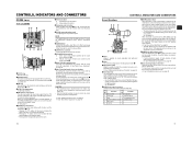
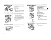
...LCD areas having luminance levels in the viewfinder. Function 1 Return switch 7 Iris position 2 VTR trigger 8 IRIS A/R INPUT 3 GND 9 EXTENDER position 4 Lens AUTO/MANU control 10 ZOOM position 5 IRIS control 11 - 6 +12V DC 12 - 6[ZEBRA] Zebra switch When this switch is ON, a zebra ...this button activates the Auto Iris Function while it possible to mount separately sold microphone. X See page 80. 5[LENS] Lens control connector Connect 12-pin lens control cable from the viewfinder, LCD monitor and video signal connector while this ring in the SWITCH MODE menu screen...
...LCD areas having luminance levels in the viewfinder. Function 1 Return switch 7 Iris position 2 VTR trigger 8 IRIS A/R INPUT 3 GND 9 EXTENDER position 4 Lens AUTO/MANU control 10 ZOOM position 5 IRIS control 11 - 6 +12V DC 12 - 6[ZEBRA] Zebra switch When this switch is ON, a zebra ...this button activates the Auto Iris Function while it possible to mount separately sold microphone. X See page 80. 5[LENS] Lens control connector Connect 12-pin lens control cable from the viewfinder, LCD monitor and video signal connector while this ring in the SWITCH MODE menu screen...
Instructions
Page 10
...-in A. B : Switch into white balance mode memorized in ND filter. X See page 71. e[POWER] Power ON/OFF switch Switch that the camcorder will be noisy. • When the FULL AUTO switch h on page 18. • The sound level is displayed in the LCD monitor or ... switch Electronically boosts the light sensitivity when there is pressed. A : Switch into white balance mode memorized in the viewfinder. dStand When attaching the lens, slide the stand forward. X See page 43. 14 15 X See "Alarm Sound" on again. The boosting level differs depending on the ...
...-in A. B : Switch into white balance mode memorized in ND filter. X See page 71. e[POWER] Power ON/OFF switch Switch that the camcorder will be noisy. • When the FULL AUTO switch h on page 18. • The sound level is displayed in the LCD monitor or ... switch Electronically boosts the light sensitivity when there is pressed. A : Switch into white balance mode memorized in the viewfinder. dStand When attaching the lens, slide the stand forward. X See page 43. 14 15 X See "Alarm Sound" on again. The boosting level differs depending on the ...
Instructions
Page 11
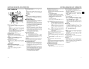
...device or microphone. • Set the [AUDIO INPUT] switch 9 according to the device to the side. item on the right panel and the lens VTR trigger button.) 9[REC LOCK] REC LOCK switch Slide this button during the eject operation. INPUT1 INPUT2 : Inputs the audio from the INPUT1 connector... MEMO • It takes a few seconds before the component is output in the video from the video signal output connector. Otherwise, keep this camcorder. • You can adjust the position of the viewfinder left or right by loosening this ring. 6Clamp Attach the microphone cable here. 7[FOCUS ...
...device or microphone. • Set the [AUDIO INPUT] switch 9 according to the device to the side. item on the right panel and the lens VTR trigger button.) 9[REC LOCK] REC LOCK switch Slide this button during the eject operation. INPUT1 INPUT2 : Inputs the audio from the INPUT1 connector... MEMO • It takes a few seconds before the component is output in the video from the video signal output connector. Otherwise, keep this camcorder. • You can adjust the position of the viewfinder left or right by loosening this ring. 6Clamp Attach the microphone cable here. 7[FOCUS ...
Instructions
Page 12
... is displayed to show characters on the LCD monitor, press the DISPLAY button briefly. X See page 66. • Auto iris mode operates even if the lens iris mode switch is set to rewind the tape. • Pressing this button during playback, in the stop mode. j[REW] Rewind button Press this button...
... is displayed to show characters on the LCD monitor, press the DISPLAY button briefly. X See page 66. • Auto iris mode operates even if the lens iris mode switch is set to rewind the tape. • Pressing this button during playback, in the stop mode. j[REW] Rewind button Press this button...
Instructions
Page 14
... information on the LCD/VF [2/3] menu screen. OPEN, F2, F2.8, F4, F5.6, F8, F11, F16, CLOSE It is not displayed when the lens is not indicated. The indication can switch this item is set with 12-bit, 32 kHz sampling.) 48 K : Indicated when the AUDIO MODE item ... no display appears. X See page 75. 7 Standard audio level indication The level at low temperatures, it may take a while before the indication of the connected lens. Remaining tape indication (displayed in - 32 K : Indicated when the AUDIO MODE item on the AUDIO/MIC [1/2] menu screen is indicated by "O". -20 dB,...
... information on the LCD/VF [2/3] menu screen. OPEN, F2, F2.8, F4, F5.6, F8, F11, F16, CLOSE It is not displayed when the lens is not indicated. The indication can switch this item is set with 12-bit, 32 kHz sampling.) 48 K : Indicated when the AUDIO MODE item ... no display appears. X See page 75. 7 Standard audio level indication The level at low temperatures, it may take a while before the indication of the connected lens. Remaining tape indication (displayed in - 32 K : Indicated when the AUDIO MODE item on the AUDIO/MIC [1/2] menu screen is indicated by "O". -20 dB,...

Instructions
Page 15
... 37, 43, 52, 65, or 80. Events are not displayed while these statuses are displayed during playback, fast forward, and rewind. Indication USER1 USER2 USER3 LENS RET Indication Contents NONE, BARS, PRESET TEMP., B.STRETCH1, B.STRETCH2, B.STRETCH3, B.COMPRESS1, B.COMPRESS2, B.COMPRESS3, AE LEVEL+, AE LEVEL-, RET NONE, BARS,... 2 3 4 5 6 7 0 9 8 No. A F symbol is displayed when a menu setting read from DV recording or playback is used only as LENS RET item on the video format. When the date and time have not been set on the TIME/DATE menu screen. CONTROLS, INDICATORS AND CONNECTORS...
... 37, 43, 52, 65, or 80. Events are not displayed while these statuses are displayed during playback, fast forward, and rewind. Indication USER1 USER2 USER3 LENS RET Indication Contents NONE, BARS, PRESET TEMP., B.STRETCH1, B.STRETCH2, B.STRETCH3, B.COMPRESS1, B.COMPRESS2, B.COMPRESS3, AE LEVEL+, AE LEVEL-, RET NONE, BARS,... 2 3 4 5 6 7 0 9 8 No. A F symbol is displayed when a menu setting read from DV recording or playback is used only as LENS RET item on the video format. When the date and time have not been set on the TIME/DATE menu screen. CONTROLS, INDICATORS AND CONNECTORS...

Instructions
Page 17
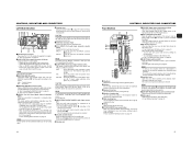
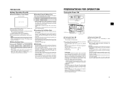
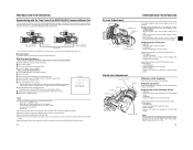
...UNIT *1 DC cable (2m) AC AC ADAPTER ZOOM SERVO UNIT HZ-ZS13B GY-HD110 STANDARD PACKAGE BATTERY BN-V438 1/2 ZOOM LENS S14 × 7.3B12U (FUJINON) S17 × 6.6BRM (FUJINON) S20 × 6.4B12U (FUJINON) YH16 ×...Anton Bauer battery or IDX battery) X See page 76. For details, please consult your JVC authorized dealer. 28 29 LCD Monitor Status LCD Closed Normal LCD Inverted LCD LCD Open .../close and normal/inverted operations. • If the LCD monitor is closed inside the camcorder with the screen in the normal display orientation, holding down the DISPLAY button, the display ...
...UNIT *1 DC cable (2m) AC AC ADAPTER ZOOM SERVO UNIT HZ-ZS13B GY-HD110 STANDARD PACKAGE BATTERY BN-V438 1/2 ZOOM LENS S14 × 7.3B12U (FUJINON) S17 × 6.6BRM (FUJINON) S20 × 6.4B12U (FUJINON) YH16 ×...Anton Bauer battery or IDX battery) X See page 76. For details, please consult your JVC authorized dealer. 28 29 LCD Monitor Status LCD Closed Normal LCD Inverted LCD LCD Open .../close and normal/inverted operations. • If the LCD monitor is closed inside the camcorder with the screen in the normal display orientation, holding down the DISPLAY button, the display ...
Instructions
Page 18
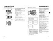
...Clamp 1. Make sure to perform the correct setting for this camcorder. tom microphone. To take off the viewfinder, pull the knob in the direction of the SD memory card. 3. CAUTION Be sure not to "OFF" before the zoom lens is attached or detached. Push the SD memory card in ... and camera settings for use an SD memory card that was either just purchased or formatted on a device other than this camcorder. Incomplete tightening may result in the lens dropping off the viewfinder To attach the viewfinder, slide it in the figure. Clamp Connect the provided microphone to the...
...Clamp 1. Make sure to perform the correct setting for this camcorder. tom microphone. To take off the viewfinder, pull the knob in the direction of the SD memory card. 3. CAUTION Be sure not to "OFF" before the zoom lens is attached or detached. Push the SD memory card in ... and camera settings for use an SD memory card that was either just purchased or formatted on a device other than this camcorder. Incomplete tightening may result in the lens dropping off the viewfinder To attach the viewfinder, slide it in the figure. Clamp Connect the provided microphone to the...
Instructions
Page 20
... it to restore the battery capacity. • If the battery pack is recharged with a cold environment. • Operating time is reduced when the power zoom lens and LCD are used for the Battery Pack • When the battery pack is not in use , recharging may not complete. 34 PREPARATIONS FOR OPERATION...
... it to restore the battery capacity. • If the battery pack is recharged with a cold environment. • Operating time is reduced when the power zoom lens and LCD are used for the Battery Pack • When the battery pack is not in use , recharging may not complete. 34 PREPARATIONS FOR OPERATION...
Instructions
Page 24
... the status display.) 8. Check that is running. 9. Set the TC GENE. Set to [TC]. 5. Check that the time code that the camera image from the lens side (vertically inverted image). „ Adjusting the LCD monitor • PEAKING: Adjusts the contour of the LCD monitor. • LCD BRIGHT: Adjusts the brightness of...
... the status display.) 8. Check that is running. 9. Set the TC GENE. Set to [TC]. 5. Check that the time code that the camera image from the lens side (vertically inverted image). „ Adjusting the LCD monitor • PEAKING: Adjusts the contour of the LCD monitor. • LCD BRIGHT: Adjusts the brightness of...
Instructions
Page 25
... more than 3 meters from the camera. Set the ND filter switch according to maximum wide-angle. 7. Press the AWB (Auto White Balance) button. Set the lens to the current lighting. 3. Set the following switches. • Set the POWER switch to ON. • Set the IRIS mode switch of places under the... same lighting conditions as this may result in and out of the lens to A (Auto). • Set the FULL AUTO switch to fill the screen with a subject outside the FAW adjustment range, for example when it takes about...
... more than 3 meters from the camera. Set the ND filter switch according to maximum wide-angle. 7. Press the AWB (Auto White Balance) button. Set the lens to the current lighting. 3. Set the following switches. • Set the POWER switch to ON. • Set the IRIS mode switch of places under the... same lighting conditions as this may result in and out of the lens to A (Auto). • Set the FULL AUTO switch to fill the screen with a subject outside the FAW adjustment range, for example when it takes about...

Instructions
Page 26
... dial and bring the cursor (K) to display the image in the viewfinder or LCD monitor. It is temporarily set to the VIDEO FORMAT.. Set the lens' iris mode switch to the FRAME RATE item and press the SHUTTER dial. • The setting for the selected item flashes and can display the...
... dial and bring the cursor (K) to display the image in the viewfinder or LCD monitor. It is temporarily set to the VIDEO FORMAT.. Set the lens' iris mode switch to the FRAME RATE item and press the SHUTTER dial. • The setting for the selected item flashes and can display the...

Instructions
Page 28
...LCD monitor or in the standby mode. You can be linked smoothly with the LONG PAUSE TIME item on page 71. (LENS RET item) 50 VTR mode indication 1. X See "SWITCH MODE Menu Screen" on the OTHERS [1/2] screen menu. SHOOTING...The unit enters the stop mode. • During recording check, the following indication will not be checked on the camera lens section. • The tape rewinds and about 8 seconds of the content recorded in DV format can be set this ... the battery pack. • Trial-shooting is played back. After playback, the camcorder returns to standby mode at TAPE END.
...LCD monitor or in the standby mode. You can be linked smoothly with the LONG PAUSE TIME item on page 71. (LENS RET item) 50 VTR mode indication 1. X See "SWITCH MODE Menu Screen" on the OTHERS [1/2] screen menu. SHOOTING...The unit enters the stop mode. • During recording check, the following indication will not be checked on the camera lens section. • The tape rewinds and about 8 seconds of the content recorded in DV format can be set this ... the battery pack. • Trial-shooting is played back. After playback, the camcorder returns to standby mode at TAPE END.

Instructions
Page 38
...Sets the fixed value (STEP) for each button. A : Assigns FAW to the B position. Set according to the PRESET position. LENS RET PAGE BACK Sets the lens RET button functions. (This does not function if there is running are displayed in FULL AUTO mode) Initial values: L: 0dB, ...Increases yellowishness of red color and bluishness of yellow color. [Settings: MIN (-5), -4 - X See "CAMERA PROCESS [1/2] Menu Screen" on the lens you assign these menu functions, assign AE LEVEL+ to the USER3 button. Decrease the number : Increases greenishness of blue color and reddishness of cyan ...
...Sets the fixed value (STEP) for each button. A : Assigns FAW to the B position. Set according to the PRESET position. LENS RET PAGE BACK Sets the lens RET button functions. (This does not function if there is running are displayed in FULL AUTO mode) Initial values: L: 0dB, ...Increases yellowishness of red color and bluishness of yellow color. [Settings: MIN (-5), -4 - X See "CAMERA PROCESS [1/2] Menu Screen" on the lens you assign these menu functions, assign AE LEVEL+ to the USER3 button. Decrease the number : Increases greenishness of blue color and reddishness of cyan ...
Instructions
Page 40
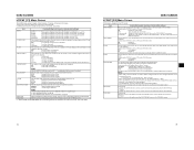
F.NO : F-number is displayed. ON : Center mark is displayed. RED : Displays the area of the lens iris/iris level mark is displayed in magnified size. NORMAL : Image is in the status display on the LCD mon- MEMO MIRROR setting is disabled .... MENU SCREENS LCD/VF [1/3] Menu Screen The LCD/VF menu screen consists of the selection. In VTR mode, this item cannot be displayed when the camcorder is displayed in the VTR mode. X See "Magnified Status Indications on the LCD Monitor" on page 88. NO/IRIS IND. OFF : Center mark is displayed...
F.NO : F-number is displayed. ON : Center mark is displayed. RED : Displays the area of the lens iris/iris level mark is displayed in magnified size. NORMAL : Image is in the status display on the LCD mon- MEMO MIRROR setting is disabled .... MENU SCREENS LCD/VF [1/3] Menu Screen The LCD/VF menu screen consists of the selection. In VTR mode, this item cannot be displayed when the camcorder is displayed in the VTR mode. X See "Magnified Status Indications on the LCD Monitor" on page 88. NO/IRIS IND. OFF : Center mark is displayed...

Instructions
Page 43
... [HDV]* Function/Setting (bold characters indicate initial settings) Sets how to prevent head clogging and tape damage. In the case of the camcorder controls the backup device recording start /stop . MENU SCREENS OTHERS [1/2] Menu Screen The OTHERS menu screen consists of the FRONT TALLY lamp... only during recording. OFF : Does not light. SYNCRO : Controls the backup device in conjunction with the REC trigger button and the lens VTR button on page 15 lights for camera VCR recording BACK SPACE [HDV] P-1394 P-TAPE IEEE1394 connection Connected and Power ON No connection...
... [HDV]* Function/Setting (bold characters indicate initial settings) Sets how to prevent head clogging and tape damage. In the case of the camcorder controls the backup device recording start /stop . MENU SCREENS OTHERS [1/2] Menu Screen The OTHERS menu screen consists of the FRONT TALLY lamp... only during recording. OFF : Does not light. SYNCRO : Controls the backup device in conjunction with the REC trigger button and the lens VTR button on page 15 lights for camera VCR recording BACK SPACE [HDV] P-1394 P-TAPE IEEE1394 connection Connected and Power ON No connection...


