
Product Specification
Page 4
... Power Connectors 86 6.1.1 6.2 Main Power Connector 86 Intel® Riser Card for L SKU 87 6.3 SMBus Connector 87 6.4 Front Panel Connector 87 6.5 I/O Connectors...88 6.5.1 VGA Connector......88 6.5.2 NIC Connectors ...88 6.5.3 SATA Connectors 89 6.5.4 Floppy Controller Connector 89 6.5.5 Serial Port Connectors 90 6.5.6 Keyboard and Mouse Connector 91 6.5.7 USB Connector...91 6.6 Fan Headers ...92 iv Revision 1.8 Intel Order Number: E14960-009 Table of Contents Intel® Server Boards S3200SH...
... Power Connectors 86 6.1.1 6.2 Main Power Connector 86 Intel® Riser Card for L SKU 87 6.3 SMBus Connector 87 6.4 Front Panel Connector 87 6.5 I/O Connectors...88 6.5.1 VGA Connector......88 6.5.2 NIC Connectors ...88 6.5.3 SATA Connectors 89 6.5.4 Floppy Controller Connector 89 6.5.5 Serial Port Connectors 90 6.5.6 Keyboard and Mouse Connector 91 6.5.7 USB Connector...91 6.6 Fan Headers ...92 iv Revision 1.8 Intel Order Number: E14960-009 Table of Contents Intel® Server Boards S3200SH...
Product Specification
Page 5
Hardware Monitoring ...112 9.1 Chassis Intrusion 112 Revision 1.8 v Intel Order Number: E14960-009 Intel® Server Boards S3200SH/S3210SH TPS Table of Conformity (BSMI 107 8.4.6 Korean Compliance (RRL 108 8.5 Mechanical Specifications 109 9. ... 8.4.3 Europe (CE Declaration of Conformity 107 8.4.4 VCCI (Japan) ...107 8.4.5 Taiwan Declaration of Contents 6.7 Miscellaneous Headers and Connectors 92 6.7.1 Back Panel I/O Connectors 92 6.7.2 Chassis Intrusion Header 93 6.7.3 HDD Active LED Header 93 6.7.4 IPMB ...93 6.7.5 HSBP ...93 6.7.6 SATA SGPIO ...94 6.8...
Hardware Monitoring ...112 9.1 Chassis Intrusion 112 Revision 1.8 v Intel Order Number: E14960-009 Intel® Server Boards S3200SH/S3210SH TPS Table of Conformity (BSMI 107 8.4.6 Korean Compliance (RRL 108 8.5 Mechanical Specifications 109 9. ... 8.4.3 Europe (CE Declaration of Conformity 107 8.4.4 VCCI (Japan) ...107 8.4.5 Taiwan Declaration of Contents 6.7 Miscellaneous Headers and Connectors 92 6.7.1 Back Panel I/O Connectors 92 6.7.2 Chassis Intrusion Header 93 6.7.3 HDD Active LED Header 93 6.7.4 IPMB ...93 6.7.5 HSBP ...93 6.7.6 SATA SGPIO ...94 6.8...
Product Specification
Page 8
Pedestal Mount I /O Shield Mechanical Drawing for the Intel® Server Board S3200SH- Output Voltage Timing 99 Figure 38. Pedestal Mount I /O Shield Mechanical Drawing for Intel® Server Boards S3200SH- Intel® Server Board S3210SHLX / S3210SHLC / S3200SHL Back Panel I /O Connectors 93 Figure 37. L/S3210SH-LX ...111 viii Revision 1.8 Intel Order Number: E14960-009 Exit Screen Display 73 Figure 34...
Pedestal Mount I /O Shield Mechanical Drawing for the Intel® Server Board S3200SH- Output Voltage Timing 99 Figure 38. Pedestal Mount I /O Shield Mechanical Drawing for Intel® Server Boards S3200SH- Intel® Server Board S3210SHLX / S3210SHLC / S3200SHL Back Panel I /O Connectors 93 Figure 37. L/S3210SH-LX ...111 viii Revision 1.8 Intel Order Number: E14960-009 Exit Screen Display 73 Figure 34...
Product Specification
Page 10
...J1K2, J7K1, and J4K1J6B2 92 Table 62. Output Voltage Timing 98 x Revision 1.8 Intel Order Number: E14960-009 Setup Utility - Front Panel 24-Pin Header Pin-out (J1K2 87 Table 52. Power Budget ...97 Table 67.... (J1B2) Pin-out 93 Table 63. Network Device Order Fields 70 Table 37. Setup Utility - NIC2-Intel® 82541PI (10/100/1000) Connector Pin-out (J5B1 88 Table 54. External DB9 Serial A Port...92 Table 61. SMBus Connector Pin-out (J1E1 87 Table 51. Setup Utility - Intel® 82566E (10/100/1000) Connector Pin-out (J6B1 89 Table 55. BEV Device Order Fields...
...J1K2, J7K1, and J4K1J6B2 92 Table 62. Output Voltage Timing 98 x Revision 1.8 Intel Order Number: E14960-009 Setup Utility - Front Panel 24-Pin Header Pin-out (J1K2 87 Table 52. Power Budget ...97 Table 67.... (J1B2) Pin-out 93 Table 63. Network Device Order Fields 70 Table 37. Setup Utility - NIC2-Intel® 82541PI (10/100/1000) Connector Pin-out (J5B1 88 Table 54. External DB9 Serial A Port...92 Table 61. SMBus Connector Pin-out (J1E1 87 Table 51. Setup Utility - Intel® 82566E (10/100/1000) Connector Pin-out (J6B1 89 Table 55. BEV Device Order Fields...
Product Specification
Page 15
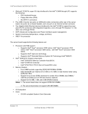
... ƒ System monitoring (temperature, voltage, and fans) ƒ VRD11 for 512 MB, 1 GB, and 2 GB DRAM modules Notes: 1. Intel® Server Boards S3200SH/S3210SH TPS Server Board Overview ƒ Winbond* PC8374L super I/O chip interfaced to the Intel® ICH9R through LPC supports the following feature set: ƒ Processor and FSB support o Supports... at the rear of the server board, two ports via on an internal vertical connector ƒ Two Gigabit (Gbit) Ethernet devices interfaced to the Intel® ICH9R to support two rear panel RJ-45 connectors with integrated magnetics;
... ƒ System monitoring (temperature, voltage, and fans) ƒ VRD11 for 512 MB, 1 GB, and 2 GB DRAM modules Notes: 1. Intel® Server Boards S3200SH/S3210SH TPS Server Board Overview ƒ Winbond* PC8374L super I/O chip interfaced to the Intel® ICH9R through LPC supports the following feature set: ƒ Processor and FSB support o Supports... at the rear of the server board, two ports via on an internal vertical connector ƒ Two Gigabit (Gbit) Ethernet devices interfaced to the Intel® ICH9R to support two rear panel RJ-45 connectors with integrated magnetics;
Product Specification
Page 16
...interface of the ICH ƒ HDD Interface o Six SATA II ports, 300 MB/s ƒ USB o Two USB 2.0 ports connected to the server rear panel o Two USB 2.0 ports connected to headers on the server board o One USB 2.0 port connected to an internal vertical connector ƒ LAN o One Gigabit...SKU: One PCI Express* x16 and one PCI Express* x8 slot, connected to the PCI Express* ports of the MCH; Server Board Overview Intel® Server Boards S3200SH/S3210SH TPS ƒ Video ƒ ServerEngines* Integrated BMC (Baseboard management controller) ƒ External 32 MB (or greater) DDR2 533 MHz ...
...interface of the ICH ƒ HDD Interface o Six SATA II ports, 300 MB/s ƒ USB o Two USB 2.0 ports connected to the server rear panel o Two USB 2.0 ports connected to headers on the server board o One USB 2.0 port connected to an internal vertical connector ƒ LAN o One Gigabit...SKU: One PCI Express* x16 and one PCI Express* x8 slot, connected to the PCI Express* ports of the MCH; Server Board Overview Intel® Server Boards S3200SH/S3210SH TPS ƒ Video ƒ ServerEngines* Integrated BMC (Baseboard management controller) ƒ External 32 MB (or greater) DDR2 533 MHz ...

Product Specification
Page 17
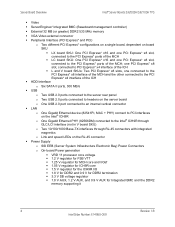
... o One serial port headers o Dual-stacked PS/2 keyboard and mouse connector o USB connectors (two stacked on the rear panel and three on die temperature monitoring through PECI (Platform Environment Control Interface) o Board temperature measurement o Fan speed monitoring and control.../2 keyboard o PS/2 mouse ƒ Power Management Modes Supported (ACPI [Advanced Configuration and Power Interface] Sleep states) o S0 - Intel® Server Boards S3200SH/S3210SH TPS Server Board Overview ƒ System Management o Processor on the server board headers) o SSI-EEB ATX power connectors o One...
... o One serial port headers o Dual-stacked PS/2 keyboard and mouse connector o USB connectors (two stacked on the rear panel and three on die temperature monitoring through PECI (Platform Environment Control Interface) o Board temperature measurement o Fan speed monitoring and control.../2 keyboard o PS/2 mouse ƒ Power Management Modes Supported (ACPI [Advanced Configuration and Power Interface] Sleep states) o S0 - Intel® Server Boards S3200SH/S3210SH TPS Server Board Overview ƒ System Management o Processor on the server board headers) o SSI-EEB ATX power connectors o One...
Product Specification
Page 18
...Self-Test) code indicators during boot ƒ Onboard SATA RAID o Intel® Matrix Storage Technology supports software SATA RAID 0, 1, 10 and 5; Microsoft Windows* driver support only. Server Board Overview Intel® Server Boards S3200SH/S3210SH TPS o One 4-pin SATA RAID Key o One 2-pin ...intrusion detection ƒ BIOS o EFI BIOS ƒ Power Management o Support for SSI interface support ƒ Standard 24-pin SSI front panel, 2x12 main power connector...
...Self-Test) code indicators during boot ƒ Onboard SATA RAID o Intel® Matrix Storage Technology supports software SATA RAID 0, 1, 10 and 5; Microsoft Windows* driver support only. Server Board Overview Intel® Server Boards S3200SH/S3210SH TPS o One 4-pin SATA RAID Key o One 2-pin ...intrusion detection ƒ BIOS o EFI BIOS ƒ Power Management o Support for SSI interface support ƒ Standard 24-pin SSI front panel, 2x12 main power connector...

Product Specification
Page 19
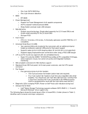
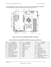
Intel® Server Boards S3200SH/S3210SH TPS A B C D EF GH IJ Server Board Overview K L KK JJ M II HH GG FF EE DD CC BB AA Z Y X W V U T S R Q PO N AF002303 Figure 1. Intel® Server Board S3210SHLX Diagram Table 1. Intel® Server Board S3210SHLX Board SKU Layout Reference Ref ... T SATA 0 U SATA 1 V SGPIO W SATA 2 X SATA 3 Y SATA 4 Z SATA 5 Ref Description AA Password Clear Jumper BB Front Panel Connector CC Chassis Intrusion Jumper DD Floppy Connector EE Internal USB FF External USB GG CMOS Clear Jumper HH BMC Force Update Jumper II BIOS...
Intel® Server Boards S3200SH/S3210SH TPS A B C D EF GH IJ Server Board Overview K L KK JJ M II HH GG FF EE DD CC BB AA Z Y X W V U T S R Q PO N AF002303 Figure 1. Intel® Server Board S3210SHLX Diagram Table 1. Intel® Server Board S3210SHLX Board SKU Layout Reference Ref ... T SATA 0 U SATA 1 V SGPIO W SATA 2 X SATA 3 Y SATA 4 Z SATA 5 Ref Description AA Password Clear Jumper BB Front Panel Connector CC Chassis Intrusion Jumper DD Floppy Connector EE Internal USB FF External USB GG CMOS Clear Jumper HH BMC Force Update Jumper II BIOS...
Product Specification
Page 20
... Connector P Battery Q Main Power Connector R System Fan2 S Floppy Connector T SGPIO U SATA 0 V HSBP W SATA1 X SATA2 Y IPMB Z Front Panel Connector Ref Description AA SATA 4 BB SATA 5 CC SATA 3 DD Internal USB EE External USB FF CMOS Clear Jumper GG Password Clear Jumper HH Recovery...KK Chassis Intrusion LL BMC Force Update Jumper 8 Revision 1.8 Intel Order Number: E14960-009 A letter identifies each connector and major component (shown in Table 2). Server Board Overview Intel® Server Boards S3200SH/S3210SH TPS The following figure shows the board layout of the...
... Connector P Battery Q Main Power Connector R System Fan2 S Floppy Connector T SGPIO U SATA 0 V HSBP W SATA1 X SATA2 Y IPMB Z Front Panel Connector Ref Description AA SATA 4 BB SATA 5 CC SATA 3 DD Internal USB EE External USB FF CMOS Clear Jumper GG Password Clear Jumper HH Recovery...KK Chassis Intrusion LL BMC Force Update Jumper 8 Revision 1.8 Intel Order Number: E14960-009 A letter identifies each connector and major component (shown in Table 2). Server Board Overview Intel® Server Boards S3200SH/S3210SH TPS The following figure shows the board layout of the...
Product Specification
Page 21
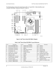
... MHz) Slot 2 C PCI Express* x8 (x4 lane) D PCI Express* x16 (x8 lane) E System Fan 1 Connector F Back Panel Connectors G Diagnostic LEDs H Processor Fan 1 Connector I HH GG J FF EE DD CC BB AA Z Y X WVU T S R Q P O NML K AF002310 Figure 3. Intel® Server Board S3200SH-L/S3200SH-V SKU Diagram Table3. A letter identifies each connector and major component (shown in Table 3).
... MHz) Slot 2 C PCI Express* x8 (x4 lane) D PCI Express* x16 (x8 lane) E System Fan 1 Connector F Back Panel Connectors G Diagnostic LEDs H Processor Fan 1 Connector I HH GG J FF EE DD CC BB AA Z Y X WVU T S R Q P O NML K AF002310 Figure 3. Intel® Server Board S3200SH-L/S3200SH-V SKU Diagram Table3. A letter identifies each connector and major component (shown in Table 3).

Product Specification
Page 37
... provides two external USB ports on the rear panel of the server board. The Universal Serial Bus Specification, Revision 1.1 defines the external connectors. It implements ACPI-compliant power management features. Revision 1.8 25 Intel Order Number: E14960-009 The PCI Express* interface... chipset; All ports function identically and with the capability to four USB connectors. Intel® Server Boards S3200SH/S3210SH TPS Functional Architecture 3.2.3.17 PCI Express* x4 Sub-system The Intel® ICH9R supports one PCI Express* x4-lane interface that support data transfer...
... provides two external USB ports on the rear panel of the server board. The Universal Serial Bus Specification, Revision 1.1 defines the external connectors. It implements ACPI-compliant power management features. Revision 1.8 25 Intel Order Number: E14960-009 The PCI Express* interface... chipset; All ports function identically and with the capability to four USB connectors. Intel® Server Boards S3200SH/S3210SH TPS Functional Architecture 3.2.3.17 PCI Express* x4 Sub-system The Intel® ICH9R supports one PCI Express* x4-lane interface that support data transfer...

Product Specification
Page 72
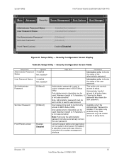
Intel® Server Boards S3200SH/S3210SH TPS Advanced PCI Configuration Dual Monitor Video Onboard NIC ROM NIC 1 MAC Address NIC 2 MAC Address Enabled / Disabled Enabled / Disabled System BIOS Figure 20. ... the MAC address. 4.3.2.3 Security Screen The Security screen provides fields to enable and set the user and administrative password and to lock out the front panel buttons so they cannot be enabled for the onboard network controllers. To access this screen from the Main screen, select the Security option. 60 Revision...
Intel® Server Boards S3200SH/S3210SH TPS Advanced PCI Configuration Dual Monitor Video Onboard NIC ROM NIC 1 MAC Address NIC 2 MAC Address Enabled / Disabled Enabled / Disabled System BIOS Figure 20. ... the MAC address. 4.3.2.3 Security Screen The Security screen provides fields to enable and set the user and administrative password and to lock out the front panel buttons so they cannot be enabled for the onboard network controllers. To access this screen from the Main screen, select the Security option. 60 Revision...
Product Specification
Page 73
... Item Administrator Password Status Options User Password Status Set Administrator Password [123abcd] Set User Password [123abcd] Front Panel Lockout Enabled Disabled Help Text Administrator password is used . Only alphanumeric characters can be used to control change ...is installed. Available only if the Administrator Password is 7 characters. This option only protects setup. System BIOS Intel® Server Boards S3200SH/S3210SH TPS Main Advanced Security Server Management Boot Options Boot Manager Administrator Password Status User Password Status Set Administrator ...
... Item Administrator Password Status Options User Password Status Set Administrator Password [123abcd] Set User Password [123abcd] Front Panel Lockout Enabled Disabled Help Text Administrator password is used . Only alphanumeric characters can be used to control change ...is installed. Available only if the Administrator Password is 7 characters. This option only protects setup. System BIOS Intel® Server Boards S3200SH/S3210SH TPS Main Advanced Security Server Management Boot Options Boot Manager Administrator Password Status User Password Status Set Administrator ...

Product Specification
Page 99
... the riser card is provided to be populated with PCI Express* x16 slot on the Intel® Server Board S3200SH-L. The following table details the pin-out of this header. Front Panel 24-Pin Header Pin-out (J1K2) Signal Name FP_PWR_LED_P1 Pin Signal Name Pin 1 P3V3_STBY... Clock Line Test Point 6.4 Front Panel Connector A standard SSI 24-pin header is PCI Express* x8. Connectors and Jumper Blocks Intel® Server Boards S3200SH/S3210SH TPS 6.2 Intel® Riser Card for populating the Intel® Server Board S3200SH-L into the Intel® Server Chassis SR1530. 6.3 SMBus...
... the riser card is provided to be populated with PCI Express* x16 slot on the Intel® Server Board S3200SH-L. The following table details the pin-out of this header. Front Panel 24-Pin Header Pin-out (J1K2) Signal Name FP_PWR_LED_P1 Pin Signal Name Pin 1 P3V3_STBY... Clock Line Test Point 6.4 Front Panel Connector A standard SSI 24-pin header is PCI Express* x8. Connectors and Jumper Blocks Intel® Server Boards S3200SH/S3210SH TPS 6.2 Intel® Riser Card for populating the Intel® Server Board S3200SH-L into the Intel® Server Chassis SR1530. 6.3 SMBus...

Product Specification
Page 104
..., J4J1, J6B1, and J6J1) and have the same pin-out. Fan Speed Control signal 6.7 Miscellaneous Headers and Connectors 6.7.1 Back Panel I /O Connectors 92 Revision 1.8 Intel Order Number: E14960-009 Four-pin Fan Headers Pin-out (J4D1, J1K2, J7K1, and J4K1J6B2) Pin Signal Name 1 Ground 2... to the Heceta* to support two additional USB connectors. Pulse Width Modulation - Intel® Server Board S3210SHLX / S3210SHLC / S3200SHL Back Panel I /O Connectors Figure 35. Intel® Server Boards S3200SH/S3210SH TPS Connectors and Jumper Blocks A header on the server board provides an ...
..., J4J1, J6B1, and J6J1) and have the same pin-out. Fan Speed Control signal 6.7 Miscellaneous Headers and Connectors 6.7.1 Back Panel I /O Connectors 92 Revision 1.8 Intel Order Number: E14960-009 Four-pin Fan Headers Pin-out (J4D1, J1K2, J7K1, and J4K1J6B2) Pin Signal Name 1 Ground 2... to the Heceta* to support two additional USB connectors. Pulse Width Modulation - Intel® Server Board S3210SHLX / S3210SHLC / S3200SHL Back Panel I /O Connectors Figure 35. Intel® Server Boards S3200SH/S3210SH TPS Connectors and Jumper Blocks A header on the server board provides an ...

Product Specification
Page 105
...Pin 1 2 Signal Name FM_SIO_SCSI_ACT_N TP_SCSI_ACT_PIN2 6.7.4 IPMB There is a 4-pin HSBP connector jumper. Revision 1.8 93 Intel Order Number: E14960-009 Intel® Server Board S3200SHV Back Panel I/O Connectors 6.7.2 Chassis Intrusion Header A 1x2 pin header (J1B2) is used in chassis that support the SCSI ... hot-swap backplane. This jumper is reserved for HDD LED connection. Table 63. Connectors and Jumper Blocks Keyboard Intel® Server Boards S3200SH/S3210SH TPS Serial A LAN Mouse VGA POST Code LED USB Figure 36. This jumper is reserved for this ...
...Pin 1 2 Signal Name FM_SIO_SCSI_ACT_N TP_SCSI_ACT_PIN2 6.7.4 IPMB There is a 4-pin HSBP connector jumper. Revision 1.8 93 Intel Order Number: E14960-009 Intel® Server Board S3200SHV Back Panel I/O Connectors 6.7.2 Chassis Intrusion Header A 1x2 pin header (J1B2) is used in chassis that support the SCSI ... hot-swap backplane. This jumper is reserved for HDD LED connection. Table 63. Connectors and Jumper Blocks Keyboard Intel® Server Boards S3200SH/S3210SH TPS Serial A LAN Mouse VGA POST Code LED USB Figure 36. This jumper is reserved for this ...

Software User's Guide
Page 5
... Up a RAID Array Using the Configuration Wizard 70 Creating RAID 0, 1, 5, or 6 using Intel® RAID BIOS Console 2 (detailed 73 Creating RAID 10, RAID 50, and RAID 60 using Intel® RAID BIOS Console 2 77 Setting Drive Parameters ...82 Creating a Hot Spare ...83 Viewing...92 Uninstalling Intel® RAID Web Console 2 for VMWare 92 Installing Intel® RAID Web Console 2 Support on the VMWare ESX 93 Starting the Intel® RAID Web Console 2 98 Intel® RAID Web Console 2 Screens 98 Physical/Virtual View Panel 101 Properties/Operations/Graphical View Panel 102 Intel®...
... Up a RAID Array Using the Configuration Wizard 70 Creating RAID 0, 1, 5, or 6 using Intel® RAID BIOS Console 2 (detailed 73 Creating RAID 10, RAID 50, and RAID 60 using Intel® RAID BIOS Console 2 77 Setting Drive Parameters ...82 Creating a Hot Spare ...83 Viewing...92 Uninstalling Intel® RAID Web Console 2 for VMWare 92 Installing Intel® RAID Web Console 2 Support on the VMWare ESX 93 Starting the Intel® RAID Web Console 2 98 Intel® RAID Web Console 2 Screens 98 Physical/Virtual View Panel 101 Properties/Operations/Graphical View Panel 102 Intel®...

Software User's Guide
Page 6
Event Log Panel ...103 Menu Bar/Manage Menu 104 Menu Bar/Go To Menu 104 File Menu/Log Menu 104 File Menu/Tool Menu 104 File Menu/Help ... 144 Enabling Full Disk Encryption feature 144 Enabling Snapshot feature 153 Enabling Super Sized Cache 163 Appendix A: Creating a Virtual Drive Using Advanced Configuration 167 vi Intel® RAID Software User's Guide
Event Log Panel ...103 Menu Bar/Manage Menu 104 Menu Bar/Go To Menu 104 File Menu/Log Menu 104 File Menu/Tool Menu 104 File Menu/Help ... 144 Enabling Full Disk Encryption feature 144 Enabling Snapshot feature 153 Enabling Super Sized Cache 163 Appendix A: Creating a Virtual Drive Using Advanced Configuration 167 vi Intel® RAID Software User's Guide

Software User's Guide
Page 88
...; RAID Software User's Guide For information about setting these parameters, see "Setting Drive Parameters" on right panel of the configuration. 12. Intel® RAID BIOS Console 2 - Click Accept to save the configuration, or click Back to return to the previous screens and ... from the first dropdown box. 9. Depending on the RAID level you choose , you may need to the previous settings. Set Array Properties 11. The Intel® RAID BIOS Console 2 configuration utility displays a preview of the screen for some RAID levels are listed on page 82. This example shows a specific ...
...; RAID Software User's Guide For information about setting these parameters, see "Setting Drive Parameters" on right panel of the configuration. 12. Intel® RAID BIOS Console 2 - Click Accept to save the configuration, or click Back to return to the previous screens and ... from the first dropdown box. 9. Depending on the RAID level you choose , you may need to the previous settings. Set Array Properties 11. The Intel® RAID BIOS Console 2 configuration utility displays a preview of the screen for some RAID levels are listed on page 82. This example shows a specific ...