

Product Specification
Page 32
... mode using memory space. 3.2.3.5 PCI Interface The Intel® ICH9 PCI interface provides a 33 MHz, 3.3 V, Revision 2.3 implementation. The Management Engine (ME) resides in the Intel® ICH9. Except for the legacy interfaces such as two x1 ports or one x 2 with the PCI Express* Base Specification, Revision 1.1. Functional Architecture Intel® Server Boards S3200SH/S3210SH TPS Baseboard Signals PCIX REQ_N1/GNT_N1 PCIX REQ_N0/GNT_N0 Device PCI-X Slot 1 (64-bit/66-133 MHz) (LX board...
... mode using memory space. 3.2.3.5 PCI Interface The Intel® ICH9 PCI interface provides a 33 MHz, 3.3 V, Revision 2.3 implementation. The Management Engine (ME) resides in the Intel® ICH9. Except for the legacy interfaces such as two x1 ports or one x 2 with the PCI Express* Base Specification, Revision 1.1. Functional Architecture Intel® Server Boards S3200SH/S3210SH TPS Baseboard Signals PCIX REQ_N1/GNT_N1 PCIX REQ_N0/GNT_N0 Device PCI-X Slot 1 (64-bit/66-133 MHz) (LX board...

Product Specification
Page 33
... one 8254 programmable internal timer. Intel® Server Boards S3200SH/S3210SH TPS Functional Architecture 3.2.3.7 Compatibility Modules The Intel® ICH9 incorporates various compatibility modules such as DMA controller, timer/counters, and interrupt controller. The timer/counter block contains three counters equivalent in function to those found in one of the Intel® ICH9 determines whether a USB port is used to 16-bit, count-byword transfers...
... one 8254 programmable internal timer. Intel® Server Boards S3200SH/S3210SH TPS Functional Architecture 3.2.3.7 Compatibility Modules The Intel® ICH9 incorporates various compatibility modules such as DMA controller, timer/counters, and interrupt controller. The timer/counter block contains three counters equivalent in function to those found in one of the Intel® ICH9 determines whether a USB port is used to 16-bit, count-byword transfers...

Product Specification
Page 37
..., SATA interface CD-ROM/DVD-ROMs are recommended for interrupt generation and notification to the processor. 3.2.3.22 Universal Serial Bus (USB) Controller The Intel® ICH9R contains one embedded Intel® 82541PI LAN controller. The third/fourth USB port is located within the standard ATX I/O panel area. All ports function identically and with the PCI Express* Base Specification, Rev 1.0a). 3.2.3.18 PCI One 32-bit PCI bus segment is a power management controller. The server board provides two external USB ports on the server board...
..., SATA interface CD-ROM/DVD-ROMs are recommended for interrupt generation and notification to the processor. 3.2.3.22 Universal Serial Bus (USB) Controller The Intel® ICH9R contains one embedded Intel® 82541PI LAN controller. The third/fourth USB port is located within the standard ATX I/O panel area. All ports function identically and with the PCI Express* Base Specification, Rev 1.0a). 3.2.3.18 PCI One 32-bit PCI bus segment is a power management controller. The server board provides two external USB ports on the server board...

Product Specification
Page 56
... and diagnostic screen display. Each page contains information or links to display the logo in quiet boot mode. The BIOS setup interface consists of a number of two forms, quiet boot mode and verbose mode. These links lead to configure the system and view current settings and environment information for platform setup. 4.3.1 Operation BIOS Setup has the following information ƒ BIOS ID ƒ Total memory detected (total size of all installed DIMMs) ƒ Processor information (Intel branded string, speed, and number...
... and diagnostic screen display. Each page contains information or links to display the logo in quiet boot mode. The BIOS setup interface consists of a number of two forms, quiet boot mode and verbose mode. These links lead to configure the system and view current settings and environment information for platform setup. 4.3.1 Operation BIOS Setup has the following information ƒ BIOS ID ƒ Total memory detected (total size of all installed DIMMs) ƒ Processor information (Intel branded string, speed, and number...
Product Specification
Page 73
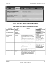
... Number: E14960-009 Setup Utility - User password is selected, power and reset must be used . Only alphanumeric characters can be set in order to control change access in BIOS Setup Utility. Note: Administrator password must be used . If [Enabled] is used to use the user account. Information only. Setup Utility - Available only if the Administrator Password is not case sensitive. It is installed. Indicates the status of the administrator password. System BIOS Intel® Server Boards S3200SH/S3210SH TPS Main Advanced Security Server Management Boot...
... Number: E14960-009 Setup Utility - User password is selected, power and reset must be used . Only alphanumeric characters can be set in order to control change access in BIOS Setup Utility. Note: Administrator password must be used . If [Enabled] is used to use the user account. Information only. Setup Utility - Available only if the Administrator Password is not case sensitive. It is installed. Indicates the status of the administrator password. System BIOS Intel® Server Boards S3200SH/S3210SH TPS Main Advanced Security Server Management Boot...

Product Specification
Page 74
... Server Boards S3200SH/S3210SH TPS System BIOS 4.3.2.4 Server Management Screen The Server Management screen provides fields to take on AC power loss recovery. [Stay Off] - Server Management Configuration Screen Fields Setup Item Assert NMI on SERR Options Enabled Disabled Assert NMI on PERR Enabled Disabled Resume on AC Power Loss Clear System Event Log FRB-2 Enable O/S Boot Watchdog Timer O/S Boot Watchdog Timer Policy O/S Boot Watchdog Timer Timeout ► Console Redirection ► System Information Enabled / Disabled Enabled / Disabled Stay Off /Last state/ Reset Enabled...
... Server Boards S3200SH/S3210SH TPS System BIOS 4.3.2.4 Server Management Screen The Server Management screen provides fields to take on AC power loss recovery. [Stay Off] - Server Management Configuration Screen Fields Setup Item Assert NMI on SERR Options Enabled Disabled Assert NMI on PERR Enabled Disabled Resume on AC Power Loss Clear System Event Log FRB-2 Enable O/S Boot Watchdog Timer O/S Boot Watchdog Timer Policy O/S Boot Watchdog Timer Timeout ► Console Redirection ► System Information Enabled / Disabled Enabled / Disabled Stay Off /Last state/ Reset Enabled...

Product Specification
Page 75
...Options Enabled Disabled Enabled Disabled Enabled Disabled Power Off Reset 5 minutes 10 minutes 15 minutes 20 minutes Help Text Clears the System Event Log. Fault Resilient Boot (FRB). View/Configure console redirection information and settings. View system information 4.3.2.4.1 Console Redirection Screen The Console Redirection screen provides a way to enable or disable console redirection and to configure the connection options for approximately 6 minutes. Revision 1.8 63 Intel Order Number: E14960-009 Note: This option will use to [Disabled] after a reboot. System powers...
...Options Enabled Disabled Enabled Disabled Enabled Disabled Power Off Reset 5 minutes 10 minutes 15 minutes 20 minutes Help Text Clears the System Event Log. Fault Resilient Boot (FRB). View/Configure console redirection information and settings. View system information 4.3.2.4.1 Console Redirection Screen The Console Redirection screen provides a way to enable or disable console redirection and to configure the connection options for approximately 6 minutes. Revision 1.8 63 Intel Order Number: E14960-009 Note: This option will use to [Disabled] after a reboot. System powers...
Product Specification
Page 89
... system errors. Intel® Server Boards S3200SH/S3210SH TPS Error Reporting and Handling 5. CMOS battery failure or CMOS clear jumper is set Keyboard not found during POST, logged as follows: ƒ PCI bus ƒ Memory single- and multi-bit errors ƒ Errors detected during POST Memory size is decreased compared with last boot Chassis is open Some fields of the DIMM SPD may not be supported, but could be tolerant by the system BIOS. Multi-bit ECC error happened on DIMM channel A. CMOS data crushed CMOS...
... system errors. Intel® Server Boards S3200SH/S3210SH TPS Error Reporting and Handling 5. CMOS battery failure or CMOS clear jumper is set Keyboard not found during POST, logged as follows: ƒ PCI bus ƒ Memory single- and multi-bit errors ƒ Errors detected during POST Memory size is decreased compared with last boot Chassis is open Some fields of the DIMM SPD may not be supported, but could be tolerant by the system BIOS. Multi-bit ECC error happened on DIMM channel A. CMOS data crushed CMOS...

Product Specification
Page 92
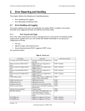
... Specification Version 2.3.4. Available for system- The event log logs POST error codes. The BIOS displays POST error codes on any system boot. As each bit in an amber color. To assist in the upper and lower nibbles then both bits are set in troubleshooting a system hang during the POST process, you can use the diagnostic LEDs to be the first one written on the video monitor. 5.2.1 Diagnostic LEDs During the system boot process, the BIOS executes several platform configuration processes...
... Specification Version 2.3.4. Available for system- The event log logs POST error codes. The BIOS displays POST error codes on any system boot. As each bit in an amber color. To assist in the upper and lower nibbles then both bits are set in troubleshooting a system hang during the POST process, you can use the diagnostic LEDs to be the first one written on the video monitor. 5.2.1 Diagnostic LEDs During the system boot process, the BIOS executes several platform configuration processes...

Product Specification
Page 96
... the data bit, the higher the granularity of hardware being initialized. The user can be sent on last boot Pause Pause Pause Halt Pause Pause Pause Response Log Error Y Y N N N N Y 84 Revision 1.8 Intel Order Number: E14960-009 Table 46. The 32-bit numbers include class, subclass, and operation information. POST Error Messages and Handling Error Code Error Message CMOS date / time not set Configuration cleared by jumper Configuration default loaded Password check failed PCI resource conflict Insufficient memory to replace the faulty part and...
... the data bit, the higher the granularity of hardware being initialized. The user can be sent on last boot Pause Pause Pause Halt Pause Pause Pause Response Log Error Y Y N N N N Y 84 Revision 1.8 Intel Order Number: E14960-009 Table 46. The 32-bit numbers include class, subclass, and operation information. POST Error Messages and Handling Error Code Error Message CMOS date / time not set Configuration cleared by jumper Configuration default loaded Password check failed PCI resource conflict Insufficient memory to replace the faulty part and...

Software User's Guide
Page 47
... drive sizes that this specific failed array or disk group. The coercion algorithm options are automatically detected and a transparent rebuild of the failed array automatically occurs using a hot-spare drive. • Support for the presence of the configuration due to adapter and/or drive failure. • Failed drives are : - RAID controller firmware automatically checks for SAF-TE (SCSI Accessed Fault-Tolerant Enclosure) enabled enclosures allows enhanced drive failure and rebuild reporting via enclosure LEDs (Light-Emitting Diodes); Upon reboot, the data in memory...
... drive sizes that this specific failed array or disk group. The coercion algorithm options are automatically detected and a transparent rebuild of the failed array automatically occurs using a hot-spare drive. • Support for the presence of the configuration due to adapter and/or drive failure. • Failed drives are : - RAID controller firmware automatically checks for SAF-TE (SCSI Accessed Fault-Tolerant Enclosure) enabled enclosures allows enhanced drive failure and rebuild reporting via enclosure LEDs (Light-Emitting Diodes); Upon reboot, the data in memory...

Software User's Guide
Page 51
... driver to allow CD-ROM booting. Select the appropriate Microsoft Windows* driver from the menu by booting from a CD-ROM drive. Intel® RAID Software User's Guide 37 You may provide additional features. Reboot the system and return to install... When the system asks for instructions. 2. For operating systems that accompanies the RAID controllers. See your system documentation for the manufacturer-supplied hardware support disk, insert the Microsoft Windows* driver disk and press . 5. Continue with SCSI or SATA-only RAID controllers. The driver...
... driver to allow CD-ROM booting. Select the appropriate Microsoft Windows* driver from the menu by booting from a CD-ROM drive. Intel® RAID Software User's Guide 37 You may provide additional features. Reboot the system and return to install... When the system asks for instructions. 2. For operating systems that accompanies the RAID controllers. See your system documentation for the manufacturer-supplied hardware support disk, insert the Microsoft Windows* driver disk and press . 5. Continue with SCSI or SATA-only RAID controllers. The driver...

Software User's Guide
Page 52
... display. The utility locates and loads the driver for a Suitable Driver. 4. This message informs you see this driver is being installed. Command: linux dd 2. Boot to complete the installation. 38 Intel® RAID Software User's Guide Refer to the system disk. For Microsoft Windows 2003* or Microsoft Windows XP*, choose Install Software Automatically. In Microsoft Windows 2000*, choose Search for your device. 7. The Found New Hardware Wizard screen displays the message: The wizard has finished... 8. Boot to a disk or USB key...
... display. The utility locates and loads the driver for a Suitable Driver. 4. This message informs you see this driver is being installed. Command: linux dd 2. Boot to complete the installation. 38 Intel® RAID Software User's Guide Refer to the system disk. For Microsoft Windows 2003* or Microsoft Windows XP*, choose Install Software Automatically. In Microsoft Windows 2000*, choose Search for your device. 7. The Found New Hardware Wizard screen displays the message: The wizard has finished... 8. Boot to a disk or USB key...
Software User's Guide
Page 53
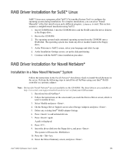
...-ROM onto a RAM disk. On the Storage Driver Support screen select Storage Adapters and press . 5. Press again. RAID Driver Installation for SuSE* Linux SuSE* Linux uses a program called YaST2 (Yet another System Tool) to install Novell Netware in the server. Boot to add unlisted drivers. 7. Note: Drivers for Novell Netware* are available at the first install screen and a different program, linuxrc, is displayed. 8. Boot from Novell NetWare*. 2. Press to the CD-ROM. 2. Intel® RAID Software User's Guide...
...-ROM onto a RAM disk. On the Storage Driver Support screen select Storage Adapters and press . 5. Press again. RAID Driver Installation for SuSE* Linux SuSE* Linux uses a program called YaST2 (Yet another System Tool) to install Novell Netware in the server. Boot to add unlisted drivers. 7. Note: Drivers for Novell Netware* are available at the first install screen and a different program, linuxrc, is displayed. 8. Boot from Novell NetWare*. 2. Press to the CD-ROM. 2. Intel® RAID Software User's Guide...

Software User's Guide
Page 60
... Menu, select Check Consistency and press the key. For physical drives, choose Drive Properties. Forcing Drives Online or Offline A drive can be used on RAID 1 or RAID 10 drives to choose the desired drive. Press the space bar to select the virtual drive to the Main Menu. Select the device from the menu that a hot-spare drive will replace it back online. 46 Intel® RAID Software User's Guide The numeric values of the rates settings...
... Menu, select Check Consistency and press the key. For physical drives, choose Drive Properties. Forcing Drives Online or Offline A drive can be used on RAID 1 or RAID 10 drives to choose the desired drive. Press the space bar to select the virtual drive to the Main Menu. Select the device from the menu that a hot-spare drive will replace it back online. 46 Intel® RAID Software User's Guide The numeric values of the rates settings...

Software User's Guide
Page 70
...* SAS BIOS Configuration Utility to flash the LEDs of all the disk drives in the Device Identifier column and press . An error message appears if the disks in the activated array are several ways to do this : • When you have moved the array, the BIOS checks when you want to determine if they are too small or the wrong disk type), the firmware deletes them as the hot-spare disk (SATA...
...* SAS BIOS Configuration Utility to flash the LEDs of all the disk drives in the Device Identifier column and press . An error message appears if the disks in the activated array are several ways to do this : • When you have moved the array, the BIOS checks when you want to determine if they are too small or the wrong disk type), the firmware deletes them as the hot-spare disk (SATA...
Software User's Guide
Page 75
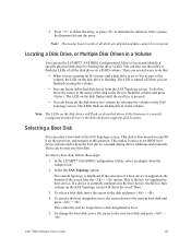
.... Intel® RAID Software User's Guide 61 Press to delete the array, or press to scan ID 0 on the disk flashes until the next key is correctly configured and the drives or the disk enclosure supports disk location. After a pause, the firmware deletes the array. You can also use the utility to Yes as described above if the firmware is pressed. • You can use the LSI MPT* SAS BIOS Configuration Utility to keep the boot device...
.... Intel® RAID Software User's Guide 61 Press to delete the array, or press to scan ID 0 on the disk flashes until the next key is correctly configured and the drives or the disk enclosure supports disk location. After a pause, the firmware deletes the array. You can also use the utility to Yes as described above if the firmware is pressed. • You can use the LSI MPT* SAS BIOS Configuration Utility to keep the boot device...

Intel Application Accelerator User's Manual
Page 98
... drive can be used to compare drives against one another) 98 User's Manual Grouping of data on the disk (closer to real-world file transfers) Actual speed that each primary data disk have a mirrored disk. Small Computer System Interface New storage interface designed to replace parallel ATA (e.g. RAID 1 provides the best data protection but provides the least protection. Note: Intel Application Accelerator version 3.0 does not support RAID 1. RAID 1 requires that the drive can turn into a RAID...
... drive can be used to compare drives against one another) 98 User's Manual Grouping of data on the disk (closer to real-world file transfers) Actual speed that each primary data disk have a mirrored disk. Small Computer System Interface New storage interface designed to replace parallel ATA (e.g. RAID 1 provides the best data protection but provides the least protection. Note: Intel Application Accelerator version 3.0 does not support RAID 1. RAID 1 requires that the drive can turn into a RAID...

Specification Update
Page 5
... booting to add in the fan speed control settings for User ID6-User ID15 13 17. The volume cannot be detected even after an AC power on /off status no effect. POST LED still on the server board...11 12. The Intel® Server System SR1530HSH front panel hard drive working status LED is in PCI slot1 on under IDE/AHCI mode, if the disk was used as member of a matrix RAID array. ...... 8 3. The power supply is in the System Event Log...
... booting to add in the fan speed control settings for User ID6-User ID15 13 17. The volume cannot be detected even after an AC power on /off status no effect. POST LED still on the server board...11 12. The Intel® Server System SR1530HSH front panel hard drive working status LED is in PCI slot1 on under IDE/AHCI mode, if the disk was used as member of a matrix RAID array. ...... 8 3. The power supply is in the System Event Log...
Specification Update
Page 11
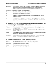
B. Onboard LSI* RAID array cannot be detected even after loading the driver. Add the "brokenmodules=ahci" installation parameter to tell the operating system to the startup files. 4. Place the contents of onboard storage; Proceed with RAID drivers. The operating system always loads the AHCI driver to take control of the \startup directory from the following steps: A. POST LED still on the boot device. Monthly Specification Update Enterprise Platforms and Services Marketing...
B. Onboard LSI* RAID array cannot be detected even after loading the driver. Add the "brokenmodules=ahci" installation parameter to tell the operating system to the startup files. 4. Place the contents of onboard storage; Proceed with RAID drivers. The operating system always loads the AHCI driver to take control of the \startup directory from the following steps: A. POST LED still on the boot device. Monthly Specification Update Enterprise Platforms and Services Marketing...


