
Service Guide
Page 5
... device drivers and software to manage your system components and their supported accessories, refer to add and replace components on the Intel® Server System R1000RP family products. Chapter 2 provides instructions on using the utilities that may need, troubleshooting information, and... or any of this chapter for step-bystep instructions and diagrams for navigating through the BIOS Setup screens, performing a BIOS update, and resetting the password or BIOS defaults. Product Safety and Regulatory Compliance Document Intel® Server System R1000RP Service Guide v
... device drivers and software to manage your system components and their supported accessories, refer to add and replace components on the Intel® Server System R1000RP family products. Chapter 2 provides instructions on using the utilities that may need, troubleshooting information, and... or any of this chapter for step-bystep instructions and diagrams for navigating through the BIOS Setup screens, performing a BIOS update, and resetting the password or BIOS defaults. Product Safety and Regulatory Compliance Document Intel® Server System R1000RP Service Guide v
Service Guide
Page 7
... a Slimline Optical Drive 47 Installing and Removing Intel® I/O Expansion Module 48 Installing Intel® I/O Expansion Module 48 Removing Intel® I/O Expansion Module 48 Installing and Removing the Intel® ESRTII SATA Key 49 Installing the Intel® ESRTII SATA Key 49 Removing the Intel® ESRTII SATA Key 49 Installing and Removing...61 Installing and Removing the Rack Handles 62 Installing the Rack Handles 62 Removing the Rack Handles 62 3 Server Utilities 63 Using the BIOS Setup Utility 63 Starting Setup ...63 Intel® Server System R1000RP Service Guide vii
... a Slimline Optical Drive 47 Installing and Removing Intel® I/O Expansion Module 48 Installing Intel® I/O Expansion Module 48 Removing Intel® I/O Expansion Module 48 Installing and Removing the Intel® ESRTII SATA Key 49 Installing the Intel® ESRTII SATA Key 49 Removing the Intel® ESRTII SATA Key 49 Installing and Removing...61 Installing and Removing the Rack Handles 62 Installing the Rack Handles 62 Removing the Rack Handles 62 3 Server Utilities 63 Using the BIOS Setup Utility 63 Starting Setup ...63 Intel® Server System R1000RP Service Guide vii
Service Guide
Page 8
Table of Contents Setup Navigation Keyboard Commands 63 Setup Screen Menu Selection Bar 64 BIOS Setup Utility Screens 64 Map of Screens and Functionality 65 Main Screen (Tab)...67 Advanced Screen (Tab 70 Processor Configuration 72 Memory Configuration 80 Mass ... A: Technical Reference 147 System Environmental Specifications 147 Appendix B: Regulatory and Compliance Information 149 Appendix C: LED Decoder 150 Appendix D: Getting Help 154 Warranty Information 154 Appendix E: Intel® Server Issue Report Form 155 viii Intel® Server System R1000RP Service Guide
Table of Contents Setup Navigation Keyboard Commands 63 Setup Screen Menu Selection Bar 64 BIOS Setup Utility Screens 64 Map of Screens and Functionality 65 Main Screen (Tab)...67 Advanced Screen (Tab 70 Processor Configuration 72 Memory Configuration 80 Mass ... A: Technical Reference 147 System Environmental Specifications 147 Appendix B: Regulatory and Compliance Information 149 Appendix C: LED Decoder 150 Appendix D: Getting Help 154 Warranty Information 154 Appendix E: Intel® Server Issue Report Form 155 viii Intel® Server System R1000RP Service Guide
Service Guide
Page 12
...; Server System R1000RP Feature Summary 2 Table 4. Server System References...v Table 2. POST Progress Code Decoder 151 xii Intel® Server System R1000RP Service Guide System Environmental Limits Summary 147 Table 10. BMC Boot/Reset Status LED Indicators 13 Table 6. Server Board... Jumpers ...14 Table 7. System Status LED State Definitions 11 Table 5. Screen Map ...65 Table 9. BIOS Setup: Keyboard Command Bar 63 Table 8. List of Tables List of Tables Table 1. POST Progress Code LED Example 150 Table 11.
...; Server System R1000RP Feature Summary 2 Table 4. Server System References...v Table 2. POST Progress Code Decoder 151 xii Intel® Server System R1000RP Service Guide System Environmental Limits Summary 147 Table 10. BMC Boot/Reset Status LED Indicators 13 Table 6. Server Board... Jumpers ...14 Table 7. System Status LED State Definitions 11 Table 5. Screen Map ...65 Table 9. BIOS Setup: Keyboard Command Bar 63 Table 8. List of Tables List of Tables Table 1. POST Progress Code LED Example 150 Table 11.
Service Guide
Page 25
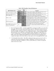
...while it pulls the Linux* image into flash. Post Code Diagnostic LEDs - The purpose of these LEDs are located on replacing this motherboard. Intel® Server System R1000RP Service Guide 13 Server will be in troubleshooting a system hang condition during the POST process. Fault/Status LEDs operate ...as a service caution indicator to assist in this state for information on replacing this motherboard. During the system boot process, the BIOS executes a number of BMC boot/reset process. The diagnostic LEDs can be used to identify the last POST process to be in u-Boot...
...while it pulls the Linux* image into flash. Post Code Diagnostic LEDs - The purpose of these LEDs are located on replacing this motherboard. Intel® Server System R1000RP Service Guide 13 Server will be in troubleshooting a system hang condition during the POST process. Fault/Status LEDs operate ...as a service caution indicator to assist in this state for information on replacing this motherboard. During the system boot process, the BIOS executes a number of BMC boot/reset process. The diagnostic LEDs can be used to identify the last POST process to be in u-Boot...

Service Guide
Page 26
Disabled (Default) 2-3 ME Firmware Force Update Mode - Enabled 14 Intel® Server System R1000RP Service Guide Table 6. Server Board Jumpers Jumper Name J3K6: BMC Force Update J2K8: BIOS Recovery J2K6: BIOS Default J3K2: ME Force Update Pins System Results 1-2 BMC Firmware Force Update Mode - For ...before removing any system components or moving any of the on http://www.intel.com/support/. Enabled 1-2 Pins 1-2 should have a jumper in place for normal system operation. (Default) 2-3 The main system BIOS does not boot with AC power plugged in, the CMOS settings clear in...
Disabled (Default) 2-3 ME Firmware Force Update Mode - Enabled 14 Intel® Server System R1000RP Service Guide Table 6. Server Board Jumpers Jumper Name J3K6: BMC Force Update J2K8: BIOS Recovery J2K6: BIOS Default J3K2: ME Force Update Pins System Results 1-2 BMC Firmware Force Update Mode - For ...before removing any system components or moving any of the on http://www.intel.com/support/. Enabled 1-2 Pins 1-2 should have a jumper in place for normal system operation. (Default) 2-3 The main system BIOS does not boot with AC power plugged in, the CMOS settings clear in...
Service Guide
Page 70
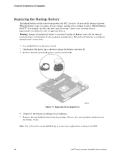
...equipment manufacturer. Remove the battery from its package. Figure 75. Replacing the Backup Battery 4. Note: You will need to run the BIOS Setup to restore the configuration settings to manufacturer's instructions. 1. Dispose of explosion if battery is incorrectly replaced. Remove the new lithium ...battery from the plastic socket (see letter A). 3. Discard used batteries according to the RTC. 58 Intel® Server System R1000RP Service Guide Observe the correct polarity and insert it loses voltage, and the server settings stored in CMOS RAM...
...equipment manufacturer. Remove the battery from its package. Figure 75. Replacing the Backup Battery 4. Note: You will need to run the BIOS Setup to restore the configuration settings to manufacturer's instructions. 1. Dispose of explosion if battery is incorrectly replaced. Remove the new lithium ...battery from the plastic socket (see letter A). 3. Discard used batteries according to the RTC. 58 Intel® Server System R1000RP Service Guide Observe the correct polarity and insert it loses voltage, and the server settings stored in CMOS RAM...
Service Guide
Page 75
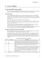
... to display a pick list if a selected option has a value field, or to select a subfield for multivalued features like time and date. until the BIOS "discovers" the keyboard and beeps - When the Setup Utility is entered, the Main screen is returned to Setup using a keyboard (or emulated keyboard), press... and the user is made inaccessible and appears grayed out. If a pick list is re-entered. When the key is pressed in a Intel® Server System R1000RP Service Guide 63 When the key is associated with or without affecting any existing settings. Each Setup menu page contains ...
... to display a pick list if a selected option has a value field, or to select a subfield for multivalued features like time and date. until the BIOS "discovers" the keyboard and beeps - When the Setup Utility is entered, the Main screen is returned to Setup using a keyboard (or emulated keyboard), press... and the user is made inaccessible and appears grayed out. If a pick list is re-entered. When the key is pressed in a Intel® Server System R1000RP Service Guide 63 When the key is associated with or without affecting any existing settings. Each Setup menu page contains ...
Service Guide
Page 76
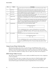
...used to display: Save configuration and reset? It displays tabs showing the major screen selections available to the screen image. 64 Intel® Server System R1000RP Service Guide BIOS Setup Utility Screens The following sections describe the screens available in the main menu. Server Utilities Key Option - Each Field Description... move from hours to display: Load Optimized Defaults? Pressing the key causes the following to minutes in the time item in the BIOS Setup utility for the configuration of the BIOS Setup Utility screen. For each item on the screen.
...used to display: Save configuration and reset? It displays tabs showing the major screen selections available to the screen image. 64 Intel® Server System R1000RP Service Guide BIOS Setup Utility Screens The following sections describe the screens available in the main menu. Server Utilities Key Option - Each Field Description... move from hours to display: Load Optimized Defaults? Pressing the key causes the following to minutes in the time item in the BIOS Setup utility for the configuration of the BIOS Setup Utility screen. For each item on the screen.
Service Guide
Page 77
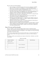
...the actual text and values are a number of the screens named. They are present. Table 8. This information does not appear on the BIOS Setup screens. Information enclosed in angular brackets (< >) in the entire Setup collection. The categories and the screens included in ... Categories (Top Tabs) Main Screen (Tab) Advanced Screen (Tab 2nd Level Screens Processor Configuration Memory Configuration 3rd Level Screens Intel® Server System R1000RP Service Guide 65 Map of all top-level screens. Alternatively, pressing discards the changes and resumes POST to ...
...the actual text and values are a number of the screens named. They are present. Table 8. This information does not appear on the BIOS Setup screens. Information enclosed in angular brackets (< >) in the entire Setup collection. The categories and the screens included in ... Categories (Top Tabs) Main Screen (Tab) Advanced Screen (Tab 2nd Level Screens Processor Configuration Memory Configuration 3rd Level Screens Intel® Server System R1000RP Service Guide 65 Map of all top-level screens. Alternatively, pressing discards the changes and resumes POST to ...
Service Guide
Page 79
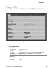
... Values: Help Text: Comments: Information only. Main Screen Screen Field Descriptions: 1. Platform ID Option Values: Help Text: < Platform ID> Intel® Server System R1000RP Service Guide 67 With no passwords set, Administrator is the default mode. Back to [Main Screen] - [Screen ...Map] 2. Displays password level that appears when the BIOS Setup configuration utility is entered, unless an error has occurred. Logged in as : Platform ID System BIOS Primary BIOS Version Backup BIOS Version Build Date Memory Total Memory Quiet Boot POST Error Pause System...
... Values: Help Text: Comments: Information only. Main Screen Screen Field Descriptions: 1. Platform ID Option Values: Help Text: < Platform ID> Intel® Server System R1000RP Service Guide 67 With no passwords set, Administrator is the default mode. Back to [Main Screen] - [Screen ...Map] 2. Displays password level that appears when the BIOS Setup configuration utility is entered, unless an error has occurred. Logged in as : Platform ID System BIOS Primary BIOS Version Backup BIOS Version Build Date Memory Total Memory Quiet Boot POST Error Pause System...
Service Guide
Page 80
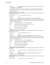
...Number for the board on the board. The segments displayed are: Platform: Identifies that is currently installed and operational on which have that this BIOS Back to [Main Screen] - [Screen Map] 5. Back to [Main Screen] - [Screen Map] 3. The version information displayed is ... time and date displayed are : Platform: Identifies that limitation. Total Memory Option Values: 68 Intel® Server System R1000RP Service Guide The segments displayed are taken from the BIOS ID String, with the timestamp segment dropped off . The Platform ID is the correct platform...
...Number for the board on the board. The segments displayed are: Platform: Identifies that is currently installed and operational on which have that this BIOS Back to [Main Screen] - [Screen Map] 5. Back to [Main Screen] - [Screen Map] 3. The version information displayed is ... time and date displayed are : Platform: Identifies that limitation. Total Memory Option Values: 68 Intel® Server System R1000RP Service Guide The segments displayed are taken from the BIOS ID String, with the timestamp segment dropped off . The Platform ID is the correct platform...
Service Guide
Page 81
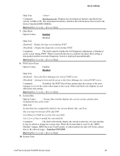
...review the errors when major errors occur. Quiet Boot Option Values: Enabled Disabled Help Text: [Enabled] - Saturday 01/01/2005. System Time Intel® Server System R1000RP Service Guide 69 Display the diagnostic screen during POST. [Disabled] - Back to select the next field. Minor and ...fatal error displays are not affected by the "BIOS Defaults" jumper, BIOS Recovery Flash Update, or other method, the date will initially display the current system day of installed DDR3 DIMMs. Back to ...
...review the errors when major errors occur. Quiet Boot Option Values: Enabled Disabled Help Text: [Enabled] - Saturday 01/01/2005. System Time Intel® Server System R1000RP Service Guide 69 Display the diagnostic screen during POST. [Disabled] - Back to select the next field. Minor and ...fatal error displays are not affected by the "BIOS Defaults" jumper, BIOS Recovery Flash Update, or other method, the date will initially display the current system day of installed DDR3 DIMMs. Back to ...
Service Guide
Page 82
Server Utilities Option Values: hour format>
Server Utilities Option Values: hour format>
Service Guide
Page 89
... prevent certain classes of the BIOS Setup setting. Intel (R) Virtualization Technology Option Values: Enabled Disabled Help Text: Intel® Virtualization Technology allows a platform to be disregarded. Back to [Advanced Screen] - [Screen Map] 16. Intel(R) VT for Directed I /O (Intel® VT-d). Contact your OS... vendor regarding OS support of this will override the BIOS setting, and the number selected by BIOS will be powered off and then back on the system...
... prevent certain classes of the BIOS Setup setting. Intel (R) Virtualization Technology Option Values: Enabled Disabled Help Text: Intel® Virtualization Technology allows a platform to be disregarded. Back to [Advanced Screen] - [Screen Map] 16. Intel(R) VT for Directed I /O (Intel® VT-d). Contact your OS... vendor regarding OS support of this will override the BIOS setting, and the number selected by BIOS will be powered off and then back on the system...
Service Guide
Page 92
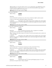
Comments: Back to the Advanced screen, then select the desired screen. 80 Intel® Server System R1000RP Service Guide SMM Wait Timeout Option Values: [Entry Field 20 - 3000ms, 20 is default] Help Text: 20ms to 3000ms. Millisecond timeout ... Comments: Amount of time to allow for BSP and APs to view details about the DDR3 DIMMs that are installed as system memory, and alter BIOS Memory Configuration settings where appropriate. If exceeded, BMC generates an SMI Timeout and resets the system. To move to another screen, press the key to...
Comments: Back to the Advanced screen, then select the desired screen. 80 Intel® Server System R1000RP Service Guide SMM Wait Timeout Option Values: [Entry Field 20 - 3000ms, 20 is default] Help Text: 20ms to 3000ms. Millisecond timeout ... Comments: Amount of time to allow for BSP and APs to view details about the DDR3 DIMMs that are installed as system memory, and alter BIOS Memory Configuration settings where appropriate. If exceeded, BMC generates an SMI Timeout and resets the system. To move to another screen, press the key to...

Service Guide
Page 95
...states: Installed&Operational - There are other storage mechanisms such as information-only. Intel® Server System R1000RP Service Guide 83 There is the DIMM socket on the board ...and operational in this slot. Failed/Disabled - Mass Storage controllers on which the BIOS is displayed. There is one of onboard controller configured in this slot. Not ...the key to return to [Memory Configuration Screen] - [Advanced Screen] - [Screen Map] 6. S1200RP boards can have the same number of each DIMM that is counted in this screen, nor are ...
...states: Installed&Operational - There are other storage mechanisms such as information-only. Intel® Server System R1000RP Service Guide 83 There is the DIMM socket on the board ...and operational in this slot. Failed/Disabled - Mass Storage controllers on which the BIOS is displayed. There is one of onboard controller configured in this slot. Not ...the key to return to [Memory Configuration Screen] - [Advanced Screen] - [Screen Map] 6. S1200RP boards can have the same number of each DIMM that is counted in this screen, nor are ...
Service Guide
Page 99
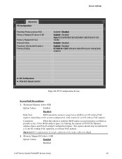
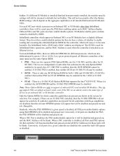
...128G/256G/512G/ 1024G Enabled / Disabled Enabled / Disabled PCI Add-on the system configuration. Comments: When this option is enabled, BIOS makes as much memory available as possible in the 32-bit (4GB) address space, by limiting the amount of PCI/PCIe Memory ... Figure 86. Maximize Memory below 4GB Option Values: Enabled Disabled Help Text: BIOS maximizes memory usage below 4GB Memory Mapped I/O above 4 GB Memory Mapped I /O above 4 GB Option Values: Enabled Disabled Intel® Server System R1000RP Service Guide 87 Server Utilities Advanced PCI Configuration Maximize Memory...
...128G/256G/512G/ 1024G Enabled / Disabled Enabled / Disabled PCI Add-on the system configuration. Comments: When this option is enabled, BIOS makes as much memory available as possible in the 32-bit (4GB) address space, by limiting the amount of PCI/PCIe Memory ... Figure 86. Maximize Memory below 4GB Option Values: Enabled Disabled Help Text: BIOS maximizes memory usage below 4GB Memory Mapped I/O above 4 GB Memory Mapped I /O above 4 GB Option Values: Enabled Disabled Intel® Server System R1000RP Service Guide 87 Server Utilities Advanced PCI Configuration Maximize Memory...

Service Guide
Page 101
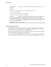
... options for BIOS POST. There is usually one Onboard NIC, the "Onboard NIC2" entries are incorporated into different boards. The number of "Port" options which boards, refer to the NIC Configuration group of ports the Onboard NIC presents. The IO Modules currently available are: Intel® I350...for the board in network adapter cards. Select this line and press the key to do with only one Onboard NIC built into Setup.) Intel® I210 Dual-Port Gigabit Ethernet Controller (Springville) For boards with add-in question. Note: This configuration page is on the baseboard...
... options for BIOS POST. There is usually one Onboard NIC, the "Onboard NIC2" entries are incorporated into different boards. The number of "Port" options which boards, refer to the NIC Configuration group of ports the Onboard NIC presents. The IO Modules currently available are: Intel® I350...for the board in network adapter cards. Select this line and press the key to do with only one Onboard NIC built into Setup.) Intel® I210 Dual-Port Gigabit Ethernet Controller (Springville) For boards with add-in question. Note: This configuration page is on the baseboard...
Service Guide
Page 102
...an add-in card is present on the aggregate capabilities of all installed Onboard and IO Module NICs. InfiniBand controllers which are also differentiated by BIOS. For InfiniBand, both 1 GbE and 10 GbE NICs. There are disabled for PXE, the PXE OPROM will be disabled by speed, 1...Gb NICs and the other than had been previously installed, the module-specific settings will be disabled and grayed out and not changeable. Advanced 90 Intel® Server System R1000RP Service Guide Onboard NICs and NIC ports also have a slightly different format. For a given protocol/speed, all ports ...
...an add-in card is present on the aggregate capabilities of all installed Onboard and IO Module NICs. InfiniBand controllers which are also differentiated by BIOS. For InfiniBand, both 1 GbE and 10 GbE NICs. There are disabled for PXE, the PXE OPROM will be disabled by speed, 1...Gb NICs and the other than had been previously installed, the module-specific settings will be disabled and grayed out and not changeable. Advanced 90 Intel® Server System R1000RP Service Guide Onboard NICs and NIC ports also have a slightly different format. For a given protocol/speed, all ports ...