
Service Guide
Page 5
...server board/chassis, a list of the Intel® Server System R1000RP family. Additional Information and Software For additional information about this manual provides technical specifications, regulatory information, LED Decoder, "getting help you identify your Intel® Server System. Product Safety and... required to add and replace components on the Intel® Server System R1000RP family products. In this manual, go to manage your system components and their supported accessories, refer to help " information, and Intel® Server Issue Report Form. Chapter 3 provides...
...server board/chassis, a list of the Intel® Server System R1000RP family. Additional Information and Software For additional information about this manual provides technical specifications, regulatory information, LED Decoder, "getting help you identify your Intel® Server System. Product Safety and... required to add and replace components on the Intel® Server System R1000RP family products. In this manual, go to manage your system components and their supported accessories, refer to help " information, and Intel® Server Issue Report Form. Chapter 3 provides...
Service Guide
Page 35
Intel® Server System R1000RP Service Guide 23 Tools and Supplies Needed Phillips* (cross head) screwdriver (#2 bit) Needle nosed pliers Anti-static wrist ... Before working with your server product, pay close attention to left, right, front, top, and bottom assume the reader is facing the front of this manual.
Intel® Server System R1000RP Service Guide 23 Tools and Supplies Needed Phillips* (cross head) screwdriver (#2 bit) Needle nosed pliers Anti-static wrist ... Before working with your server product, pay close attention to left, right, front, top, and bottom assume the reader is facing the front of this manual.
Service Guide
Page 132
... screen allows the user to configure the BMC Baseboard LAN channel and an Intel® RMM4 LAN channel, and to manage BMC User settings for IPv6-addressing. An Intel® RMM4 Management Module may be assigned by static IP addresses manually typed in, or by dynamic IP addresses supplied by "stateless autoconfiguration" which...
... screen allows the user to configure the BMC Baseboard LAN channel and an Intel® RMM4 LAN channel, and to manage BMC User settings for IPv6-addressing. An Intel® RMM4 Management Module may be assigned by static IP addresses manually typed in, or by dynamic IP addresses supplied by "stateless autoconfiguration" which...
Service Guide
Page 5
...the document or software name in the search field at : http://www.intel.com/support. Preface Preface About this Manual Thank you need , troubleshooting information, and instructions on how to help " information, and Intel® Server Issue Report Form. The back of this chapter, you ...identify components and their locations. For the latest version of the screen and select the option to http://www.intel.com/support. In this manual provides technical specifications, regulatory information, LED Decoder, "getting help you will find a list of the server chassis features,...
...the document or software name in the search field at : http://www.intel.com/support. Preface Preface About this Manual Thank you need , troubleshooting information, and instructions on how to help " information, and Intel® Server Issue Report Form. The back of this chapter, you ...identify components and their locations. For the latest version of the screen and select the option to http://www.intel.com/support. In this manual provides technical specifications, regulatory information, LED Decoder, "getting help you will find a list of the server chassis features,...

Service Guide
Page 24
... Before working with your server product, pay close attention to left, right, front, top, and bottom assume the reader is facing the front of this manual. Intel® Server System P4000RP Family Service Guide 11 NOTE Whenever you service the system, you must first power down the server and unplug all peripheral...
... Before working with your server product, pay close attention to left, right, front, top, and bottom assume the reader is facing the front of this manual. Intel® Server System P4000RP Family Service Guide 11 NOTE Whenever you service the system, you must first power down the server and unplug all peripheral...
Service Guide
Page 26
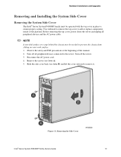
...skid surface or a stop behind the chassis may be operated with the top cover in place to add or replace components inside of this manual. 2. Observe the safety and ESD precautions at the beginning of the platform. Remove the screws (see letter B) and lift the cover outward ...Installations and Upgrades Removing and Installing the System Side Cover Removing the System Side Cover The Intel® Server System P4000RP family must be needed to remove it. Figure 11. Removing the Side Cover Intel® Server System P4000RP Family Service Guide 13 Disconnect the AC power cord. 4. You...
...skid surface or a stop behind the chassis may be operated with the top cover in place to add or replace components inside of this manual. 2. Observe the safety and ESD precautions at the beginning of the platform. Remove the screws (see letter B) and lift the cover outward ...Installations and Upgrades Removing and Installing the System Side Cover Removing the System Side Cover The Intel® Server System P4000RP family must be needed to remove it. Figure 11. Removing the Side Cover Intel® Server System P4000RP Family Service Guide 13 Disconnect the AC power cord. 4. You...
Service Guide
Page 28
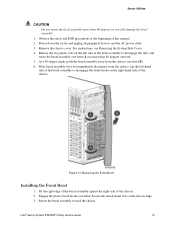
...A) into the raised metal slots at the beginning of the chassis. 2. Fit the right edge of the bezel assembly against the right side of this manual. 2. Power down the server and unplug all peripheral devices and the AC power cable. 3. For instructions, see letter A) no more than 40 degrees... 1. Engage the plastic bezel hooks (see letter B). 6. Observe the safety and ESD precautions at the chassis edge. 3. Remove the chassis cover. Intel® Server System P4000RP Family Service Guide 15 At a 40-degree angle, push the bezel assembly away from the chassis, tap the left-hand ...
...A) into the raised metal slots at the beginning of the chassis. 2. Fit the right edge of the bezel assembly against the right side of this manual. 2. Power down the server and unplug all peripheral devices and the AC power cable. 3. For instructions, see letter A) no more than 40 degrees... 1. Engage the plastic bezel hooks (see letter B). 6. Observe the safety and ESD precautions at the chassis edge. 3. Remove the chassis cover. Intel® Server System P4000RP Family Service Guide 15 At a 40-degree angle, push the bezel assembly away from the chassis, tap the left-hand ...
Service Guide
Page 36
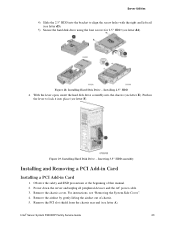
... and unplug all peripheral devices and the AC power cable. 3. Remove the airduct by gently lifting the airduct out of this manual. 2. Installing Hard Disk Drive - For instructions, see letter A). Intel® Server System P4000RP Family Service Guide 23 Push in Card 1. With the lever open, insert the hard disk drive assembly...
... and unplug all peripheral devices and the AC power cable. 3. Remove the airduct by gently lifting the airduct out of this manual. 2. Installing Hard Disk Drive - For instructions, see letter A). Intel® Server System P4000RP Family Service Guide 23 Push in Card 1. With the lever open, insert the hard disk drive assembly...
Service Guide
Page 38
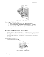
Observe the safety and ESD precautions at this manual. 2. Remove screw if there is one. 5. Remove the O filler (see Removing the System Side Cover. 4. Figure 33. For instructions, see letter A). Installing an Optical Drive 1. Remove the Optical Drive filler Intel® Server System P4000RP Family Service Guide 25 Remove the chassis cover. Gently...
Observe the safety and ESD precautions at this manual. 2. Remove screw if there is one. 5. Remove the O filler (see Removing the System Side Cover. 4. Figure 33. For instructions, see letter A). Installing an Optical Drive 1. Remove the Optical Drive filler Intel® Server System P4000RP Family Service Guide 25 Remove the chassis cover. Gently...
Service Guide
Page 44
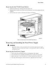
... Slide the battery from chassis components and server board. There are present inside it out of this manual. 2. Disconnect all peripheral devices and the AC power cable. 3. Server Utilities Removing the Intel® RAID Smart Battery 1. Pull the tab until the tab is disengaged from the server chassis... System Side Cover. 4. Figure 44. Observe the safety and ESD precautions at the beginning of the opening in the fan bulkhead. 3. Intel® Server System P4000RP Family Service Guide 31 Lift the battery up to remove it from the chassis cut. 2. servicing should be done...
... Slide the battery from chassis components and server board. There are present inside it out of this manual. 2. Disconnect all peripheral devices and the AC power cable. 3. Server Utilities Removing the Intel® RAID Smart Battery 1. Pull the tab until the tab is disengaged from the server chassis... System Side Cover. 4. Figure 44. Observe the safety and ESD precautions at the beginning of the opening in the fan bulkhead. 3. Intel® Server System P4000RP Family Service Guide 31 Lift the battery up to remove it from the chassis cut. 2. servicing should be done...
Service Guide
Page 46
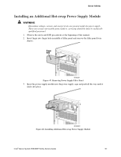
.... Figure 47. Insert the power supply module into finger hole in middle of this manual. 2. Insert finger into the power supply cage and push all the way until it ; Installing Additional Hot-swap Power Supply Module Intel® Server System P4000RP Family Service Guide 33 There are present inside it clicks into...
.... Figure 47. Insert the power supply module into finger hole in middle of this manual. 2. Insert finger into the power supply cage and push all the way until it ; Installing Additional Hot-swap Power Supply Module Intel® Server System P4000RP Family Service Guide 33 There are present inside it clicks into...
Service Guide
Page 47
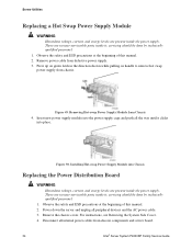
... done by technically qualified personnel. 1. Observe the safety and ESD precautions at the beginning of this manual. 2. Observe the safety and ESD precautions at the beginning of this manual. 2. There are no user-serviceable parts inside it ; Remove the chassis cover. Server Utilities Replacing... from chassis. There are no user-serviceable parts inside it ; Remove power cable from chassis components and server board. 34 Intel® Server System P4000RP Family Service Guide Figure 49. Power down the server and unplug all peripheral devices and the AC power...
... done by technically qualified personnel. 1. Observe the safety and ESD precautions at the beginning of this manual. 2. Observe the safety and ESD precautions at the beginning of this manual. 2. There are no user-serviceable parts inside it ; Remove the chassis cover. Server Utilities Replacing... from chassis. There are no user-serviceable parts inside it ; Remove power cable from chassis components and server board. 34 Intel® Server System P4000RP Family Service Guide Figure 49. Power down the server and unplug all peripheral devices and the AC power...
Service Guide
Page 53
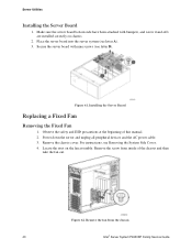
... precautions at the beginning of the chassis and then take the fan out. Remove the fan from inside of this manual. 2. For instructions, see letter A). 3. Remove the screw from the chassis 40 Intel® Server System P4000RP Family Service Guide Make sure the server board bottom side have been attached with nine...
... precautions at the beginning of the chassis and then take the fan out. Remove the fan from inside of this manual. 2. For instructions, see letter A). 3. Remove the screw from the chassis 40 Intel® Server System P4000RP Family Service Guide Make sure the server board bottom side have been attached with nine...
Service Guide
Page 54
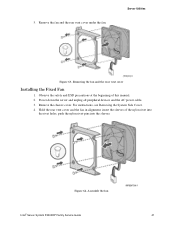
... and the rear vent cover Installing the Fixed Fan 1. Figure 64. Assemble the fan Intel® Server System P4000RP Family Service Guide 41 5. Hold the rear vent cover and the fan in alignment, insert the sleeves of this manual. 2. Power down the server and unplug all peripheral devices and the AC power...
... and the rear vent cover Installing the Fixed Fan 1. Figure 64. Assemble the fan Intel® Server System P4000RP Family Service Guide 41 5. Hold the rear vent cover and the fan in alignment, insert the sleeves of this manual. 2. Power down the server and unplug all peripheral devices and the AC power...
Service Guide
Page 55
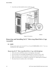
... Fix the fan Removing and Installing 8x3.5" Hot-swap Hard Drive Cage Assembly NOTE This procedure applies only to the backplane. 42 Intel® Server System P4000RP Family Service Guide Remove the chassis cover. Disconnect the power and data cables to the... Intel® Server System P4308RPLSHDR with Backplane 1. Observe the safety and ESD precautions at the beginning of this manual. 2. Remove the front bezel if it is installed. For instructions, see "Removing the Front Bezel...
... Fix the fan Removing and Installing 8x3.5" Hot-swap Hard Drive Cage Assembly NOTE This procedure applies only to the backplane. 42 Intel® Server System P4000RP Family Service Guide Remove the chassis cover. Disconnect the power and data cables to the... Intel® Server System P4308RPLSHDR with Backplane 1. Observe the safety and ESD precautions at the beginning of this manual. 2. Remove the front bezel if it is installed. For instructions, see "Removing the Front Bezel...
Service Guide
Page 56
... the hot-swap hard drive cage (see "Removing the Front Bezel". 5. Power down the server and unplug all peripheral devices and the AC power cable. 3. Intel® Server System P4000RP Family Service Guide 43 For instructions, see letter B). Observe the safety and ESD precautions at the beginning of this...
... the hot-swap hard drive cage (see "Removing the Front Bezel". 5. Power down the server and unplug all peripheral devices and the AC power cable. 3. Intel® Server System P4000RP Family Service Guide 43 For instructions, see letter B). Observe the safety and ESD precautions at the beginning of this...
Service Guide
Page 58
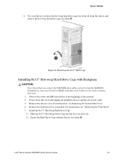
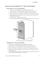
..., see Removing the System Side Cover. 4. Remove the front bezel if it is installed. Remove the 8x3.5" Hot-swap Hard drives cage. Intel® Server System P4000RP Family Service Guide 45 For instructions, see Removing the System Side Cover. 4. Figure 69. Remove the chassis cover. Server... the AC power cable. 3. For instructions, see "Removing the Front Bezel". 5. Observe the safety and ESD precautions at the beginning of this manual. 2. Remove the chassis cover. Remove the front bezel if it is installed. For instructions, see letter C). Remove the 8x3.5" Hot-swap Hard...
..., see Removing the System Side Cover. 4. Remove the front bezel if it is installed. Remove the 8x3.5" Hot-swap Hard drives cage. Intel® Server System P4000RP Family Service Guide 45 For instructions, see Removing the System Side Cover. 4. Figure 69. Remove the chassis cover. Server... the AC power cable. 3. For instructions, see "Removing the Front Bezel". 5. Observe the safety and ESD precautions at the beginning of this manual. 2. Remove the chassis cover. Remove the front bezel if it is installed. For instructions, see letter C). Remove the 8x3.5" Hot-swap Hard...
Service Guide
Page 59
... the AC power cable. 3. Observe the safety and ESD precautions at the beginning of this manual. 2. For instructions, see "Installing 8x3.5" Hotswap Hard Drive Cage". 9. Power up the server. Power down on its right side. 46 Intel® Server System P4000RP Family Service Guide For instructions, see "Installing the Front Bezel". 10...
... the AC power cable. 3. Observe the safety and ESD precautions at the beginning of this manual. 2. For instructions, see "Installing 8x3.5" Hotswap Hard Drive Cage". 9. Power up the server. Power down on its right side. 46 Intel® Server System P4000RP Family Service Guide For instructions, see "Installing the Front Bezel". 10...

Service Guide
Page 60
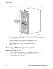
Observe the safety and ESD precautions at the beginning of this manual. 2. Lay the chassis down the server and unplug all four feet are removed. Figure 72. Installing the Chassis Feet 7. Removing the Chassis Feet 5. Installing the ... power cable. 3. Repeat above steps until all peripheral devices and the AC power cable to the chassis and then remove the rubber foot from chassis. Intel® Server System P4000RP Family Service Guide 47 Insert rubber foot into chassis hole (see letter B). 6. Power up the server. Loosen the screws securing the...
Observe the safety and ESD precautions at the beginning of this manual. 2. Lay the chassis down the server and unplug all four feet are removed. Figure 72. Installing the Chassis Feet 7. Removing the Chassis Feet 5. Installing the ... power cable. 3. Repeat above steps until all peripheral devices and the AC power cable to the chassis and then remove the rubber foot from chassis. Intel® Server System P4000RP Family Service Guide 47 Insert rubber foot into chassis hole (see letter B). 6. Power up the server. Loosen the screws securing the...
Service Guide
Page 61
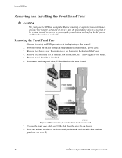
...safety and ESD precautions at the sides of the front panel (see letter A) and carefully slide the front panel out (see letter B). 48 Intel® Server System P4000RP Family Service Guide Power down the server and unplug all peripheral devices connected to the system, turn off the system by... cable and USB cable from the server board. Before removing or replacing the control panel, you must first take the server out of this manual. 2. For instructions, see Removing the System Side Cover. 4. Disconnecting the Cables from the system or wall outlet. For instructions, see "Removing ...
...safety and ESD precautions at the sides of the front panel (see letter A) and carefully slide the front panel out (see letter B). 48 Intel® Server System P4000RP Family Service Guide Power down the server and unplug all peripheral devices connected to the system, turn off the system by... cable and USB cable from the server board. Before removing or replacing the control panel, you must first take the server out of this manual. 2. For instructions, see Removing the System Side Cover. 4. Disconnecting the Cables from the system or wall outlet. For instructions, see "Removing ...