
Service Guide
Page 6
...Overview 2 Server System Components ...4 Hot Swap Hard Drive Bay and Front Panel Options 5 Front Panel...6 Back Panel...7 Server Board Components...8 Intel® Light-Guided Diagnostics 10 System Recovery Jumpers ...14 Peripheral Devices ...16 Hard Disk Drive Carriers...17 Slimline Optical Drive Support 18 Front... Air Duct 31 Removing the Air Duct 31 Installing the Air Duct 31 Removing and Installing Processor 32 Removing Processor Heatsink 32 Installing the Processor 32 Installing Processor Heatsink 35 Removing the Processor 36 vi Intel® Server System R1000RP Service Guide
...Overview 2 Server System Components ...4 Hot Swap Hard Drive Bay and Front Panel Options 5 Front Panel...6 Back Panel...7 Server Board Components...8 Intel® Light-Guided Diagnostics 10 System Recovery Jumpers ...14 Peripheral Devices ...16 Hard Disk Drive Carriers...17 Slimline Optical Drive Support 18 Front... Air Duct 31 Removing the Air Duct 31 Installing the Air Duct 31 Removing and Installing Processor 32 Removing Processor Heatsink 32 Installing the Processor 32 Installing Processor Heatsink 35 Removing the Processor 36 vi Intel® Server System R1000RP Service Guide
Service Guide
Page 8
... Selection Bar 64 BIOS Setup Utility Screens 64 Map of Screens and Functionality 65 Main Screen (Tab)...67 Advanced Screen (Tab 70 Processor Configuration 72 Memory Configuration 80 Mass Storage Controller Configuration 83 PCI Configuration...86 NIC Configuration ...89 Serial Port Configuration 97 USB Configuration ...... Specifications 147 Appendix B: Regulatory and Compliance Information 149 Appendix C: LED Decoder 150 Appendix D: Getting Help 154 Warranty Information 154 Appendix E: Intel® Server Issue Report Form 155 viii Intel® Server System R1000RP Service Guide
... Selection Bar 64 BIOS Setup Utility Screens 64 Map of Screens and Functionality 65 Main Screen (Tab)...67 Advanced Screen (Tab 70 Processor Configuration 72 Memory Configuration 80 Mass Storage Controller Configuration 83 PCI Configuration...86 NIC Configuration ...89 Serial Port Configuration 97 USB Configuration ...... Specifications 147 Appendix B: Regulatory and Compliance Information 149 Appendix C: LED Decoder 150 Appendix D: Getting Help 154 Warranty Information 154 Appendix E: Intel® Server Issue Report Form 155 viii Intel® Server System R1000RP Service Guide
Service Guide
Page 9
...Cover 30 Figure 26. Open the Socket Lever 33 Figure 31. Installing Processor - Installing Processor - Removing 3.5" HDD interface bracket 38 Figure 41. Installing Hard Disk Drive - Removing plastic drive blank 40 Figure 46. Intel® Server System R1000RP Components 4 Figure 3. 3.5" Fixed Hard Drive ...Backplane Components (Rear View 21 Figure 18. Intel® Light-Guided Diagnostic LEDs - Front view of Figures Figure 1. Cable Routing - 8 x 2.5" HDD 27 Figure 21. Removing the Air Duct...31 Figure 28. Removing Processor Heatsink 32 Figure 30. Remove the Cover 35...
...Cover 30 Figure 26. Open the Socket Lever 33 Figure 31. Installing Processor - Installing Processor - Removing 3.5" HDD interface bracket 38 Figure 41. Installing Hard Disk Drive - Removing plastic drive blank 40 Figure 46. Intel® Server System R1000RP Components 4 Figure 3. 3.5" Fixed Hard Drive ...Backplane Components (Rear View 21 Figure 18. Intel® Light-Guided Diagnostic LEDs - Front view of Figures Figure 1. Cable Routing - 8 x 2.5" HDD 27 Figure 21. Removing the Air Duct...31 Figure 28. Removing Processor Heatsink 32 Figure 30. Remove the Cover 35...

Service Guide
Page 10
...Key 49 Figure 61. Installing the Intel® RAID Smart Battery 53 Figure 66. Installing the fixed power supply module 54 Figure 69. Removing the redundant power supply module 55 Figure 70. Removing the Air Duct...56 Figure 72. Processor Configuration Screen 73 Figure 84. ...Rack Handle ...62 Figure 80. Advanced Screen...71 Figure 83. Mass Storage Controller Configuration Screen 84 Figure 86. CDROM Order Screen...134 x Intel® Server System R1000RP Service Guide List of Figures Figure 48. Installing an Optical Drive...46 Figure 56. Removing an I /O Expansion Module...
...Key 49 Figure 61. Installing the Intel® RAID Smart Battery 53 Figure 66. Installing the fixed power supply module 54 Figure 69. Removing the redundant power supply module 55 Figure 70. Removing the Air Duct...56 Figure 72. Processor Configuration Screen 73 Figure 84. ...Rack Handle ...62 Figure 80. Advanced Screen...71 Figure 83. Mass Storage Controller Configuration Screen 84 Figure 86. CDROM Order Screen...134 x Intel® Server System R1000RP Service Guide List of Figures Figure 48. Installing an Optical Drive...46 Figure 56. Removing an I /O Expansion Module...

Service Guide
Page 14
...provides SATA RAID 0/1/10 and optional RAID 5 support provided by the Intel® RAID Activation Key AXXRAKSW5. S1200V3RPL, S1200V3RPO, and S1200V3RPM support one Intel® Xeon® processor E3-1200 V3 processor in PCI Express* Slots Table 3. Server System Features Server System ...electrical with x8 physical connector, from PCH. Support for one optional internal SAS module connector which supports Intel® SAS or ROC modules with x8 physical connector, from processor. Slot 4: PCI Express* Gen2 x4 electrical with the product code of the server systems...
...provides SATA RAID 0/1/10 and optional RAID 5 support provided by the Intel® RAID Activation Key AXXRAKSW5. S1200V3RPL, S1200V3RPO, and S1200V3RPM support one Intel® Xeon® processor E3-1200 V3 processor in PCI Express* Slots Table 3. Server System Features Server System ...electrical with x8 physical connector, from PCH. Support for one optional internal SAS module connector which supports Intel® SAS or ROC modules with x8 physical connector, from processor. Slot 4: PCI Express* Gen2 x4 electrical with the product code of the server systems...

Service Guide
Page 15
...x8 PCIe Gen3 signals from the IO module of the processor. Form Factor microATX 9.6"x9.6" compliant form factor. AXXTPME5 (Accessory Option). Intel® Server System R1000RP Service Guide 3 Two Gigabit Ethernet Ports through the two Intel® Ethernet Controller I210. Two USB ...One internal Type-A USB 2.0 port. One 9 pin USB header for eUSB SSD. One 1x7 pin header for optional Intel® Local Control Panel support. One combined header consists of several available IO Module options. Server Management Integrated Baseboard Management...
...x8 PCIe Gen3 signals from the IO module of the processor. Form Factor microATX 9.6"x9.6" compliant form factor. AXXTPME5 (Accessory Option). Intel® Server System R1000RP Service Guide 3 Two Gigabit Ethernet Ports through the two Intel® Ethernet Controller I210. Two USB ...One internal Type-A USB 2.0 port. One 9 pin USB header for eUSB SSD. One 1x7 pin header for optional Intel® Local Control Panel support. One combined header consists of several available IO Module options. Server Management Integrated Baseboard Management...
Service Guide
Page 23
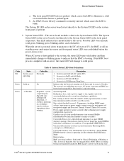
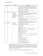
An IPMI Chassis Identify command is running (in this state Intel® Server System R1000RP Service Guide 11 The System Status LED on the server board is tied directly to indicate that the System is remotely ... until the button is operating in EuP Lot6 Off Mode. 3. Correctable memory error threshold has been reached for main power rail from power supply and Processor Thermal Control (Therm Ctrl) sensors. The front panel ID LED button is more DIMMs failed/disabled but has not transferred control to power supply, output...
An IPMI Chassis Identify command is running (in this state Intel® Server System R1000RP Service Guide 11 The System Status LED on the server board is tied directly to indicate that the System is remotely ... until the button is operating in EuP Lot6 Off Mode. 3. Correctable memory error threshold has been reached for main power rail from power supply and Processor Thermal Control (Therm Ctrl) sensors. The front panel ID LED button is more DIMMs failed/disabled but has not transferred control to power supply, output...
Service Guide
Page 24
... state (no good memory present. The following table defines the LED states during the BMC Boot/Reset process. 12 Intel® Server System R1000RP Service Guide Runtime memory uncorrectable error in a degraded state with an impending failure warning, although...command, and upon a BMC watchdog initiated reset. System in processor initialization: Processor family not identical Processor model not identical Processor core/thread counts not identical Processor cache size not identical Unable to synchronize processor frequency Unable to cool the system not present or failed. system...
... state (no good memory present. The following table defines the LED states during the BMC Boot/Reset process. 12 Intel® Server System R1000RP Service Guide Runtime memory uncorrectable error in a degraded state with an impending failure warning, although...command, and upon a BMC watchdog initiated reset. System in processor initialization: Processor family not identical Processor model not identical Processor core/thread counts not identical Processor cache size not identical Unable to synchronize processor frequency Unable to cool the system not present or failed. system...

Service Guide
Page 44
...underside of it by doing the following procedure: 1. Figure 29. For a web link to dissipate the static charge while handling the processor. b. Repeat steps A and B by giving each screw two rotations each time until all screws are loosened. 3. Lift the ...heatsink straight up (see "Additional Information and Software". 2. Avoid moving around unnecessarily. 32 Intel® Server System R1000RP Service Guide Similarly, loosen screws 3 and 4. Removing Processor Heatsink The heatsink is inappropriate for your body in a diagonal manner using the following : a. ...
...underside of it by doing the following procedure: 1. Figure 29. For a web link to dissipate the static charge while handling the processor. b. Repeat steps A and B by giving each screw two rotations each time until all screws are loosened. 3. Lift the ...heatsink straight up (see "Additional Information and Software". 2. Avoid moving around unnecessarily. 32 Intel® Server System R1000RP Service Guide Similarly, loosen screws 3 and 4. Removing Processor Heatsink The heatsink is inappropriate for your body in a diagonal manner using the following : a. ...

Service Guide
Page 45
... the socket pins if installed improperly. Note the location of the gold key at the corner of the processor; Install the Processor Note: The underside of the box and remove the protective shipping cover. Intel® Server System R1000RP Service Guide 33 Protective socket cover needs to open all the way (see letter...
... the socket pins if installed improperly. Note the location of the gold key at the corner of the processor; Install the Processor Note: The underside of the box and remove the protective shipping cover. Intel® Server System R1000RP Service Guide 33 Protective socket cover needs to open all the way (see letter...

Service Guide
Page 46
...latched (see letter A). Engage the Load Plate 6. Hardware Installations and Upgrades 4. Installing Processor - Close the Load Plate 5. Push down on the locking lever (see letter B). Figure 34. Installing Processor - Slide the tip of the load plate slides under the notch in the load plate.... Latch the Locking Lever 34 Intel® Server System R1000RP Service Guide Close the load plate locking lever ...
...latched (see letter A). Engage the Load Plate 6. Hardware Installations and Upgrades 4. Installing Processor - Close the Load Plate 5. Push down on the locking lever (see letter B). Figure 34. Installing Processor - Slide the tip of the load plate slides under the notch in the load plate.... Latch the Locking Lever 34 Intel® Server System R1000RP Service Guide Close the load plate locking lever ...

Service Guide
Page 47
... chassis for correct airflow. Remove the protective film on the TIM if present (see letter B). Figure 37. Installing Processor - Installing Processor Heatsink Intel® Server System R1000RP Service Guide 35 Remove the Cover Installing Processor Heatsink 1. Airflow goes from front-to screw 2 and engage screw threads by giving it two rotations and stop (see...
... chassis for correct airflow. Remove the protective film on the TIM if present (see letter B). Figure 37. Installing Processor - Installing Processor Heatsink Intel® Server System R1000RP Service Guide 35 Remove the Cover Installing Processor Heatsink 1. Airflow goes from front-to screw 2 and engage screw threads by giving it two rotations and stop (see...

Service Guide
Page 48
see Figure 30. 3. Open the load plate; see Figure 29. 2. Open the socket lever; Hardware Installations and Upgrades Removing the Processor 1. Remove the processor heatsink; see Figure 31. 4. Remove the processor. 36 Intel® Server System R1000RP Service Guide
see Figure 30. 3. Open the load plate; see Figure 29. 2. Open the socket lever; Hardware Installations and Upgrades Removing the Processor 1. Remove the processor heatsink; see Figure 31. 4. Remove the processor. 36 Intel® Server System R1000RP Service Guide
Service Guide
Page 77
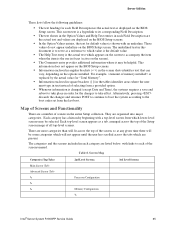
... be some categories which will be helpful. Screen Map Categories (Top Tabs) Main Screen (Tab) Advanced Screen (Tab 2nd Level Screens Processor Configuration Memory Configuration 3rd Level Screens Intel® Server System R1000RP Service Guide 65 Server Utilities These lists follow the following guidelines: The text heading for each Field...
... be some categories which will be helpful. Screen Map Categories (Top Tabs) Main Screen (Tab) Advanced Screen (Tab 2nd Level Screens Processor Configuration Memory Configuration 3rd Level Screens Intel® Server System R1000RP Service Guide 65 Server Utilities These lists follow the following guidelines: The text heading for each Field...
Service Guide
Page 83
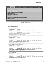
...View/Configure mass storage controller information and settings. Comments: Selection only. Back to [Advanced Screen] - [Screen Map] 2. Intel® Server System R1000RP Service Guide 71 Advanced Screen Screen Field Descriptions: 1. Back to [Advanced Screen] - [Screen Map...Back to the PCI Configuration group of configuration settings. Server Utilities Main Advanced Security Server Management Boot Options ► Processor Configuration ► Memory Configuration ► Mass Storage Controller Configuration ► PCI Configuration ► Serial Port Configuration ...
...View/Configure mass storage controller information and settings. Comments: Selection only. Back to [Advanced Screen] - [Screen Map] 2. Intel® Server System R1000RP Service Guide 71 Advanced Screen Screen Field Descriptions: 1. Back to [Advanced Screen] - [Screen Map...Back to the PCI Configuration group of configuration settings. Server Utilities Main Advanced Security Server Management Boot Options ► Processor Configuration ► Memory Configuration ► Mass Storage Controller Configuration ► PCI Configuration ► Serial Port Configuration ...

Service Guide
Page 84
... Configuration group of configuration settings. Select this line and press the key to go to the USB Configuration group of processor options. socket, and 4socket boards shown as the figure below. 72 Intel® Server System R1000RP Service Guide Comments: Selection only. It also allows the user to [Advanced Screen] - [Screen Map...
... Configuration group of configuration settings. Select this line and press the key to go to the USB Configuration group of processor options. socket, and 4socket boards shown as the figure below. 72 Intel® Server System R1000RP Service Guide Comments: Selection only. It also allows the user to [Advanced Screen] - [Screen Map...

Service Guide
Page 85
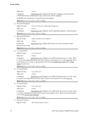
... Field Descriptions: 1. Server Utilities Advanced Processor Configuration Processor Socket Processor ID Processor Frequency Microcode Revision L1 Cache RAM L2 Cache RAM L3 Cache RAM Processor Version CPU Core Ratio Show CPU Core Ratio Intel(R) Turbo Boost Technology Enhanced Intel SpeedStep(R) Tech Processor C3 Processor C6 Intel(R) Hyper-Threading Tech Active Processor Cores Execute Disable Bit Intel (R) Virtualization Technology Intel(R) VT for Directed I/O Interrupt...
... Field Descriptions: 1. Server Utilities Advanced Processor Configuration Processor Socket Processor ID Processor Frequency Microcode Revision L1 Cache RAM L2 Cache RAM L3 Cache RAM Processor Version CPU Core Ratio Show CPU Core Ratio Intel(R) Turbo Boost Technology Enhanced Intel SpeedStep(R) Tech Processor C3 Processor C6 Intel(R) Hyper-Threading Tech Active Processor Cores Execute Disable Bit Intel (R) Virtualization Technology Intel(R) VT for Directed I/O Interrupt...
Service Guide
Page 86
...to [Advanced Screen] - [Screen Map] 4. Displays size in KB of L1 cache per core. Processor Version Option Values: 74 Intel® Server System R1000RP Service Guide L1 Cache RAM Option Values: Help Text: Comments: Information only.... Server Utilities Help Text: Comments: Information only. Displays the Processor Signature value (from the CPUID instruction) identifying the type of L2 cache per core. S1200RP series boards have a single Processor...
...to [Advanced Screen] - [Screen Map] 4. Displays size in KB of L1 cache per core. Processor Version Option Values: 74 Intel® Server System R1000RP Service Guide L1 Cache RAM Option Values: Help Text: Comments: Information only.... Server Utilities Help Text: Comments: Information only. Displays the Processor Signature value (from the CPUID instruction) identifying the type of L2 cache per core. S1200RP series boards have a single Processor...

Service Guide
Page 87
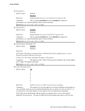
... option is only visible if all processors installed in the system support Intel® Turbo Boost Technology. Intel(R) Turbo Boost Technology Option Values: Enabled Disabled Help Text: Intel® Turbo Boost Technology allows the processor to automatically increase its frequency if ...Core Ratio Multiplier. 0 - 63. In order for the Intel® Turbo Boost option to be available, Enhanced Intel® SpeedStep® Technology must be Enabled. In order for this feature. Comments: When Disabled, the processor setting reverts to [Advanced Screen] - [Screen Map] ...
... option is only visible if all processors installed in the system support Intel® Turbo Boost Technology. Intel(R) Turbo Boost Technology Option Values: Enabled Disabled Help Text: Intel® Turbo Boost Technology allows the processor to automatically increase its frequency if ...Core Ratio Multiplier. 0 - 63. In order for the Intel® Turbo Boost option to be available, Enhanced Intel® SpeedStep® Technology must be Enabled. In order for this feature. Comments: When Disabled, the processor setting reverts to [Advanced Screen] - [Screen Map] ...
Service Guide
Page 88
... the number previously set by the user. 76 Intel® Server System R1000RP Service Guide Comments: The numbers of cores available in each processor. Back to execute threads in the system support Intel® Hyper-Threading Technology. Intel(R) Hyper-Threading Tech Option Values: Enabled Disabled Help Text: Intel® Hyper-Threading Technology allows multithreaded software...
... the number previously set by the user. 76 Intel® Server System R1000RP Service Guide Comments: The numbers of cores available in each processor. Back to execute threads in the system support Intel® Hyper-Threading Technology. Intel(R) Hyper-Threading Tech Option Values: Enabled Disabled Help Text: Intel® Hyper-Threading Technology allows multithreaded software...