
Service Guide
Page 3
...antes de realizar ® cualquiera de las instrucciones. Vea Intel Server Boards and Server Chassis Safety Information en el Intel® Server Deployment Toolkit DVD y/o en http://www.intel.com/support/motherboards/server/sb/cs-010770.htm. Wichtige Sicherheitshinweise Lesen Sie ...intel.com/support/motherboards/server/sb/cs-010770.htm. http://www.intel.com/support/motherboards/server/sb/cs-010770.htm 上的 ® Intel Server Boards and Server Chassis Safety Information(《Intel Intel® Server System R1000RP Service Guide iii Consultez Intel...
...antes de realizar ® cualquiera de las instrucciones. Vea Intel Server Boards and Server Chassis Safety Information en el Intel® Server Deployment Toolkit DVD y/o en http://www.intel.com/support/motherboards/server/sb/cs-010770.htm. Wichtige Sicherheitshinweise Lesen Sie ...intel.com/support/motherboards/server/sb/cs-010770.htm. http://www.intel.com/support/motherboards/server/sb/cs-010770.htm 上的 ® Intel Server Boards and Server Chassis Safety Information(《Intel Intel® Server System R1000RP Service Guide iii Consultez Intel...
Service Guide
Page 9
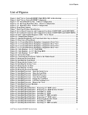
... Hard Drive Backplane Components (Rear View 21 Figure 18. Server Board Connector and Component Locations (S1200V3RPL and S1200V3RPS)..... 8 Figure 9. Intel® Light-Guided Diagnostic LEDs - Connecting the Fan Power Cables to the Motherboard 28 Figure 23. Installing Processor - Installing 2.5" HDD 40 Figure 47. Removing Processor Heatsink 32 Figure 30. Installing Processor - Close...
... Hard Drive Backplane Components (Rear View 21 Figure 18. Server Board Connector and Component Locations (S1200V3RPL and S1200V3RPS)..... 8 Figure 9. Intel® Light-Guided Diagnostic LEDs - Connecting the Fan Power Cables to the Motherboard 28 Figure 23. Installing Processor - Installing 2.5" HDD 40 Figure 47. Removing Processor Heatsink 32 Figure 30. Installing Processor - Close...
Service Guide
Page 25
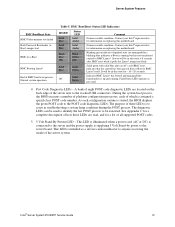
...assigned a specific hex POST code number. A bank of eight POST code diagnostic LEDs are read, and for information on replacing this motherboard. BMC Boot/Reset Status LED Indicators ID LED Solid Blue Solid Blue Blink Blue 3Hz Status LED Solid Amber Solid Amber Blink Green .... 4. The purpose of all supported POST codes. 5. 5 Volt Stand-By Present LED - Contact your Intel® representative for a list of these LEDs are located on replacing this motherboard. Solid green with solid blue after BMC reset while it pulls the Linux* image into flash. Server will...
...assigned a specific hex POST code number. A bank of eight POST code diagnostic LEDs are read, and for information on replacing this motherboard. BMC Boot/Reset Status LED Indicators ID LED Solid Blue Solid Blue Blink Blue 3Hz Status LED Solid Amber Solid Amber Blink Green .... 4. The purpose of all supported POST codes. 5. 5 Volt Stand-By Present LED - Contact your Intel® representative for a list of these LEDs are located on replacing this motherboard. Solid green with solid blue after BMC reset while it pulls the Linux* image into flash. Server will...

Service Guide
Page 32
Server System Features Hot-Swap SAS/SATA Backplane The Hot-Swap SAS/SATA backplane serves as an interface between the motherboard and the system drives. The following diagrams show the location for each connector found on the backplane. 4 x 3.5-inch Hard Drive Backplane A SAS/SATA Hot-swap ... Hard Drive Backplane Components (Rear View) 8 x 2.5-inch Hard Drive Backplane A SAS/SATA Hot-swap Connectors Figure 16. 8 x 2.5-inch Hard Drive Backplane Components (Front View) 20 Intel® Server System R1000RP Service Guide
Server System Features Hot-Swap SAS/SATA Backplane The Hot-Swap SAS/SATA backplane serves as an interface between the motherboard and the system drives. The following diagrams show the location for each connector found on the backplane. 4 x 3.5-inch Hard Drive Backplane A SAS/SATA Hot-swap ... Hard Drive Backplane Components (Rear View) 8 x 2.5-inch Hard Drive Backplane A SAS/SATA Hot-swap Connectors Figure 16. 8 x 2.5-inch Hard Drive Backplane Components (Front View) 20 Intel® Server System R1000RP Service Guide

Service Guide
Page 40
Connecting the Fan Power Cables to determine the proper fan connections. Hardware Installations and Upgrades Fan Connections Use the following figures to the Motherboard 28 Intel® Server System R1000RP Service Guide Figure 21. System Fan Order Figure 22.
Connecting the Fan Power Cables to determine the proper fan connections. Hardware Installations and Upgrades Fan Connections Use the following figures to the Motherboard 28 Intel® Server System R1000RP Service Guide Figure 21. System Fan Order Figure 22.

Service Guide
Page 61
Figure 60. Removing the Intel® ESRTII SATA Key Intel® Server System R1000RP Service Guide 49 Figure 59. Match the Key and connector and press down to remove it from the motherboard. Carefully pick up the key to install. Installing the Intel® ESRTII SATA Key Removing the Intel® ESRTII SATA Key Pull up the Intel® ESRTII SATA Key. Hardware Installations and Upgrades Installing and Removing the Intel® ESRTII SATA Key Installing the Intel® ESRTII SATA Key Locate the white 4-pin key header next to the POST diagnostic LEDs.
Figure 60. Removing the Intel® ESRTII SATA Key Intel® Server System R1000RP Service Guide 49 Figure 59. Match the Key and connector and press down to remove it from the motherboard. Carefully pick up the key to install. Installing the Intel® ESRTII SATA Key Removing the Intel® ESRTII SATA Key Pull up the Intel® ESRTII SATA Key. Hardware Installations and Upgrades Installing and Removing the Intel® ESRTII SATA Key Installing the Intel® ESRTII SATA Key Locate the white 4-pin key header next to the POST diagnostic LEDs.

Service Guide
Page 64
Figure 63. Figure 64. Disconnect the flex cable from the RMM4 connector on the server board (see letter A). 2. Removing the Intel® RMM4 NIC 52 Intel® Server System R1000RP Service Guide Remove the two screws as shown (see letter C). Removing the Intel® RMM4 Lite Removing the Intel® RMM4 NIC 1. Disconnect the opposite end of the flex cable from the RMM4 connector on the RMM4 NIC module (see letter B). 3. Hardware Installations and Upgrades Removing the Intel® RMM4 Lite Pull up the RMM4 Lite module to remove it from the motherboard.
Figure 63. Figure 64. Disconnect the flex cable from the RMM4 connector on the server board (see letter A). 2. Removing the Intel® RMM4 NIC 52 Intel® Server System R1000RP Service Guide Remove the two screws as shown (see letter C). Removing the Intel® RMM4 Lite Removing the Intel® RMM4 NIC 1. Disconnect the opposite end of the flex cable from the RMM4 connector on the RMM4 NIC module (see letter B). 3. Hardware Installations and Upgrades Removing the Intel® RMM4 Lite Pull up the RMM4 Lite module to remove it from the motherboard.

Service Guide
Page 3
...; Server Deployment Toolkit DVD and/or at http://www.intel.com/support/motherboards/server/sb/cs-010770.htm. http://www.intel.com/support/motherboards/server/sb/cs-010770.htm 上的 Intel® Server Boards and Server Chassis Safety Information(《Intel Intel® Server System P4000RP Family Service Guide iii Safety Information Safety Information Important...
...; Server Deployment Toolkit DVD and/or at http://www.intel.com/support/motherboards/server/sb/cs-010770.htm. http://www.intel.com/support/motherboards/server/sb/cs-010770.htm 上的 Intel® Server Boards and Server Chassis Safety Information(《Intel Intel® Server System P4000RP Family Service Guide iii Safety Information Safety Information Important...

Service Guide
Page 21
...; representative for information on replacing this motherboard. Fault/Status LEDs operate as per usual. Configuration Jumpers 8 Intel® Server System P4000RP Family Service Guide Normal system operation ID LED Solid Blue Solid Blue Blink Blue 3Hz Status LED Solid Amber...reset, indicates that the control has been passed from u-Boot to BMC Linux*. It will be in this state for information on replacing this motherboard. Indicates BMC Linux* has booted and manageability functionality is running . Server System Features BMC Boot/Reset State BMC/Video memory test failed Both ...
...; representative for information on replacing this motherboard. Fault/Status LEDs operate as per usual. Configuration Jumpers 8 Intel® Server System P4000RP Family Service Guide Normal system operation ID LED Solid Blue Solid Blue Blink Blue 3Hz Status LED Solid Amber...reset, indicates that the control has been passed from u-Boot to BMC Linux*. It will be in this state for information on replacing this motherboard. Indicates BMC Linux* has booted and manageability functionality is running . Server System Features BMC Boot/Reset State BMC/Video memory test failed Both ...

Service Guide
Page 66
Removing the Alternate Serial Port Knockout 5. Figure 83. Server Utilities 4. Install the serial port on your motherboard. Installing the Alternate Serial Port Knockout Intel® Server System P4000RP Family Service Guide 53 And connect the cable to the Serial B Connector on the rear panel of the chassis. Remove the alternate serial port knockout by pressing the knockout from inside the chassis. Figure 82.
Removing the Alternate Serial Port Knockout 5. Figure 83. Server Utilities 4. Install the serial port on your motherboard. Installing the Alternate Serial Port Knockout Intel® Server System P4000RP Family Service Guide 53 And connect the cable to the Serial B Connector on the rear panel of the chassis. Remove the alternate serial port knockout by pressing the knockout from inside the chassis. Figure 82.
Technical Product Specification
Page 37
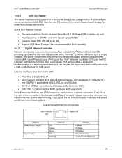
...Gigabit Ethernet Controller Network connectivity is used for server and client configurations as defined in the following table. The Intel® Ethernet Controller I210 is NOT supported) Each Ethernet port drives two LEDs located on each network interface ... architecture from 256 MB to plug this small flash storage device into. The LED at the right of two onboard Intel® Ethernet Controller I210 providing up to a Manageability Controller (MC) EEE 1149.1 JTAG (note that ...connector is the link/activity LED and indicates network connection when on Motherboard (LOM) design.
...Gigabit Ethernet Controller Network connectivity is used for server and client configurations as defined in the following table. The Intel® Ethernet Controller I210 is NOT supported) Each Ethernet port drives two LEDs located on each network interface ... architecture from 256 MB to plug this small flash storage device into. The LED at the right of two onboard Intel® Ethernet Controller I210 providing up to a Manageability Controller (MC) EEE 1149.1 JTAG (note that ...connector is the link/activity LED and indicates network connection when on Motherboard (LOM) design.

Technical Product Specification
Page 215
...* has booted and manageability functionality is running . The purpose of these LEDs are read, and for information on replacing this motherboard. The following table defines the LED states during the POST process. Blinking green indicates degraded state (no manageability), blinking blue ... occur when AC power is started, the BIOS displays the given POST code to the stacked USB connectors. Intel® Server Board S1200V3RP Intel® Light Guided Diagnostics Color State Criticality Description 240VA fault Fatal Error in processor initialization: Processor family not ...
...* has booted and manageability functionality is running . The purpose of these LEDs are read, and for information on replacing this motherboard. The following table defines the LED states during the POST process. Blinking green indicates degraded state (no manageability), blinking blue ... occur when AC power is started, the BIOS displays the given POST code to the stacked USB connectors. Intel® Server Board S1200V3RP Intel® Light Guided Diagnostics Color State Criticality Description 240VA fault Fatal Error in processor initialization: Processor family not ...
Technical Product Specification
Page 22
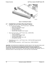
... Cable Management Arm - Installing Front Bezel 2.7 Available Rack and Cabinet Mounting Kit Options Tool-less rack mount rail kit - Intel® Product Code - AXXELVRAIL o 1U to 4U compatible o 110 lbs maximum support weight o Tool-less chassis attach o Tools required to attach... - AXX2POSTBRCKT CAUTION: THE MAXIMUM RECOMMENDED SERVER WEIGHT FOR THE RACK RAILS CAN BE FOUND at http://www.intel.com/support/motherboards/server/sb/CS-033655.htm. Intel® Product Code - EXCEEDING THE MAXIMUM RECOMMENDED WEIGHT OR MISALIGNMENT OF THE SERVER MAY RESULT IN FAILURE ...
... Cable Management Arm - Installing Front Bezel 2.7 Available Rack and Cabinet Mounting Kit Options Tool-less rack mount rail kit - Intel® Product Code - AXXELVRAIL o 1U to 4U compatible o 110 lbs maximum support weight o Tool-less chassis attach o Tools required to attach... - AXX2POSTBRCKT CAUTION: THE MAXIMUM RECOMMENDED SERVER WEIGHT FOR THE RACK RAILS CAN BE FOUND at http://www.intel.com/support/motherboards/server/sb/CS-033655.htm. Intel® Product Code - EXCEEDING THE MAXIMUM RECOMMENDED WEIGHT OR MISALIGNMENT OF THE SERVER MAY RESULT IN FAILURE ...

Technical Product Specification
Page 50
..., and RMS25JB040. S1200V3RPO and S1200V3RPM support one optional internal SAS module connector which supports Intel® SAS or ROC modules with the product code of possible storage configurations. Intel® RSTe SW RAID through onboard SATA connectors provides SATA RAID 0/1/10 and optional... the different options available. 6.1 Embedded SATA Controller Support There are six 6Gb/s SATA ports on the motherboard. This section provides an overview of "SATA_KEY". Intel® Embedded Server RAID Technology II through onboard SATA connectors provides SATA RAID 0/1/10/5. Figure 34. ...
..., and RMS25JB040. S1200V3RPO and S1200V3RPM support one optional internal SAS module connector which supports Intel® SAS or ROC modules with the product code of possible storage configurations. Intel® RSTe SW RAID through onboard SATA connectors provides SATA RAID 0/1/10 and optional... the different options available. 6.1 Embedded SATA Controller Support There are six 6Gb/s SATA ports on the motherboard. This section provides an overview of "SATA_KEY". Intel® Embedded Server RAID Technology II through onboard SATA connectors provides SATA RAID 0/1/10/5. Figure 34. ...

Technical Product Specification
Page 64
...; Server System R1000RP Family TPS 9 PCIe Support and Riser Card Support Intel® Server System R1304RPOSHBN, R1208RPOSHOR, and R1208RPMSHOR provide one PCI Express* x16 slot through one riser card. 9.1 Architectural Overview of the Server Board Riser ...Express* Gen2 x8 PCI Express* Gen2 x4 PCI Express* Gen2 x4 54 Intel order number: G91532-003 Revision 1.2 Intel® Server System R1304RPSSFBN provides one PCI Express* x8 slot through Riser card S1200V3RPS R1304RPSSFBN PCI Express* Gen3 x8 on the three motherboards and the mapping to the systems. Table 29. PCI Express* Speed...
...; Server System R1000RP Family TPS 9 PCIe Support and Riser Card Support Intel® Server System R1304RPOSHBN, R1208RPOSHOR, and R1208RPMSHOR provide one PCI Express* x16 slot through one riser card. 9.1 Architectural Overview of the Server Board Riser ...Express* Gen2 x8 PCI Express* Gen2 x4 PCI Express* Gen2 x4 54 Intel order number: G91532-003 Revision 1.2 Intel® Server System R1304RPSSFBN provides one PCI Express* x8 slot through Riser card S1200V3RPS R1304RPSSFBN PCI Express* Gen3 x8 on the three motherboards and the mapping to the systems. Table 29. PCI Express* Speed...