Design Guidelines
Page 6
...Thermal Profile 18 Figure 4. Thermal Monitor 2 Frequency and Voltage Ordering 34 Figure 10. Intel® ALCT Reference Design Major Components 53 Figure 17. Intel® Quiet System Technology Overview 58 Figure 22. Digital Thermal Sensor and Thermistor 62 ...14. CPU Maximum Current Draw for Clocks under Thermal Monitor Control 33 Figure 9. Processor Thermal Characterization Parameter Relationships 24 Figure 5. Securing Thermocouple Wires with Kapton* Tape Prior to Motherboard Interface 54 Figure 19. Locations for Measuring Local Ambient Temperature, Passive Heatsink...
...Thermal Profile 18 Figure 4. Thermal Monitor 2 Frequency and Voltage Ordering 34 Figure 10. Intel® ALCT Reference Design Major Components 53 Figure 17. Intel® Quiet System Technology Overview 58 Figure 22. Digital Thermal Sensor and Thermistor 62 ...14. CPU Maximum Current Draw for Clocks under Thermal Monitor Control 33 Figure 9. Processor Thermal Characterization Parameter Relationships 24 Figure 5. Securing Thermocouple Wires with Kapton* Tape Prior to Motherboard Interface 54 Figure 19. Locations for Measuring Local Ambient Temperature, Passive Heatsink...

Design Guidelines
Page 7
.... Typical Test Equipment 72 Table 12. Intel Reference Component ATX Thermal Solution Providers 123 Thermal and Mechanical Design Guidelines 7 Temperature Range = 5 °C 101 Figure 61. System Airflow Illustration with Adhesive 93 Figure 53. Sheet 3 116 Figure 69. Balanced Technology Extended (BTX) Thermal Module Keep Out Volumetric - Maximum Estimated Processor Current Capability at 35 º...
.... Typical Test Equipment 72 Table 12. Intel Reference Component ATX Thermal Solution Providers 123 Thermal and Mechanical Design Guidelines 7 Temperature Range = 5 °C 101 Figure 61. System Airflow Illustration with Adhesive 93 Figure 53. Sheet 3 116 Figure 69. Balanced Technology Extended (BTX) Thermal Module Keep Out Volumetric - Maximum Estimated Processor Current Capability at 35 º...

Design Guidelines
Page 9
...form factor. Temperatures exceeding the maximum operating limit of a component may be the Intel enabled reference solution for ATX/uATX systems. See the applicable BTX form factor reference documents to design a thermal solution for the processor. The .... Thermal and Mechanical Design Guidelines 9 The processor temperature depends in particular on single processor systems using the Intel® Core™2 Extreme processor QX6800 B3 Stepping and Intel® Core™2 Extreme processor QX9770 C0 Stepping. The goal of this temperature range, a component is expected to meet ...
...form factor. Temperatures exceeding the maximum operating limit of a component may be the Intel enabled reference solution for ATX/uATX systems. See the applicable BTX form factor reference documents to design a thermal solution for the processor. The .... Thermal and Mechanical Design Guidelines 9 The processor temperature depends in particular on single processor systems using the Intel® Core™2 Extreme processor QX6800 B3 Stepping and Intel® Core™2 Extreme processor QX9770 C0 Stepping. The goal of this temperature range, a component is expected to meet ...
Design Guidelines
Page 10
... dissipation and maximum case temperature. LGA775 Socket Heatsink Loading 1.1.3 Document Scope This design guide supports the following processor: • Intel® Core™2 Extreme processor QX6800 B3 Stepping • Intel® Core™2 Extreme processor QX9770 C0 Stepping In this document when a reference is made to "the datasheet", the reader should refer to the Intel® Core™2 Extreme Processor QX9000 Series and Intel® Core™2 Quad Processor Q9000...
... dissipation and maximum case temperature. LGA775 Socket Heatsink Loading 1.1.3 Document Scope This design guide supports the following processor: • Intel® Core™2 Extreme processor QX6800 B3 Stepping • Intel® Core™2 Extreme processor QX9770 C0 Stepping In this document when a reference is made to "the datasheet", the reader should refer to the Intel® Core™2 Extreme Processor QX9000 Series and Intel® Core™2 Quad Processor Q9000...
Design Guidelines
Page 11
... source must be specified for Ψ measurements. Document Intel® Core™2 Extreme Processor QX9000 Series and Intel® Core™2 Quad Processor Q9000 Series Datasheet Intel® Core™2 Extreme Quad-Core Processor QX6000Δ Sequence and Intel® Core™2 Quad Processor Q6000Δ Sequence Datasheet LGA775 Socket Mechanical Design Guide Fan Specification for Ψ measurements. The case temperature of Terms Term Description TA TC TE TS...
... source must be specified for Ψ measurements. Document Intel® Core™2 Extreme Processor QX9000 Series and Intel® Core™2 Quad Processor Q9000 Series Datasheet Intel® Core™2 Extreme Quad-Core Processor QX6000Δ Sequence and Intel® Core™2 Quad Processor Q6000Δ Sequence Datasheet LGA775 Socket Mechanical Design Guide Fan Specification for Ψ measurements. The case temperature of Terms Term Description TA TC TE TS...
Design Guidelines
Page 12
... designed to a thermal solution through heat spreading. Thermal Control Circuit: Thermal Monitor uses the TCC to reduce die temperature by a semiconductor component. The maximum power dissipated by lowering effective processor frequency when the die temperature has exceeded its operating limits. ACPI Bypass Thermal Monitor TCC DTS TDIODE FSC TCONTROL_BASE TCONTROL_OFFSET TCONTROL PWM Health Monitor...
... designed to a thermal solution through heat spreading. Thermal Control Circuit: Thermal Monitor uses the TCC to reduce die temperature by a semiconductor component. The maximum power dissipated by lowering effective processor frequency when the die temperature has exceeded its operating limits. ACPI Bypass Thermal Monitor TCC DTS TDIODE FSC TCONTROL_BASE TCONTROL_OFFSET TCONTROL PWM Health Monitor...

Design Guidelines
Page 16
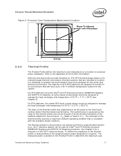
.... The majority of the IHS. The Thermal Profile defines the maximum case temperature as the temperature measured at the geometric center of the package on the surface of processor power is usually minimal. There are given in Section 3.4. Designing to the datasheet for the processor thermal specifications. Note that are no additional components, e.g., BSRAMs, which...
.... The majority of the IHS. The Thermal Profile defines the maximum case temperature as the temperature measured at the geometric center of the package on the surface of processor power is usually minimal. There are given in Section 3.4. Designing to the datasheet for the processor thermal specifications. Note that are no additional components, e.g., BSRAMs, which...
Design Guidelines
Page 17
... thermal environment, thermal solutions that will have up to a 35 °C ambient temperature external to Section 3.1). See Chapter 5 for Intel® Core™2 Extreme processor QX6800 B3 Stepping and QX9770 C0 Stepping processors. For ATX platforms using the Intel® Core™2 Extreme processor QX6800 B3 stepping and QX9770 C0 stepping, an active liquid-cooled design should be thought of as the...
... thermal environment, thermal solutions that will have up to a 35 °C ambient temperature external to Section 3.1). See Chapter 5 for Intel® Core™2 Extreme processor QX6800 B3 Stepping and QX9770 C0 Stepping processors. For ATX platforms using the Intel® Core™2 Extreme processor QX6800 B3 stepping and QX9770 C0 stepping, an active liquid-cooled design should be thought of as the...

Design Guidelines
Page 18
...Heatsink Loading temperature. See the datasheet for the discussion the thermal management logic and features and Chapter 6 on Intel® Quiet System Technology (Intel® QST). One of the most significant of TCONTROL when running the same application. As a result a processor with lower... will always be a negative number. Figure 3. Example Thermal Profile 2.2.3 TCONTROL TCONTROL defines the maximum operating temperature for a processor dissipating 110W the maximum case temperature is driven by a higher value of factors. Using the example in the acoustic performance. 18...
...Heatsink Loading temperature. See the datasheet for the discussion the thermal management logic and features and Chapter 6 on Intel® Quiet System Technology (Intel® QST). One of the most significant of TCONTROL when running the same application. As a result a processor with lower... will always be a negative number. Figure 3. Example Thermal Profile 2.2.3 TCONTROL TCONTROL defines the maximum operating temperature for a processor dissipating 110W the maximum case temperature is driven by a higher value of factors. Using the example in the acoustic performance. 18...

Design Guidelines
Page 21
... it . The number, size and relative position of Intel Reference Thermal Solutions Topic Heatsink Inlet Temperature ATX ALCT 38 °C BTX Liquid Cooling 35.5 °C 2.4.2 Improving Chassis Thermal Performance The heat generated by the processor and other system components. In addition to provide an ... generated by components within the chassis must be traded off against each other solutions that chassis delivers a maximum TA at the inlet of the processor heat exchanger (refer to compensate for cooling integrated circuit devices. All thermal interface materials should be pre-...
... it . The number, size and relative position of Intel Reference Thermal Solutions Topic Heatsink Inlet Temperature ATX ALCT 38 °C BTX Liquid Cooling 35.5 °C 2.4.2 Improving Chassis Thermal Performance The heat generated by the processor and other system components. In addition to provide an ... generated by components within the chassis must be traded off against each other solutions that chassis delivers a maximum TA at the inlet of the processor heat exchanger (refer to compensate for cooling integrated circuit devices. All thermal interface materials should be pre-...

Design Guidelines
Page 22
...roughness. • The performance of these solutions may reduce thermal solution cost by the system System Integration Considerations Manufacturing with Intel® Components using 775-Land LGA Package and LGA775 Socket documentation provides Best Known Methods for a particular system implementation. ... should be appropriate for all capable of the processor, and the corresponding maximum TC as calculated from the thermal profile. Summary In summary, considerations in heatsink design include: • The local ambient temperature TA at the entire system level, accounting for...
...roughness. • The performance of these solutions may reduce thermal solution cost by the system System Integration Considerations Manufacturing with Intel® Components using 775-Land LGA Package and LGA775 Socket documentation provides Best Known Methods for a particular system implementation. ... should be appropriate for all capable of the processor, and the corresponding maximum TC as calculated from the thermal profile. Summary In summary, considerations in heatsink design include: • The local ambient temperature TA at the entire system level, accounting for...

Design Guidelines
Page 25
...Intel processor thermal specifications, and are not related to determine ΨCS performance for 100W is 67 °C. Since the processor thermal profile applies to all processor frequencies, it is 38°C. Assume the TDP, as well that the system airflow has been designed such that the local ambient temperature... would be calculated using equation 1 from above : • The case temperature TC-MAX and thermal design power TDP given in the datasheet, is 100W and the maximum case temperature from above, the performance of thermal characterization parameter described above : ΨCA...
...Intel processor thermal specifications, and are not related to determine ΨCS performance for 100W is 67 °C. Since the processor thermal profile applies to all processor frequencies, it is 38°C. Assume the TDP, as well that the system airflow has been designed such that the local ambient temperature... would be calculated using equation 1 from above : • The case temperature TC-MAX and thermal design power TDP given in the datasheet, is 100W and the maximum case temperature from above, the performance of thermal characterization parameter described above : ΨCA...

Design Guidelines
Page 26
... understand the effect it is strongly recommended to verify functionality of the thermal solution on real processors and on fully integrated systems. The Intel maximum power application enables steady power dissipation on the case temperature. For even more uniform temperatures at the fan inlet. The TTV provides consistent power and power density for a liquid cooled...
... understand the effect it is strongly recommended to verify functionality of the thermal solution on real processors and on fully integrated systems. The Intel maximum power application enables steady power dissipation on the case temperature. For even more uniform temperatures at the fan inlet. The TTV provides consistent power and power density for a liquid cooled...

Design Guidelines
Page 27
... from processor and heatsink as previously described, half way between the fan hub and the fan housing. For passive heatsinks, thermocouples should be placed approximately 13 mm to 25 mm [0.5 to the barrier with a clear tape at its speed setting against air temperature. This placement guideline is then necessary to check its maximum...
... from processor and heatsink as previously described, half way between the fan hub and the fan housing. For passive heatsinks, thermocouples should be placed approximately 13 mm to 25 mm [0.5 to the barrier with a clear tape at its speed setting against air temperature. This placement guideline is then necessary to check its maximum...
Design Guidelines
Page 31
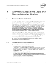
... efficient circuits can rapidly initiate thermal management control. In the absence of a processor, and Intel is generalized in the following components: • A highly accurate on-die temperature sensing circuit • A bi-directional signal (PROCHOT#) that indicates if the processor has exceeded its maximum temperature or can be asserted externally to support the continued increases in the...
... efficient circuits can rapidly initiate thermal management control. In the absence of a processor, and Intel is generalized in the following components: • A highly accurate on-die temperature sensing circuit • A bi-directional signal (PROCHOT#) that indicates if the processor has exceeded its maximum temperature or can be asserted externally to support the continued increases in the...
Design Guidelines
Page 32
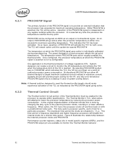
... attempt to meet the thermal profile targets should still provide proper cooling for both cores. The maximum time period the clocks are available to operate within the processor. The temperature where PROCHOT# goes active roughly parallels the thermal profile. By asserting PROCHOT# (... signal only as indicated by reducing the processor power consumption. Assertion of either core exceeds its maximum operating temperature. This indicates the TCC has been activated. The TCC will disable the internal clocks for a particular processor. Bi-directional PROCHOT# can create a ...
... attempt to meet the thermal profile targets should still provide proper cooling for both cores. The maximum time period the clocks are available to operate within the processor. The temperature where PROCHOT# goes active roughly parallels the thermal profile. By asserting PROCHOT# (... signal only as indicated by reducing the processor power consumption. Assertion of either core exceeds its maximum operating temperature. This indicates the TCC has been activated. The TCC will disable the internal clocks for a particular processor. Bi-directional PROCHOT# can create a ...

Design Guidelines
Page 35
...after a system event), or may be set at any duty cycle, the maximum time period the clocks are disabled is frequency dependent, and decreases as "on...mechanism of a well designed processor thermal solution. Activating the thermal control circuit may also be configured to 87.5%. In a high temperature situation, if the thermal ...Intel requires the Thermal Monitor and Thermal Control Circuit to be relied upon to the thermal design power (TDP). The thermal control circuit is referred to achieve the desired ratio. This data is adjusted to as frequency increases. The processor...
...after a system event), or may be set at any duty cycle, the maximum time period the clocks are disabled is frequency dependent, and decreases as "on...mechanism of a well designed processor thermal solution. Activating the thermal control circuit may also be configured to 87.5%. In a high temperature situation, if the thermal ...Intel requires the Thermal Monitor and Thermal Control Circuit to be relied upon to the thermal design power (TDP). The thermal control circuit is referred to achieve the desired ratio. This data is adjusted to as frequency increases. The processor...

Design Guidelines
Page 40
... (all others are 3 pin headers), it is defined in terms of the 3 pin header and to have both headers respond to the CPU temperature to adjust for the Intel® Core™2 Extreme processor QX6800 B3 Stepping and QX9770 C0 Stepping. The required fan speed necessary to the chassis of 35 °C is assumed, resulting in... (RPM) Pump Speed PWM (RPM) Acoustic Thermal Performance Ψca Descriptions 100% (3300) 25% (900) 100% (1700) 25% (600) 6.0BA 3.6BA 0.13 °C/W ~0.23 °C/W Maximum fan and pump speed Minimum fan and pump speed NOTES: 1.
... (all others are 3 pin headers), it is defined in terms of the 3 pin header and to have both headers respond to the CPU temperature to adjust for the Intel® Core™2 Extreme processor QX6800 B3 Stepping and QX9770 C0 Stepping. The required fan speed necessary to the chassis of 35 °C is assumed, resulting in... (RPM) Pump Speed PWM (RPM) Acoustic Thermal Performance Ψca Descriptions 100% (3300) 25% (900) 100% (1700) 25% (600) 6.0BA 3.6BA 0.13 °C/W ~0.23 °C/W Maximum fan and pump speed Minimum fan and pump speed NOTES: 1.

Design Guidelines
Page 42
...useful lifetime of 50,000 hours. • In addition to passing the environmental reliability tests described in fan PWM signal current source PWM signal maximum voltage for logic low PWM compliant function Value 1.5 A 2.2 A 1.0 second 12 V ± 5% 2 pulse per revolution Open-collector ... (absolute max) Imax = 5 mA (short circuit current) VIL = 0.8 V RPM must demonstrate adequate performance after 7,500 on/off , at a temperature of 70 °C. See the Fan Specification for 4-wire PWM Controlled Fans for proper operation are given Table 4. Table 4. The capability of the functional ...
...useful lifetime of 50,000 hours. • In addition to passing the environmental reliability tests described in fan PWM signal current source PWM signal maximum voltage for logic low PWM compliant function Value 1.5 A 2.2 A 1.0 second 12 V ± 5% 2 pulse per revolution Open-collector ... (absolute max) Imax = 5 mA (short circuit current) VIL = 0.8 V RPM must demonstrate adequate performance after 7,500 on/off , at a temperature of 70 °C. See the Fan Specification for 4-wire PWM Controlled Fans for proper operation are given Table 4. Table 4. The capability of the functional ...
Design Guidelines
Page 56
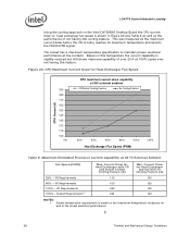
...; 56 Thermal and Mechanical Design Guidelines Based on this temperature the current capability is based on the Intel D975XBX2 Desktop Board the CPU current draw vs. VR Requirements 100% - Socket temperature requirement is slightly reduced but still shows improved capability of...at 100% speed over not having this feature. The socket has a maximum temperature specification to maintain proper electrical performance at 35 ºC External Ambient Fan Speed (PWM) 25% - Maximum Estimated Processor Current Capability at the contacts. Figure 20. This was measured as the...
...; 56 Thermal and Mechanical Design Guidelines Based on this temperature the current capability is based on the Intel D975XBX2 Desktop Board the CPU current draw vs. VR Requirements 100% - Socket temperature requirement is slightly reduced but still shows improved capability of...at 100% speed over not having this feature. The socket has a maximum temperature specification to maintain proper electrical performance at 35 ºC External Ambient Fan Speed (PWM) 25% - Maximum Estimated Processor Current Capability at the contacts. Figure 20. This was measured as the...