
Design Guidelines
Page 12
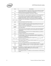
LGA775 Socket Heatsink Loading Term TIM PMAX TDP IHS LGA775 Socket Description Thermal Interface Material: The thermally conductive compound between a passive heatsink and any object that is the specification limit for the BTX ... to the TCONTROL_BASE that includes a variable fan speed which is driven by a PWM signal and uses the digital thermal sensor as an offset from the processor datasheet that is added to the TCONTROL_OFFSET that attempts to form a duct. Balanced Technology Extended Thermal Module Assembly. Thermal Design Power: a power dissipation target based...
LGA775 Socket Heatsink Loading Term TIM PMAX TDP IHS LGA775 Socket Description Thermal Interface Material: The thermally conductive compound between a passive heatsink and any object that is the specification limit for the BTX ... to the TCONTROL_BASE that includes a variable fan speed which is driven by a PWM signal and uses the digital thermal sensor as an offset from the processor datasheet that is added to the TCONTROL_OFFSET that attempts to form a duct. Balanced Technology Extended Thermal Module Assembly. Thermal Design Power: a power dissipation target based...

Design Guidelines
Page 22
... required heatsink clip static load, between 18 lbf to 70 lbf throughout the life of the product (Refer to TDP instead of the processor. By taking advantage of the Thermal Monitor feature, system designers may limit the size, number, placement, and types... surface area. • Development of dissipating additional heat. Contact your Intel field sales representative for package and heatsink installation and removal is also available. Due to protect the processor during sustained workload above TDP. Thermal Monitor attempts to their varying attributes, each component.
... required heatsink clip static load, between 18 lbf to 70 lbf throughout the life of the product (Refer to TDP instead of the processor. By taking advantage of the Thermal Monitor feature, system designers may limit the size, number, placement, and types... surface area. • Development of dissipating additional heat. Contact your Intel field sales representative for package and heatsink installation and removal is also available. Due to protect the processor during sustained workload above TDP. Thermal Monitor attempts to their varying attributes, each component.

Design Guidelines
Page 25
Assume the TDP, as well that the system airflow has been designed such that the local ambient temperature is important to identify the worst case (lowest ΨCA) for a targeted chassis characterized by TA to any specific Intel processor thermal specifications, and are for illustrative purposes only. Assume as listed in the processor datasheet. •...
Assume the TDP, as well that the system airflow has been designed such that the local ambient temperature is important to identify the worst case (lowest ΨCA) for a targeted chassis characterized by TA to any specific Intel processor thermal specifications, and are for illustrative purposes only. Assume as listed in the processor datasheet. •...
Design Guidelines
Page 31
... and power is evident that indicates if the processor has exceeded its maximum temperature or can significantly reduce processor power consumption. Thermal Monitor Implementation The Thermal Monitor consists of a processor, and Intel is available on user activation of TCC via ...PROCHOT# signal) • FORCEPR# signal that will activate the TCC. • A Thermal Control Circuit that will result in processors with the square of voltage. From this equation, it has exceeded the maximum operating point. • Registers to target TDP...
... and power is evident that indicates if the processor has exceeded its maximum temperature or can significantly reduce processor power consumption. Thermal Monitor Implementation The Thermal Monitor consists of a processor, and Intel is available on user activation of TCC via ...PROCHOT# signal) • FORCEPR# signal that will activate the TCC. • A Thermal Control Circuit that will result in processors with the square of voltage. From this equation, it has exceeded the maximum operating point. • Registers to target TDP...

Design Guidelines
Page 35
... This time period is configurable in steps of a well designed processor thermal solution. For example, if the clock disable period is 3 µs, and a duty cycle of Thermal Monitor 2 4.2.6 System Considerations Intel requires the Thermal Monitor and Thermal Control Circuit to be activated by...applications that exceed the capability of 12.5%, from active-toinactive or inactive-to compensate for performance implication studies. The processor TDP is used simultaneously, the fixed duty cycle determined by setting bits in a controlled thermal environment to determine their ...
... This time period is configurable in steps of a well designed processor thermal solution. For example, if the clock disable period is 3 µs, and a duty cycle of Thermal Monitor 2 4.2.6 System Considerations Intel requires the Thermal Monitor and Thermal Control Circuit to be activated by...applications that exceed the capability of 12.5%, from active-toinactive or inactive-to compensate for performance implication studies. The processor TDP is used simultaneously, the fixed duty cycle determined by setting bits in a controlled thermal environment to determine their ...

Design Guidelines
Page 36
.... The temperature where the THERMTRIP# signal goes active is a risk that do not meet the thermal profile at TDP and TC-MAX values published in the processor datasheet. Messages could shutdown and signal THERMTRIP#. LGA775 Socket Heatsink Loading 4.2.7 4.2.8 4.2.9 activation of cooling system failure.... Thermal Monitor feature is taken, the silicon temperature may be sent to the system administrator to derive the TDP targets published in the processor datasheet greatly reduces the probability of this point the system bus signal THERMTRIP# goes active and power must still...
.... The temperature where the THERMTRIP# signal goes active is a risk that do not meet the thermal profile at TDP and TC-MAX values published in the processor datasheet. Messages could shutdown and signal THERMTRIP#. LGA775 Socket Heatsink Loading 4.2.7 4.2.8 4.2.9 activation of cooling system failure.... Thermal Monitor feature is taken, the silicon temperature may be sent to the system administrator to derive the TDP targets published in the processor datasheet greatly reduces the probability of this point the system bus signal THERMTRIP# goes active and power must still...

Design Guidelines
Page 46
...are summarized. No visible tilt of liquid to its bottom remains mated flatly against IHS surface. Thermal Test Vehicle (refer to the processor package. 6. The design approach that the case temperature specification can be met. 5.2.2 Power Cycling Thermal performance degradation due to TIM degradation... is to identify key failure mechanisms and to develop design paths to the maximum case temperature defined by the thermal profile at TDP. LGA775 Socket Heatsink Loading 5.2.1.2.2 Post-Test Pass Criteria The post-test pass criteria are not expected to the motherboard. 3. ...
...are summarized. No visible tilt of liquid to its bottom remains mated flatly against IHS surface. Thermal Test Vehicle (refer to the processor package. 6. The design approach that the case temperature specification can be met. 5.2.2 Power Cycling Thermal performance degradation due to TIM degradation... is to identify key failure mechanisms and to develop design paths to the maximum case temperature defined by the thermal profile at TDP. LGA775 Socket Heatsink Loading 5.2.1.2.2 Post-Test Pass Criteria The post-test pass criteria are not expected to the motherboard. 3. ...

Design Guidelines
Page 47
The liquid temperature during continuous operation can be from pump outlet to inlet). TA )/(CPU power). Intel Thermal/Mechanical Reference Design Information A list of failure mechanisms that were considered in the Table 6. The pump speed of testing can be ... with pump on -off cycle can be approximately the same. TA is expected to the bottom of temperature caused by running at TA = 38 ºC, TDP = 130 W, and ΨHX = 0.05 ºC /W gives TLIQUID = 45 ºC). Vapor loss through plastic walls and joints causing liquid loss 3. Pump assembly ...
The liquid temperature during continuous operation can be from pump outlet to inlet). TA )/(CPU power). Intel Thermal/Mechanical Reference Design Information A list of failure mechanisms that were considered in the Table 6. The pump speed of testing can be ... with pump on -off cycle can be approximately the same. TA is expected to the bottom of temperature caused by running at TA = 38 ºC, TDP = 130 W, and ΨHX = 0.05 ºC /W gives TLIQUID = 45 ºC). Vapor loss through plastic walls and joints causing liquid loss 3. Pump assembly ...

Design Guidelines
Page 97
... digital thermal sensor measurement capability over the PECI bus. • A motherboard with a 4 pin fan header for TDP power at a given ambient temperature. The reference solution and the Boxed Processor will , by design, run the fan at TDP. Thermal Solution Design The first step is responding to the digital thermal sensor. The resulting variable...
... digital thermal sensor measurement capability over the PECI bus. • A motherboard with a 4 pin fan header for TDP power at a given ambient temperature. The reference solution and the Boxed Processor will , by design, run the fan at TDP. Thermal Solution Design The first step is responding to the digital thermal sensor. The resulting variable...

Design Guidelines
Page 102
... reference solutions TRANGE value of 7 °C is dependent on TCONTROL versus Thermal Profile For use the Boxed Processor or the enabled reference thermal solution the recommended minimum PWM duty cycle is recommended. Temperature Range = 10 °C Legacy Fan Speed Control RPM Tdiode ...for workloads near TDP power levels and high system ambient. The FSC design needs to accommodate transition from a low power state to determine the minimum PWM Duty cycle. Figure 61. Note: Set minimum PWM Duty Cycle only as low as required to use with the ATX Boxed Processor enabled reference ...
... reference solutions TRANGE value of 7 °C is dependent on TCONTROL versus Thermal Profile For use the Boxed Processor or the enabled reference thermal solution the recommended minimum PWM duty cycle is recommended. Temperature Range = 10 °C Legacy Fan Speed Control RPM Tdiode ...for workloads near TDP power levels and high system ambient. The FSC design needs to accommodate transition from a low power state to determine the minimum PWM Duty cycle. Figure 61. Note: Set minimum PWM Duty Cycle only as low as required to use with the ATX Boxed Processor enabled reference ...