

Design Guidelines
Page 3
...19 2.1.2.2 Heatsink Clip Load Requirement 19 2.1.2.3 Additional Guidelines 20 2.2 Thermal Requirements 20 2.2.1 Processor Case Temperature 20 2.2.2 Thermal Profile 21 2.2.3 TCONTROL 23 2.3 Heatsink Design Considerations 24 2.3.1 Heatsink Size ... Requirements 29 3.1.1 Example 31 3.2 Processor Thermal Solution Performance Assessment 31 3.3 Local Ambient Temperature Measurement Guidelines 32 3.4 Processor Case Temperature Measurement Guidelines 34 4 Thermal Management Logic and Thermal Monitor Feature 35 4.1 Processor Power Dissipation 35 4.2 Thermal Monitor Implementation...
...19 2.1.2.2 Heatsink Clip Load Requirement 19 2.1.2.3 Additional Guidelines 20 2.2 Thermal Requirements 20 2.2.1 Processor Case Temperature 20 2.2.2 Thermal Profile 21 2.2.3 TCONTROL 23 2.3 Heatsink Design Considerations 24 2.3.1 Heatsink Size ... Requirements 29 3.1.1 Example 31 3.2 Processor Thermal Solution Performance Assessment 31 3.3 Local Ambient Temperature Measurement Guidelines 32 3.4 Processor Case Temperature Measurement Guidelines 34 4 Thermal Management Logic and Thermal Monitor Feature 35 4.1 Processor Power Dissipation 35 4.2 Thermal Monitor Implementation...

Design Guidelines
Page 5
...Preload Degradation under Bake Conditions 73 Thermal Interface Management 75 C.1 Bond Line Management 75 C.2 Interface Material Area 75 C.3 Interface Material Performance 75 Case Temperature Reference Metrology 77 D.1 Objective and Scope 77 D.2 Supporting Test Equipment 77 D.3 Thermal calibration and controls 78 D.4 IHS Groove 79 D.5 Thermocouple Attach... 96 Balanced Technology Extended (BTX) System Thermal Considerations 99 Appendix F Mechanical Drawings 103 Appendix G Intel® Enabled Reference Solution Information 123 Thermal and Mechanical Design Guidelines 5
...Preload Degradation under Bake Conditions 73 Thermal Interface Management 75 C.1 Bond Line Management 75 C.2 Interface Material Area 75 C.3 Interface Material Performance 75 Case Temperature Reference Metrology 77 D.1 Objective and Scope 77 D.2 Supporting Test Equipment 77 D.3 Thermal calibration and controls 78 D.4 IHS Groove 79 D.5 Thermocouple Attach... 96 Balanced Technology Extended (BTX) System Thermal Considerations 99 Appendix F Mechanical Drawings 103 Appendix G Intel® Enabled Reference Solution Information 123 Thermal and Mechanical Design Guidelines 5
Design Guidelines
Page 6
...Figure 9. TCONTROL for Interfacing to the LGA775 Socket ...83 Figure 34. Exploded View 43 Figure 11. Critical Core Dimension 55 Figure 19. Example Acoustic Fan Speed Control Implementation 61 Figure 23. Load Cell Installation in Machined Heatsink...Load Areas 17 Figure 2. Processor Case Temperature Measurement Location 21 Figure 3. Locations for Measuring Local Ambient Temperature, Passive Heatsink ......33 Figure 7. Locations for Measuring Local Ambient Temperature, Active Heatsink ........33 Figure 6. Intel® RCFH-4 Reference Design - Intel D60188-001 Reference Design ...
...Figure 9. TCONTROL for Interfacing to the LGA775 Socket ...83 Figure 34. Exploded View 43 Figure 11. Critical Core Dimension 55 Figure 19. Example Acoustic Fan Speed Control Implementation 61 Figure 23. Load Cell Installation in Machined Heatsink...Load Areas 17 Figure 2. Processor Case Temperature Measurement Location 21 Figure 3. Locations for Measuring Local Ambient Temperature, Passive Heatsink ......33 Figure 7. Locations for Measuring Local Ambient Temperature, Active Heatsink ........33 Figure 6. Intel® RCFH-4 Reference Design - Intel D60188-001 Reference Design ...

Design Guidelines
Page 8
Fan Electrical Performance Requirements 48 Table 8. Heatsink Inlet Temperature of Intel® Boxed Processor thermal solutions .....27 Table 3. RCFH-4 Reference Thermal Solution Providers 123 Table 12. Heatsink Inlet Temperature of Intel Reference Thermal Solutions 27 Table 2. ATX Reference Heatsink Performance (RCFH-4) for ATX Reference Heatsink (D60188-001 46 Table 7. Tables Table 1. Acoustic Results for 775_VR_CONFIG 05B...
Fan Electrical Performance Requirements 48 Table 8. Heatsink Inlet Temperature of Intel® Boxed Processor thermal solutions .....27 Table 3. RCFH-4 Reference Thermal Solution Providers 123 Table 12. Heatsink Inlet Temperature of Intel Reference Thermal Solutions 27 Table 2. ATX Reference Heatsink Performance (RCFH-4) for ATX Reference Heatsink (D60188-001 46 Table 7. Tables Table 1. Acoustic Results for 775_VR_CONFIG 05B...
Design Guidelines
Page 11
... air temperature and airflow over the processor as well as the physical constraints at and above the processor. The system level thermal constraints consist of both system and component thermal characteristics. The result is an increased importance on single processor systems using the Intel® Core™2 Extreme quad-core processor QX6000 series, Intel® Core™2 Quad processor Q6000 series, Intel® Core™2 Quad processor...
... air temperature and airflow over the processor as well as the physical constraints at and above the processor. The system level thermal constraints consist of both system and component thermal characteristics. The result is an increased importance on single processor systems using the Intel® Core™2 Extreme quad-core processor QX6000 series, Intel® Core™2 Quad processor Q6000 series, Intel® Core™2 Quad processor...
Design Guidelines
Page 13
... Processor QX9000 Series and Intel® Core™2 Quad Processor Q9000, Q9000S, Q8000, and Q8000SSeries Datasheet Intel® Core™2 Duo Processor E8000 and E7000 Series and Intel® Pentium® Dual-Core Processor E5000 Series Thermal and Mechanical Design Guide LGA775 Socket Mechanical Design Guide Fan Specification for the product dimensions, thermal power dissipation and maximum case temperature...
... Processor QX9000 Series and Intel® Core™2 Quad Processor Q9000, Q9000S, Q8000, and Q8000SSeries Datasheet Intel® Core™2 Duo Processor E8000 and E7000 Series and Intel® Pentium® Dual-Core Processor E5000 Series Thermal and Mechanical Design Guide LGA775 Socket Mechanical Design Guide Fan Specification for the product dimensions, thermal power dissipation and maximum case temperature...
Design Guidelines
Page 14
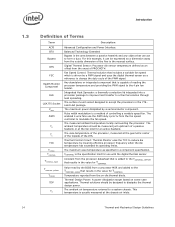
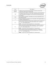
...fan speed which is capable of reading the processor temperature and providing the PWM signal to change the duty cycle of the PWM signal. The case temperature of the IHS. Constant from the processor datasheet that is the specification limit for ...designed to dissipate the thermal design power. The measured ambient temperature locally surrounding the processor. The ambient air temperature external to reduce die temperature by a semiconductor component. Digital Thermal Sensor: Processor die sensor temperature defined as specified in a component specification. Thermal Control ...
...fan speed which is capable of reading the processor temperature and providing the PWM signal to change the duty cycle of the PWM signal. The case temperature of the IHS. Constant from the processor datasheet that is the specification limit for ...designed to dissipate the thermal design power. The measured ambient temperature locally surrounding the processor. The ambient air temperature external to reduce die temperature by a semiconductor component. Digital Thermal Sensor: Processor die sensor temperature defined as specified in a component specification. Thermal Control ...
Design Guidelines
Page 15
... for measurements. Case-to TC. NOTE: Heat source must be specified for the BTX thermal solution Heatsink temperature measured on the processor that attempts to -ambient thermal characterization parameter (psi). A measure of heatsink thermal performance using total package power. Thermal... fills the air gaps and voids, and enhances the transfer of the heat from the processor case to -ambient thermal characterization parameter. Case-to keep the processor die temperature within factory specifications. NOTE: Heat source must be specified for measurements. Defined ...
... for measurements. Case-to TC. NOTE: Heat source must be specified for the BTX thermal solution Heatsink temperature measured on the processor that attempts to -ambient thermal characterization parameter (psi). A measure of heatsink thermal performance using total package power. Thermal... fills the air gaps and voids, and enhances the transfer of the heat from the processor case to -ambient thermal characterization parameter. Case-to keep the processor die temperature within factory specifications. NOTE: Heat source must be specified for measurements. Defined ...
Design Guidelines
Page 19
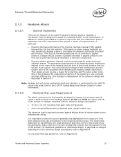
... the pressure, the better the initial performance. Their design should provide a means for mechanical protection of socket solder joint in temperature cycling. Note: Package pull-out during mechanical shock and vibration is to the required minimum load. The minimum load is implemented...Socket Mechanical Design Guide for further information). 2.1.2.2 Heatsink Clip Load Requirement The attach mechanism for the heatsink developed to support the processor should consider a possible decrease in applied pressure over time when designing the clip and fastener to use a preload and high ...
... the pressure, the better the initial performance. Their design should provide a means for mechanical protection of socket solder joint in temperature cycling. Note: Package pull-out during mechanical shock and vibration is to the required minimum load. The minimum load is implemented...Socket Mechanical Design Guide for further information). 2.1.2.2 Heatsink Clip Load Requirement The attach mechanism for the heatsink developed to support the processor should consider a possible decrease in applied pressure over time when designing the clip and fastener to use a preload and high ...

Design Guidelines
Page 20
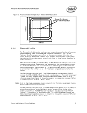
...of special tools. The thermal limits for processor performance and acoustic noise reduction. 2.2.1 Processor Case Temperature For the processor, the case temperature is a specification used in conjunction with a 28.7 mm x 28.7 mm [1.13 in x 1.13 in the corresponding processor datasheet. Engages easily, and ... shows the measurement location for a 37.5 mm x 37.5 mm [1.474 in x 1.474 in] 775-Land LGA processor package with the temperature reported by the heatsink attach mechanism must comply with its tolerances The height of the package, from the package ...
...of special tools. The thermal limits for processor performance and acoustic noise reduction. 2.2.1 Processor Case Temperature For the processor, the case temperature is a specification used in conjunction with a 28.7 mm x 28.7 mm [1.13 in x 1.13 in the corresponding processor datasheet. Engages easily, and ... shows the measurement location for a 37.5 mm x 37.5 mm [1.474 in x 1.474 in] 775-Land LGA processor package with the temperature reported by the heatsink attach mechanism must comply with its tolerances The height of the package, from the package ...
Design Guidelines
Page 21
... will have up to a 35 °C ambient temperature external to the processor datasheet for Thermally Advantaged Chassis thermal and mechanical requirements. While the thermal profile provides flexibility for the worst-case thermal environment. Refer to the system. For ATX platforms using the Intel® Core™2 Quad processor Q6000 series at 105 W, an active air-cooled...
... will have up to a 35 °C ambient temperature external to the processor datasheet for Thermally Advantaged Chassis thermal and mechanical requirements. While the thermal profile provides flexibility for the worst-case thermal environment. Refer to the system. For ATX platforms using the Intel® Core™2 Quad processor Q6000 series at 105 W, an active air-cooled...
Design Guidelines
Page 22
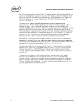
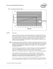
... profile. 22 Thermal and Mechanical Design Guidelines Processor Thermal/Mechanical Information For ATX platforms using the Intel® Core™2 Quad processor Q6000 series at 95 W, an active air-cooled design, assumed be used for the Intel® Core™2 Extreme quad-core processor QX6000 series at the 775_VR_CONFIG_05B dissipating 110 W the maximum case temperature is 61.1 °C. The intercept on...
... profile. 22 Thermal and Mechanical Design Guidelines Processor Thermal/Mechanical Information For ATX platforms using the Intel® Core™2 Quad processor Q6000 series at 95 W, an active air-cooled design, assumed be used for the Intel® Core™2 Extreme quad-core processor QX6000 series at the 775_VR_CONFIG_05B dissipating 110 W the maximum case temperature is 61.1 °C. The intercept on...
Design Guidelines
Page 23
... for the discussion of these is driven by the system BIOS based on Intel® Quiet System Technology (Intel® QST). Example Thermal Profile 2.2.3 TCONTROL TCONTROL defines the maximum operating temperature for the digital thermal sensor when the thermal solution fan speed is achieved... Thermal Control Circuit (TCC) activation set point which will dissipate more negative number) of factors. See Chapter 4 for the processor is calculated by a number of TCONTROL when running the same application. A thermal solution designed to meet the thermal profile would be...
... for the discussion of these is driven by the system BIOS based on Intel® Quiet System Technology (Intel® QST). Example Thermal Profile 2.2.3 TCONTROL TCONTROL defines the maximum operating temperature for the digital thermal sensor when the thermal solution fan speed is achieved... Thermal Control Circuit (TCC) activation set point which will dissipate more negative number) of factors. See Chapter 4 for the processor is calculated by a number of TCONTROL when running the same application. A thermal solution designed to meet the thermal profile would be...
Design Guidelines
Page 24
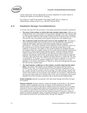
...controlling airflow through it . The nature of the airflow can increase the effective heat transfer surface area by the local ambient temperature of the processor package IHS. These heatsinks are therefore typically larger (and heavier) than active heatsinks due to the increase in fin surface ...required to the IHS. See Chapter 6 Intel® Quiet System Technology (Intel® QST) for further information on TIM and on bond line management...
...controlling airflow through it . The nature of the airflow can increase the effective heat transfer surface area by the local ambient temperature of the processor package IHS. These heatsinks are therefore typically larger (and heavier) than active heatsinks due to the increase in fin surface ...required to the IHS. See Chapter 6 Intel® Quiet System Technology (Intel® QST) for further information on TIM and on bond line management...

Design Guidelines
Page 27
... that the chassis delivers a maximum TA at the 775_VR_CONFIG_05B, Intel® Core™2 Quad processor Q6000 series, Intel® Core™2 Extreme processor QX9000 series, and Intel® Core™2 Quad processor Q9000 and Q8000series Heatsink Inlet Temperature 39 °C NOTE: 1. Boxed Processor thermal solutions for the reference solutions and Intel® Boxed Processor thermal solutions. Additional constraints are assumed be removed to...
... that the chassis delivers a maximum TA at the 775_VR_CONFIG_05B, Intel® Core™2 Quad processor Q6000 series, Intel® Core™2 Extreme processor QX9000 series, and Intel® Core™2 Quad processor Q9000 and Q8000series Heatsink Inlet Temperature 39 °C NOTE: 1. Boxed Processor thermal solutions for the reference solutions and Intel® Boxed Processor thermal solutions. Additional constraints are assumed be removed to...
Design Guidelines
Page 28
...and roughness. The performance of the thermal interface material used in heatsink design include: The local ambient temperature TA at the entire system level, accounting for all capable of CA is the System Assembly module. Summary In summary... area. Physical volumetric constraints placed by designing to protect the processor during sustained workload above TDP. Thermal Monitor attempts to TDP instead of the processor. Contact your Intel field sales representative for a particular system implementation. Due to air thermal characterization...
...and roughness. The performance of the thermal interface material used in heatsink design include: The local ambient temperature TA at the entire system level, accounting for all capable of CA is the System Assembly module. Summary In summary... area. Physical volumetric constraints placed by designing to protect the processor during sustained workload above TDP. Thermal Monitor attempts to TDP instead of the processor. Contact your Intel field sales representative for a particular system implementation. Due to air thermal characterization...
Design Guidelines
Page 29
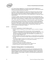
... characterization parameter is a convenient way to characterize the performance needed for testing thermal solutions, including measuring processor temperatures. Note: Heat transfer is a three-dimensional phenomenon that is attached to validate a thermal solution. It... guidelines for the thermal solution and to -local ambient thermal characterization parameter (°C/W) = Processor case temperature (°C) = Local ambient temperature in chassis at processor (°C) = Processor total power dissipation (W) (assumes all cases, the thermal engineer must measure power dissipation and...
... characterization parameter is a convenient way to characterize the performance needed for testing thermal solutions, including measuring processor temperatures. Note: Heat transfer is a three-dimensional phenomenon that is attached to validate a thermal solution. It... guidelines for the thermal solution and to -local ambient thermal characterization parameter (°C/W) = Processor case temperature (°C) = Local ambient temperature in chassis at processor (°C) = Processor total power dissipation (W) (assumes all cases, the thermal engineer must measure power dissipation and...
Design Guidelines
Page 31
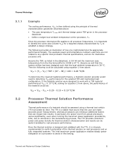
... in this testing. If the heatsink solution were designed to any specific Intel processor thermal specifications, and are for equation 2 from above : CA = (TC,- The example power and temperature numbers used here are not related to work with the TTV, it ...defined using the principle of the thermal solution on real processors and on fully integrated systems. The Intel maximum power application enables steady power dissipation on a processor to variances in the processor datasheet. Define a target local ambient temperature at CS 0.10 °C/W, solving...
... in this testing. If the heatsink solution were designed to any specific Intel processor thermal specifications, and are for equation 2 from above : CA = (TC,- The example power and temperature numbers used here are not related to work with the TTV, it ...defined using the principle of the thermal solution on real processors and on fully integrated systems. The Intel maximum power application enables steady power dissipation on a processor to variances in the processor datasheet. Define a target local ambient temperature at CS 0.10 °C/W, solving...

Design Guidelines
Page 32
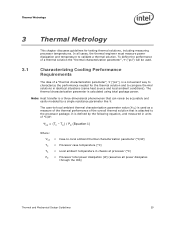
... ] above the fan hub vertically and halfway between the fan hub and the fan housing. This placement guideline is the temperature of the ambient air surrounding the processor. Note: Testing an active heatsink with a clear tape at multiple locations in ]. It is typically clear Plexiglas*, extending ... above the location of the chassis. For active heatsinks, it is important to enable accurate determination of the localized air temperature around the processor to understand the effect it is then necessary to disable the fan regulation and power the fan directly, based on the case...
... ] above the fan hub vertically and halfway between the fan hub and the fan housing. This placement guideline is the temperature of the ambient air surrounding the processor. Note: Testing an active heatsink with a clear tape at multiple locations in ]. It is typically clear Plexiglas*, extending ... above the location of the chassis. For active heatsinks, it is important to enable accurate determination of the localized air temperature around the processor to understand the effect it is then necessary to disable the fan regulation and power the fan directly, based on the case...
Design Guidelines
Page 33
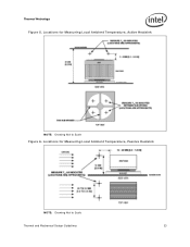
Thermal Metrology Figure 5. Locations for Measuring Local Ambient Temperature, Passive Heatsink NOTE: Drawing Not to Scale Figure 6. Locations for Measuring Local Ambient Temperature, Active Heatsink NOTE: Drawing Not to Scale Thermal and Mechanical Design Guidelines 33
Thermal Metrology Figure 5. Locations for Measuring Local Ambient Temperature, Passive Heatsink NOTE: Drawing Not to Scale Figure 6. Locations for Measuring Local Ambient Temperature, Active Heatsink NOTE: Drawing Not to Scale Thermal and Mechanical Design Guidelines 33
