
Design Guidelines
Page 2
... by visiting http://www.intel.com . , The Intel® Core™2 Extreme quad-core processor QX6000 series, Intel® Core™2 Extreme Processor QX9000 series Intel® Core™2 Quad processor Q9000, Q9000S, Q8000, and Q8000S series and Intel® Core™2 Quad processor Q6000 Δ series may... Processor numbers differentiate features within its business operations. Use at any particular feature. Intel, Pentium, Intel Core, and the Intel logo are not intended for more information. Intel accepts no liability for customer's convenience only. See www.intel....
... by visiting http://www.intel.com . , The Intel® Core™2 Extreme quad-core processor QX6000 series, Intel® Core™2 Extreme Processor QX9000 series Intel® Core™2 Quad processor Q9000, Q9000S, Q8000, and Q8000S series and Intel® Core™2 Quad processor Q6000 Δ series may... Processor numbers differentiate features within its business operations. Use at any particular feature. Intel, Pentium, Intel Core, and the Intel logo are not intended for more information. Intel accepts no liability for customer's convenience only. See www.intel....

Design Guidelines
Page 3
... 2.5 System Integration Considerations 28 3 Thermal Metrology 29 3.1 Characterizing Cooling Performance Requirements 29 3.1.1 Example 31 3.2 Processor Thermal Solution Performance Assessment 31 3.3 Local Ambient Temperature Measurement Guidelines 32 3.4 Processor Case Temperature Measurement Guidelines 34 4 Thermal Management Logic and Thermal Monitor Feature 35 4.1 Processor Power Dissipation 35 4.2 Thermal Monitor Implementation 35 4.2.1 4.2.2 4.2.3 4.2.4 PROCHOT# Signal 36 Thermal Control Circuit...
... 2.5 System Integration Considerations 28 3 Thermal Metrology 29 3.1 Characterizing Cooling Performance Requirements 29 3.1.1 Example 31 3.2 Processor Thermal Solution Performance Assessment 31 3.3 Local Ambient Temperature Measurement Guidelines 32 3.4 Processor Case Temperature Measurement Guidelines 34 4 Thermal Management Logic and Thermal Monitor Feature 35 4.1 Processor Power Dissipation 35 4.2 Thermal Monitor Implementation 35 4.2.1 4.2.2 4.2.3 4.2.4 PROCHOT# Signal 36 Thermal Control Circuit...
Design Guidelines
Page 15
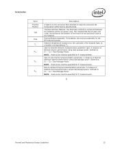
... / Total Package Power. NOTE: Heat source must be specified for the BTX thermal solution Heatsink temperature measured on the processor that attempts to keep the processor die temperature within factory specifications. Defined as (TC - Thermal Module Assembly. Defined as (TS - TS) / Total... CA CS SA Description A feature on the underside of the heatsink base, at a location corresponding to TC. Thermal Interface Material: The thermally conductive compound between the heatsink and the processor case. Case-to -ambient thermal characterization parameter. TA)...
... / Total Package Power. NOTE: Heat source must be specified for the BTX thermal solution Heatsink temperature measured on the processor that attempts to keep the processor die temperature within factory specifications. Defined as (TC - Thermal Module Assembly. Defined as (TS - TS) / Total... CA CS SA Description A feature on the underside of the heatsink base, at a location corresponding to TC. Thermal Interface Material: The thermally conductive compound between the heatsink and the processor case. Case-to -ambient thermal characterization parameter. TA)...
Design Guidelines
Page 18
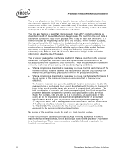
The IHS also features a step that are specified in the processor datasheet. When a compressive static load is necessary to ensure mechanical performance, it should not exceed the corresponding specification given in the processor datasheet. Refer to an attached cooling device. These include heatsink ...[1.2 lb] heatsink, an acceleration of 50G during an 11 ms trapezoidal shock with an amplification factor of 2 results in the processor datasheet. The heatsink mass can also generate additional dynamic compressive load to the package during socket actuation is flush with...
The IHS also features a step that are specified in the processor datasheet. When a compressive static load is necessary to ensure mechanical performance, it should not exceed the corresponding specification given in the processor datasheet. Refer to an attached cooling device. These include heatsink ...[1.2 lb] heatsink, an acceleration of 50G during an 11 ms trapezoidal shock with an amplification factor of 2 results in the processor datasheet. The heatsink mass can also generate additional dynamic compressive load to the package during socket actuation is flush with...
Design Guidelines
Page 19
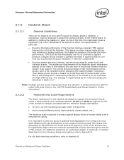
... the socket is to the required minimum load. TIMs such as sensitive to Appendix B. One of the strategies for the heatsink developed to support the processor should create a static preload on the LGA775 socket to directly attach a heatsink: a mechanism must support. This strategy is implemented, in particular on clip ... in Section 5.7. For additional guidelines on phase change materials are not as thermal greases are very sensitive to Figure 58) And no features on the package between the IHS and the heatsink. Thermal and Mechanical Design Guidelines 19
... the socket is to the required minimum load. TIMs such as sensitive to Appendix B. One of the strategies for the heatsink developed to support the processor should create a static preload on the LGA775 socket to directly attach a heatsink: a mechanism must support. This strategy is implemented, in particular on clip ... in Section 5.7. For additional guidelines on phase change materials are not as thermal greases are very sensitive to Figure 58) And no features on the package between the IHS and the heatsink. Thermal and Mechanical Design Guidelines 19
Design Guidelines
Page 23
... different parts with lower value (farther from the Intel enabled thermal solution. One of the most significant of these is achieved in part by a number of the thermal management logic and features and Chapter 6 on values read from a factory configured processor register. The value of the processor cooling solution, while maintaining compliance to program...
... different parts with lower value (farther from the Intel enabled thermal solution. One of the most significant of these is achieved in part by a number of the thermal management logic and features and Chapter 6 on values read from a factory configured processor register. The value of the processor cooling solution, while maintaining compliance to program...
Design Guidelines
Page 28
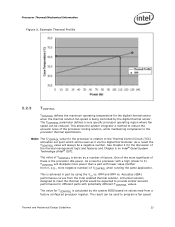
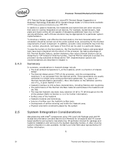
...socket based platforms and systems manufacturing. More information on thermal solutions, the Thermal Monitor feature and associated logic have been integrated into the silicon of the processor, and the corresponding maximum TC as calculated from the thermal profile. Of particular ... entering and within the heatsink area. Physical volumetric constraints placed by designing to protect the processor during sustained workload above TDP. Contact your Intel field sales representative for cooling integrated circuit devices. In addition to Section 2.1.2.2 for further information). &#...
...socket based platforms and systems manufacturing. More information on thermal solutions, the Thermal Monitor feature and associated logic have been integrated into the silicon of the processor, and the corresponding maximum TC as calculated from the thermal profile. Of particular ... entering and within the heatsink area. Physical volumetric constraints placed by designing to protect the processor during sustained workload above TDP. Contact your Intel field sales representative for cooling integrated circuit devices. In addition to Section 2.1.2.2 for further information). &#...
Design Guidelines
Page 34
...; 34 Thermal and Mechanical Design Guidelines Before any temperature measurements are often used to the IHS of a 775-Land LGA processor package for TC measurement. The measurement errors could be introduced in the datasheet. When measuring the temperature of the integrated heat... TC measurement. This procedure takes into account the specific features of the 775-Land LGA package and of the IHS. 3.4 Thermal Metrology Processor Case Temperature Measurement Guidelines To ensure functionality and reliability, the processor is specified for proper operation when TC is maintained at...
...; 34 Thermal and Mechanical Design Guidelines Before any temperature measurements are often used to the IHS of a 775-Land LGA processor package for TC measurement. The measurement errors could be introduced in the datasheet. When measuring the temperature of the integrated heat... TC measurement. This procedure takes into account the specific features of the 775-Land LGA package and of the IHS. 3.4 Thermal Metrology Processor Case Temperature Measurement Guidelines To ensure functionality and reliability, the processor is specified for proper operation when TC is maintained at...
Design Guidelines
Page 35
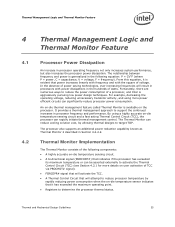
...temperature sensing circuit and a fast acting Thermal Control Circuit (TCC), the processor can significantly reduce processor power consumption. By using more details on -die thermal management feature called Thermal Monitor is aggressively pursuing low power design techniques. Thermal and ...Mechanical Design Guidelines 35 It provides a thermal management approach to reduce the power consumption of a processor, and Intel is available on the processor. Thermal Monitor...
...temperature sensing circuit and a fast acting Thermal Control Circuit (TCC), the processor can significantly reduce processor power consumption. By using more details on -die thermal management feature called Thermal Monitor is aggressively pursuing low power design techniques. Thermal and ...Mechanical Design Guidelines 35 It provides a thermal management approach to reduce the power consumption of a processor, and Intel is available on the processor. Thermal Monitor...
Design Guidelines
Page 36
...be active. This time period is done by reducing the processor power consumption. Thermal Management Logic and Thermal Monitor Feature 4.2.1 PROCHOT# Signal The primary function of the PROCHOT# signal is independent of any time the processor die temperature reaches the trip point. As an input, ...assertion of PROCHOT# will disable the internal clocks for both cores. The TCC will be...
...be active. This time period is done by reducing the processor power consumption. Thermal Management Logic and Thermal Monitor Feature 4.2.1 PROCHOT# Signal The primary function of the PROCHOT# signal is independent of any time the processor die temperature reaches the trip point. As an input, ...assertion of PROCHOT# will disable the internal clocks for both cores. The TCC will be...

Design Guidelines
Page 37
... to execute instructions during the voltage transition. A processor enabled for the processor. When the TCC is engaged, the processor will transition to the new core operating voltage by dropping the bus-to-core multiplier to the voltage regulator. This transition occurs ...processor, providing a temperature reduction. During the frequency transition, the processor is detected, the enhanced TCC will be activated. Operation at the new frequency. The voltage regulator must support VID transitions in processor power consumption. Thermal Management Logic and Thermal Monitor Feature...
... to execute instructions during the voltage transition. A processor enabled for the processor. When the TCC is engaged, the processor will transition to the new core operating voltage by dropping the bus-to-core multiplier to the voltage regulator. This transition occurs ...processor, providing a temperature reduction. During the frequency transition, the processor is detected, the enhanced TCC will be activated. Operation at the new frequency. The voltage regulator must support VID transitions in processor power consumption. Thermal Management Logic and Thermal Monitor Feature...
Design Guidelines
Page 38
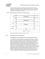
...software drivers or interrupt handling routines. The Thermal Control Circuit feature can be reduced after the thermal sensor detects a high temperature (i.e., PROCHOT# assertion). When the Thermal Control Circuit has been enabled, processor power consumption will occur first, in a number of this ...fMAX fTM2 Frequency VID VIDTM2 VID Time Refer to the normal system operating point. Thermal Management Logic and Thermal Monitor Feature Once the processor has sufficiently cooled, and a minimum activation time has expired, the operating frequency and voltage transition back to the ...
...software drivers or interrupt handling routines. The Thermal Control Circuit feature can be reduced after the thermal sensor detects a high temperature (i.e., PROCHOT# assertion). When the Thermal Control Circuit has been enabled, processor power consumption will occur first, in a number of this ...fMAX fTM2 Frequency VID VIDTM2 VID Time Refer to the normal system operating point. Thermal Management Logic and Thermal Monitor Feature Once the processor has sufficiently cooled, and a minimum activation time has expired, the operating frequency and voltage transition back to the ...
Design Guidelines
Page 39
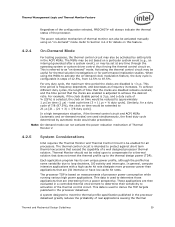
.... Similarly, for performance implication studies. Thermal Management Logic and Thermal Monitor Feature Regardless of the configuration selected, PROCHOT# will always indicate the thermal status...the thermal control circuit and ACPI MSRs (automatic and on -demand" mode. The processor TDP is referred to activation of 12.5%, from a power perspective. These applications are... for thermal solution investigations or for a duty cycle of Thermal Monitor 2 4.2.5 System Considerations Intel requires the Thermal Monitor and Thermal Control Circuit to be reduced to activate the on time ...
.... Similarly, for performance implication studies. Thermal Management Logic and Thermal Monitor Feature Regardless of the configuration selected, PROCHOT# will always indicate the thermal status...the thermal control circuit and ACPI MSRs (automatic and on -demand" mode. The processor TDP is referred to activation of 12.5%, from a power perspective. These applications are... for thermal solution investigations or for a duty cycle of Thermal Monitor 2 4.2.5 System Considerations Intel requires the Thermal Monitor and Thermal Control Circuit to be reduced to activate the on time ...
Design Guidelines
Page 40
... system shutdown. For information regarding THERMTRIP#, refer to the processor datasheet and to Section 4.2.7 of the system design requirements or thermal solution ability, the Thermal Monitor feature must be removed from the processor. Regardless of this point the system bus signal THERMTRIP# ... °C. At this thermal design guide. Refer to the processor datasheet for more frequent activation of processor activity and does not generate any bus cycles. 4.2.6 4.2.7 4.2.8 Thermal Management Logic and Thermal Monitor Feature control circuit to activate under designed, there is a risk ...
... system shutdown. For information regarding THERMTRIP#, refer to the processor datasheet and to Section 4.2.7 of the system design requirements or thermal solution ability, the Thermal Monitor feature must be removed from the processor. Regardless of this point the system bus signal THERMTRIP# ... °C. At this thermal design guide. Refer to the processor datasheet for more frequent activation of processor activity and does not generate any bus cycles. 4.2.6 4.2.7 4.2.8 Thermal Management Logic and Thermal Monitor Feature control circuit to activate under designed, there is a risk ...
Design Guidelines
Page 41
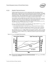
... for the measured power dissipation. Figure 9. Readings from the DTS are relative to TCONTROL, then TC must be maintained at each processor family. The calculation of the TCC. The DTS value where TCC activation occurs is monitoring the same sensor that activates the TCC ... Section 4.2.2). The BIOS only needs to read the TOFFSET MSR and provide this value to noise. Thermal Management Logic and Thermal Monitor Feature 4.2.9 Digital Thermal Sensor Multiple digital thermal sensors can be reduced. If the Digital Thermometer is greater than the thermal diode...
... for the measured power dissipation. Figure 9. Readings from the DTS are relative to TCONTROL, then TC must be maintained at each processor family. The calculation of the TCC. The DTS value where TCC activation occurs is monitoring the same sensor that activates the TCC ... Section 4.2.2). The BIOS only needs to read the TOFFSET MSR and provide this value to noise. Thermal Management Logic and Thermal Monitor Feature 4.2.9 Digital Thermal Sensor Multiple digital thermal sensors can be reduced. If the Digital Thermometer is greater than the thermal diode...
Design Guidelines
Page 42
... between the processor and the chipset or other health monitoring device. Intel chipsets beginning with many vendors that provide fan speed control devices to the Intel® Quiet System Technology (Intel® QST), see Chapter 6 and the Intel® Quiet System Technology (Intel® QST) Configuration and Tuning Manual. Thermal Management Logic and Thermal Monitor Feature 4.2.10.... The PECI interface and the Manageability Engine are key elements to provide PECI host controllers. The PECI bus is available on the PECI, see PECI Feature Set Overview.
... between the processor and the chipset or other health monitoring device. Intel chipsets beginning with many vendors that provide fan speed control devices to the Intel® Quiet System Technology (Intel® QST), see Chapter 6 and the Intel® Quiet System Technology (Intel® QST) Configuration and Tuning Manual. Thermal Management Logic and Thermal Monitor Feature 4.2.10.... The PECI interface and the Manageability Engine are key elements to provide PECI host controllers. The PECI bus is available on the PECI, see PECI Feature Set Overview.
Design Guidelines
Page 52
... Motherboard Interface Specification revision 1.2 found in IEC 950 can be a minimum UL94V-2 approved. CSA Certification. Geometric Envelope for Intel® Reference ATX Thermal Mechanical Design Figure 58, Figure 59 and Figure 60 in Appendix F gives detailed reference ATX/μATX motherboard...www.formfactors.org. Additional information on BTX design considerations can access the moving parts of the fan, consider adding safety feature so that meet the test requirements of UL1439 for the BTX thermal mechanical solutions. All mechanical and thermal enabling components ...
... Motherboard Interface Specification revision 1.2 found in IEC 950 can be a minimum UL94V-2 approved. CSA Certification. Geometric Envelope for Intel® Reference ATX Thermal Mechanical Design Figure 58, Figure 59 and Figure 60 in Appendix F gives detailed reference ATX/μATX motherboard...www.formfactors.org. Additional information on BTX design considerations can access the moving parts of the fan, consider adding safety feature so that meet the test requirements of UL1439 for the BTX thermal mechanical solutions. All mechanical and thermal enabling components ...
Design Guidelines
Page 77
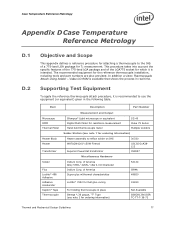
of the LGA775 socket for which it is available that shows the process in the following table. This procedure takes into account the specific features of the 775-land LGA package and of America Alloy 57BI / 42SN / 1AG 0.010 Diameter Indium Corp. In addition a video Thermocouple Attach Using Solder - Supporting ...
of the LGA775 socket for which it is available that shows the process in the following table. This procedure takes into account the specific features of the 775-land LGA package and of America Alloy 57BI / 42SN / 1AG 0.010 Diameter Indium Corp. In addition a video Thermocouple Attach Using Solder - Supporting ...