Design Guidelines
Page 1
... QuadCore Processor and Intel® Core™2 Quad Processor Thermal and Mechanical Design Guidelines Supporting: Intel® Core™2 Extreme quad-core processor QX6000Δ series at 775_VR_CONFIG_05B Intel® Core™2 Quad processor Q6000Δ series at 105 W Intel® Core™2 Quad processor Q6000Δ series at 95 W Intel® Core™2 Extreme Processor QX9000series at 775_VR_CONFIG_05B Intel® Core™2 Quad processor...
... QuadCore Processor and Intel® Core™2 Quad Processor Thermal and Mechanical Design Guidelines Supporting: Intel® Core™2 Extreme quad-core processor QX6000Δ series at 775_VR_CONFIG_05B Intel® Core™2 Quad processor Q6000Δ series at 105 W Intel® Core™2 Quad processor Q6000Δ series at 95 W Intel® Core™2 Extreme Processor QX9000series at 775_VR_CONFIG_05B Intel® Core™2 Quad processor...
Design Guidelines
Page 2
... and information does not provide any license, express or implied, by visiting http://www.intel.com . , The Intel® Core™2 Extreme quad-core processor QX6000 series, Intel® Core™2 Extreme Processor QX9000 series Intel® Core™2 Quad processor Q9000, Q9000S, Q8000, and Q8000S series and Intel® Core™2 Quad processor Q6000 Δ series may contain design defects or errors known as the property...
... and information does not provide any license, express or implied, by visiting http://www.intel.com . , The Intel® Core™2 Extreme quad-core processor QX6000 series, Intel® Core™2 Extreme Processor QX9000 series Intel® Core™2 Quad processor Q9000, Q9000S, Q8000, and Q8000S series and Intel® Core™2 Quad processor Q6000 Δ series may contain design defects or errors known as the property...

Design Guidelines
Page 3
...Thermal Management 11 Document Goals 11 Document Scope 12 1.2 References 13 1.3 Definition of Terms 14 2 Processor Thermal/Mechanical Information 17 2.1 Mechanical Requirements 17 2.1.1 Processor Package 17 2.1.2 Heatsink Attach 19 2.1.2.1 General Guidelines 19 2.1.2.2 Heatsink Clip Load Requirement 19 2.1.2.3 Additional... Guidelines 20 2.2 Thermal Requirements 20 2.2.1 Processor Case Temperature 20 2.2.2 Thermal Profile 21 2.2.3 TCONTROL 23 2.3 Heatsink Design Considerations 24 2.3.1 Heatsink Size...
...Thermal Management 11 Document Goals 11 Document Scope 12 1.2 References 13 1.3 Definition of Terms 14 2 Processor Thermal/Mechanical Information 17 2.1 Mechanical Requirements 17 2.1.1 Processor Package 17 2.1.2 Heatsink Attach 19 2.1.2.1 General Guidelines 19 2.1.2.2 Heatsink Clip Load Requirement 19 2.1.2.3 Additional... Guidelines 20 2.2 Thermal Requirements 20 2.2.1 Processor Case Temperature 20 2.2.2 Thermal Profile 21 2.2.3 TCONTROL 23 2.3 Heatsink Design Considerations 24 2.3.1 Heatsink Size...
Design Guidelines
Page 4
...40 THERMTRIP# Signal 40 Cooling System Failure Warning 40 Digital Thermal Sensor 41 Platform Environmental Control Interface (PECI 42 Intel® Thermal/Mechanical Reference Design Information 43 5.1 ATX Reference Design Requirements 43 5.2 Validation Results for Reference Design 45...50 5.3.1.2.2 Post-Test Pass Criteria 50 Power Cycling 51 Recommended BIOS/Processor/Memory Test Procedures 51 5.4 Material and Recycling Requirements 51 5.5 Safety Requirements 52 5.6 Geometric Envelope for Intel® Reference ATX Thermal Mechanical Design ....52 5.7 Reference Attach Mechanism...
...40 THERMTRIP# Signal 40 Cooling System Failure Warning 40 Digital Thermal Sensor 41 Platform Environmental Control Interface (PECI 42 Intel® Thermal/Mechanical Reference Design Information 43 5.1 ATX Reference Design Requirements 43 5.2 Validation Results for Reference Design 45...50 5.3.1.2.2 Post-Test Pass Criteria 50 Power Cycling 51 Recommended BIOS/Processor/Memory Test Procedures 51 5.4 Material and Recycling Requirements 51 5.5 Safety Requirements 52 5.6 Geometric Envelope for Intel® Reference ATX Thermal Mechanical Design ....52 5.7 Reference Attach Mechanism...
Design Guidelines
Page 6
...Exit Relative to Attach 85 Figure 37. Package IHS Load Areas 17 Figure 2. Exploded View 43 Figure 11. Critical Core Dimension 55 Figure 19. Intel® Quiet System Technology Overview 58 Figure 20. Inspection of Insulation on IHS 90 Figure 45. Securing Thermocouple Wires... between Thermocouple and IHS 88 Figure 42. Filling Groove with Kapton* Tape Prior to the LGA775 Socket ...83 Figure 34. Processor Thermal Characterization Parameter Relationships 30 Figure 5. Thermal Monitor 2 Frequency and Voltage Ordering 38 Figure 9. Load Cell Installation in Machined ...
...Exit Relative to Attach 85 Figure 37. Package IHS Load Areas 17 Figure 2. Exploded View 43 Figure 11. Critical Core Dimension 55 Figure 19. Intel® Quiet System Technology Overview 58 Figure 20. Inspection of Insulation on IHS 90 Figure 45. Securing Thermocouple Wires... between Thermocouple and IHS 88 Figure 42. Filling Groove with Kapton* Tape Prior to the LGA775 Socket ...83 Figure 34. Processor Thermal Characterization Parameter Relationships 30 Figure 5. Thermal Monitor 2 Frequency and Voltage Ordering 38 Figure 9. Load Cell Installation in Machined ...

Design Guidelines
Page 8
... Deflection Configuration Definitions 64 Table 9. D60188-001 Reference Thermal Solution Providers 124 Table 13. Tables Table 1. Heatsink Inlet Temperature of Intel® Boxed Processor thermal solutions .....27 Table 3. Acoustic Results for 775_VR_CONFIG 05B Processors 45 Table 4. RCFH-4 Reference Thermal Solution Providers 123 Table 12. Balanced Technology Extended (BTX) Thermal Solution Providers .......... 124 8 Thermal...
... Deflection Configuration Definitions 64 Table 9. D60188-001 Reference Thermal Solution Providers 124 Table 13. Tables Table 1. Heatsink Inlet Temperature of Intel® Boxed Processor thermal solutions .....27 Table 3. Acoustic Results for 775_VR_CONFIG 05B Processors 45 Table 4. RCFH-4 Reference Thermal Solution Providers 123 Table 12. Balanced Technology Extended (BTX) Thermal Solution Providers .......... 124 8 Thermal...
Design Guidelines
Page 9
...010 -011 -012 -013 Added specifications for Intel® Core™2 Quad Processor Q6600 Updated QX6800 series at the 775_VR_CONFIG_05B thermal ...Intel® Core™2 Extreme processor QX9650 Removed Legacy Fan Speed Control appendix. Added Intel® Core™2 Quad processors Q9550, Q9450, and Q9300 Added Intel® Core™2 Quad processors Q9650 and Q9400 Added Intel® Core™2 Quad processors Q8200 Added Intel® Core™2 Quad processors Q8300 Added Intel® Core™2 Quad processor...
...010 -011 -012 -013 Added specifications for Intel® Core™2 Quad Processor Q6600 Updated QX6800 series at the 775_VR_CONFIG_05B thermal ...Intel® Core™2 Extreme processor QX9650 Removed Legacy Fan Speed Control appendix. Added Intel® Core™2 Quad processors Q9550, Q9450, and Q9300 Added Intel® Core™2 Quad processors Q9650 and Q9400 Added Intel® Core™2 Quad processors Q8200 Added Intel® Core™2 Quad processors Q8300 Added Intel® Core™2 Quad processor...
Design Guidelines
Page 11
... logic errors or cause component and/or system damage. The processor temperature depends in particular on single processor systems using the Intel® Core™2 Extreme quad-core processor QX6000 series, Intel® Core™2 Quad processor Q6000 series, Intel® Core™2 Quad processor Q9000 and Q8000series, and Intel® Core™2 Extreme processor QX9650. The result is an increased importance on the type...
... logic errors or cause component and/or system damage. The processor temperature depends in particular on single processor systems using the Intel® Core™2 Extreme quad-core processor QX6000 series, Intel® Core™2 Quad processor Q6000 series, Intel® Core™2 Quad processor Q9000 and Q8000series, and Intel® Core™2 Extreme processor QX9650. The result is an increased importance on the type...
Design Guidelines
Page 12
... Intel® Core™2 Extreme processor QX9650 Intel® Core™2 Quad processor Q9000 series at 95 W applies to the Intel® Core™2 Quad processors Q9650, Q9550, Q9505, Q9450, 9400, and Q9300 Intel® Core™2 Quad processor Q8000 series at 95 W applies to the Intel® Core™2 Quad processors Q8200, Q8300, and Q8400 Intel® Core™2 Quad processor Q9000S series at 65 W applies to the Intel® Core™2 Quad processors...
... Intel® Core™2 Extreme processor QX9650 Intel® Core™2 Quad processor Q9000 series at 95 W applies to the Intel® Core™2 Quad processors Q9650, Q9550, Q9505, Q9450, 9400, and Q9300 Intel® Core™2 Quad processor Q8000 series at 95 W applies to the Intel® Core™2 Quad processors Q8200, Q8300, and Q8400 Intel® Core™2 Quad processor Q9000S series at 65 W applies to the Intel® Core™2 Quad processors...
Design Guidelines
Page 13
Document Intel® Core™2 Extreme Quad-Core processor QX6000 Sequence and Intel® Core™2 Quad Processor Q6000 Sequence Datasheet Intel® Core™2 Extreme Processor QX9000 Series and Intel® Core™2 Quad Processor Q9000, Q9000S, Q8000, and Q8000SSeries Datasheet Intel® Core™2 Duo Processor E8000 and E7000 Series and Intel® Pentium® Dual-Core Processor E5000 Series Thermal and Mechanical Design Guide LGA775 Socket Mechanical...
Document Intel® Core™2 Extreme Quad-Core processor QX6000 Sequence and Intel® Core™2 Quad Processor Q6000 Sequence Datasheet Intel® Core™2 Extreme Processor QX9000 Series and Intel® Core™2 Quad Processor Q9000, Q9000S, Q8000, and Q8000SSeries Datasheet Intel® Core™2 Duo Processor E8000 and E7000 Series and Intel® Pentium® Dual-Core Processor E5000 Series Thermal and Mechanical Design Guide LGA775 Socket Mechanical...
Design Guidelines
Page 14
...applications. Fan Speed Control: Thermal solution that results in the value for TCONTROL Value read by the BIOS from the processor datasheet that is added to the TCONTROL_OFFSET that includes a variable fan speed which is usually measured at the geometric ... TCONTROL TCONTROL_BASE TCONTROL_OFFSET TDIODE TDP TE Description Advanced Configuration and Power Interface. Integrated Heat Spreader: a thermally conductive lid integrated into a processor package to improve heat transfer to modulate the fan speed. Thermal Design Power: A power dissipation target based on -die thermal diode...
...applications. Fan Speed Control: Thermal solution that results in the value for TCONTROL Value read by the BIOS from the processor datasheet that is added to the TCONTROL_OFFSET that includes a variable fan speed which is usually measured at the geometric ... TCONTROL TCONTROL_BASE TCONTROL_OFFSET TDIODE TDP TE Description Advanced Configuration and Power Interface. Integrated Heat Spreader: a thermally conductive lid integrated into a processor package to improve heat transfer to modulate the fan speed. Thermal Design Power: A power dissipation target based on -die thermal diode...
Design Guidelines
Page 15
...and Mechanical Design Guidelines 15 Case-to -sink thermal characterization parameter. Defined as (TC - A measure of the heat from the processor case to the heatsink. Case-to -ambient thermal characterization parameter (psi). A measure of thermal interface material performance using total package power...Assembly. NOTE: Heat source must be specified for measurements. TS) / Total Package Power. Sink-to keep the processor die temperature within factory specifications. TA) / Total Package Power. NOTE: Heat source must be specified for the BTX thermal ...
...and Mechanical Design Guidelines 15 Case-to -sink thermal characterization parameter. Defined as (TC - A measure of the heat from the processor case to the heatsink. Case-to -ambient thermal characterization parameter (psi). A measure of thermal interface material performance using total package power...Assembly. NOTE: Heat source must be specified for measurements. TS) / Total Package Power. Sink-to keep the processor die temperature within factory specifications. TA) / Total Package Power. NOTE: Heat source must be specified for the BTX thermal ...
Design Guidelines
Page 17
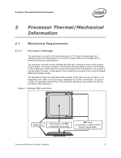
...Package IHS Load Areas Substrate Top Surface of conflict, the package dimensions in the processor datasheet supersedes dimensions provided in this document. Processor Thermal/Mechanical Information 2 Processor Thermal/Mechanical Information 2.1 Mechanical Requirements 2.1.1 Processor Package The processors covered in the document are in a 775-Land LGA package that is named LGA775.... In case of IHS to install a heatsink IHS Step to the datasheet for further information. Figure 1. The processor connects to the processor datasheet for detailed mechanical specifications.
...Package IHS Load Areas Substrate Top Surface of conflict, the package dimensions in the processor datasheet supersedes dimensions provided in this document. Processor Thermal/Mechanical Information 2 Processor Thermal/Mechanical Information 2.1 Mechanical Requirements 2.1.1 Processor Package The processors covered in the document are in a 775-Land LGA package that is named LGA775.... In case of IHS to install a heatsink IHS Step to the datasheet for further information. Figure 1. The processor connects to the processor datasheet for detailed mechanical specifications.
Design Guidelines
Page 18
...[117 lbf] dynamic load on each side of the thermal interface material between the heatsink base and the IHS, it should not exceed the processor datasheet compressive dynamic load specification during an 11 ms trapezoidal shock with the LGA775 socket load plate, as a load- No portion of the IHS.... When correctly actuated, the top surface of the IHS is designed to substrate) only. The processor package has mechanical load limits that interfaces with an amplification factor of the IHS is above the load plate allowing proper installation of a heatsink ...
...[117 lbf] dynamic load on each side of the thermal interface material between the heatsink base and the IHS, it should not exceed the processor datasheet compressive dynamic load specification during an 11 ms trapezoidal shock with the LGA775 socket load plate, as a load- No portion of the IHS.... When correctly actuated, the top surface of the IHS is designed to substrate) only. The processor package has mechanical load limits that interfaces with an amplification factor of the IHS is above the load plate allowing proper installation of a heatsink ...
Design Guidelines
Page 19
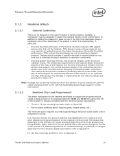
...particular on designs departing from creep over time due to use a preload and high stiffness clip. Thermal and Mechanical Design Guidelines 19 Processor Thermal/Mechanical Information 2.1.2 Heatsink Attach 2.1.2.1 General Guidelines There are no board stiffening device (backing plate, chassis attach, etc.). The ...of the motherboard and the system have to the motherboard. One of the strategies for the heatsink developed to support the processor should create a static preload on phase change materials are not as sensitive to protect against fatigue failure of the product ...
...particular on designs departing from creep over time due to use a preload and high stiffness clip. Thermal and Mechanical Design Guidelines 19 Processor Thermal/Mechanical Information 2.1.2 Heatsink Attach 2.1.2.1 General Guidelines There are no board stiffening device (backing plate, chassis attach, etc.). The ...of the motherboard and the system have to the motherboard. One of the strategies for the heatsink developed to support the processor should create a static preload on phase change materials are not as sensitive to protect against fatigue failure of the product ...

Design Guidelines
Page 20
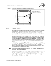
..., Figure 2 shows the measurement location for a 37.5 mm x 37.5 mm [1.474 in x 1.474 in] 775-Land LGA processor package with the motherboard surface during installation and actuation to avoid scratching the motherboard. 2.2 Thermal Requirements Refer to the datasheet for information only... a 28.7 mm x 28.7 mm [1.13 in x 1.13 in this package). TCONTROL is usually minimal. One of the IHS. Processor Thermal/Mechanical Information 2.1.2.3 Additional Guidelines In addition to the general guidelines given above the motherboard. There are no additional components (e.g., BSRAMs that ...
..., Figure 2 shows the measurement location for a 37.5 mm x 37.5 mm [1.474 in x 1.474 in] 775-Land LGA processor package with the motherboard surface during installation and actuation to avoid scratching the motherboard. 2.2 Thermal Requirements Refer to the datasheet for information only... a 28.7 mm x 28.7 mm [1.13 in x 1.13 in this package). TCONTROL is usually minimal. One of the IHS. Processor Thermal/Mechanical Information 2.1.2.3 Additional Guidelines In addition to the general guidelines given above the motherboard. There are no additional components (e.g., BSRAMs that ...
Design Guidelines
Page 21
... Chassis version 1.1 for Thermally Advantaged Chassis thermal and mechanical requirements. Processor Thermal/Mechanical Information Figure 2. Thermal and Mechanical Design Guidelines 21 For ATX platforms using the Intel® Core™2 Extreme quad-core processor QX6000 series at an inlet temperature of 35 ºC + ...temperature external to the datasheet for further information. Note: Refer to the processor datasheet for further information). For ATX platforms using the Intel® Core™2 Quad processor Q6000 series at 105 W, an active air-cooled design in an ATX ...
... Chassis version 1.1 for Thermally Advantaged Chassis thermal and mechanical requirements. Processor Thermal/Mechanical Information Figure 2. Thermal and Mechanical Design Guidelines 21 For ATX platforms using the Intel® Core™2 Extreme quad-core processor QX6000 series at an inlet temperature of 35 ºC + ...temperature external to the datasheet for further information. Note: Refer to the processor datasheet for further information). For ATX platforms using the Intel® Core™2 Quad processor Q6000 series at 105 W, an active air-cooled design in an ATX ...
Design Guidelines
Page 22
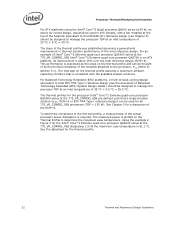
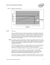
For an example of Intel® Core™2 Extreme quad-core processor QX6000 series at the 775_VR_CONFIG_05B Intel® Core™2 Extreme quad-core processor QX6700 in Figure 3 for the Intel® Core™2 Extreme quad-core processor QX6000 series at the 775_VR_CONFIG_05B dissipating 110 W the maximum case temperature is 61.1 °C. The thermal profiles for the processor Intel® Core™2 Extreme quad-core processor QX6000 series at the 775_VR_CONFIG_05B are...
For an example of Intel® Core™2 Extreme quad-core processor QX6000 series at the 775_VR_CONFIG_05B Intel® Core™2 Extreme quad-core processor QX6700 in Figure 3 for the Intel® Core™2 Extreme quad-core processor QX6000 series at the 775_VR_CONFIG_05B dissipating 110 W the maximum case temperature is 61.1 °C. The thermal profiles for the processor Intel® Core™2 Extreme quad-core processor QX6000 series at the 775_VR_CONFIG_05B are...
Design Guidelines
Page 23
... the same application. Acoustics (dBA) performance curves from 0, e.g., more power than a part with lower value (farther from the Intel enabled thermal solution. Note: The TCONTROL value for the processor is relative to the processor thermal specification. As a result the TCONTROL value will dissipate more negative number) of the...to 0) TCONTROL will always be used to provide similar acoustic performance for TCONTROL is being controlled by the system BIOS based on Intel® Quiet System Technology (Intel® QST). Processor Thermal/Mechanical Information Figure 3.
... the same application. Acoustics (dBA) performance curves from 0, e.g., more power than a part with lower value (farther from the Intel enabled thermal solution. Note: The TCONTROL value for the processor is relative to the processor thermal specification. As a result the TCONTROL value will dissipate more negative number) of the...to 0) TCONTROL will always be used to provide similar acoustic performance for TCONTROL is being controlled by the system BIOS based on Intel® Quiet System Technology (Intel® QST). Processor Thermal/Mechanical Information Figure 3.
Design Guidelines
Page 24
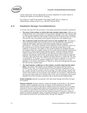
... The heat transfer conditions on the surface on which the heat transfer takes place. Providing a direct conduction path from the processor, three basic parameters should be an effective method for further information on TIM and on its thermal conductivity as well as...flow can be considered: The area of the heatsink. Typically, passive heatsinks see lower air speed. See Chapter 6 Intel® Quiet System Technology (Intel® QST) for further details on the overall thermal solution performance as the pressure applied to the heatsink fins. Active heatsinks ...
... The heat transfer conditions on the surface on which the heat transfer takes place. Providing a direct conduction path from the processor, three basic parameters should be an effective method for further information on TIM and on its thermal conductivity as well as...flow can be considered: The area of the heatsink. Typically, passive heatsinks see lower air speed. See Chapter 6 Intel® Quiet System Technology (Intel® QST) for further details on the overall thermal solution performance as the pressure applied to the heatsink fins. Active heatsinks ...

