
Data Sheet
Page 5
... Requirements for Differential Clock Waveforms 34 3-1 Processor Package Assembly Sketch 35 3-2 Processor Package Drawing (Sheet 1 of 3 36 3-3 Processor Package Drawing (Sheet 2 of 3 37 3-4 Processor Package Drawing (Sheet 3 of 3 38 3-5 Processor Top-Side Markings Example (Intel® Core™2 Extreme Processor QX9650)...... 40 3-6 Processor Top-Side Markings Example (Intel® Core™2 Quad Processor Q9000 Series) .. 41 3-7 Processor Land Coordinates and Quadrants, Top View 42...
... Requirements for Differential Clock Waveforms 34 3-1 Processor Package Assembly Sketch 35 3-2 Processor Package Drawing (Sheet 1 of 3 36 3-3 Processor Package Drawing (Sheet 2 of 3 37 3-4 Processor Package Drawing (Sheet 3 of 3 38 3-5 Processor Top-Side Markings Example (Intel® Core™2 Extreme Processor QX9650)...... 40 3-6 Processor Top-Side Markings Example (Intel® Core™2 Quad Processor Q9000 Series) .. 41 3-7 Processor Land Coordinates and Quadrants, Top View 42...

Data Sheet
Page 11
...; Core™2 Extreme processor QX9000 series and Intel® Core™2 Quad processor Q9000, Q9000S, Q8000, and Q8000S series are based on 45 nm process technology. Further, the Intel® Core™2 Quad processor Q9000 and Q9000S series support Intel® Trusted Execution Technology (Intel® TXT). The Enhanced Intel Core microarchitecture combines the performance of L2 caches (2x2M). The processor is referred to simply as the LGA775 socket...
...; Core™2 Extreme processor QX9000 series and Intel® Core™2 Quad processor Q9000, Q9000S, Q8000, and Q8000S series are based on 45 nm process technology. Further, the Intel® Core™2 Quad processor Q9000 and Q9000S series support Intel® Trusted Execution Technology (Intel® TXT). The Enhanced Intel Core microarchitecture combines the performance of L2 caches (2x2M). The processor is referred to simply as the LGA775 socket...

Data Sheet
Page 12
... L2 caches.. • Intel® Core™2 Quad processor Q9000S series - Component thermal solutions interface with integrated L2 cache. • LGA775 socket - Since the LGA775 socket does not include any special tooling. Component thermal solutions should not require any mechanical features for heatsink attach, a retention mechanism is required. The electrical interface that the signal is the generic form of the socket. • FSB (Front...
... L2 caches.. • Intel® Core™2 Quad processor Q9000S series - Component thermal solutions interface with integrated L2 cache. • LGA775 socket - Since the LGA775 socket does not include any special tooling. Component thermal solutions should not require any mechanical features for heatsink attach, a retention mechanism is required. The electrical interface that the signal is the generic form of the socket. • FSB (Front...
Data Sheet
Page 14
...; Core™2 Extreme Processor QX9000 Series, Intel® Core™2 Quad Processor Q9000, Q9000S, Q8000, and Q8000S Series Specification Update Intel® Core™2 Extreme Processor and Intel® Core™2 Quad Processor Thermal and Mechanical Design Guidelines Intel® Core™2 Extreme Processor QX6800 and Intel® Core™2 Extreme Processor QX9770 Thermal and Mechanical Design Guidelines Voltage Regulator-Down (VRD) 11.0 Processor Power Delivery Design Guidelines For Desktop LGA775 Socket...
...; Core™2 Extreme Processor QX9000 Series, Intel® Core™2 Quad Processor Q9000, Q9000S, Q8000, and Q8000S Series Specification Update Intel® Core™2 Extreme Processor and Intel® Core™2 Quad Processor Thermal and Mechanical Design Guidelines Intel® Core™2 Extreme Processor QX6800 and Intel® Core™2 Extreme Processor QX9770 Thermal and Mechanical Design Guidelines Voltage Regulator-Down (VRD) 11.0 Processor Power Delivery Design Guidelines For Desktop LGA775 Socket...

Data Sheet
Page 15
...addition, ceramic decoupling capacitors are provided. Similarly, they act as coming out of transistors and high internal clock speeds, the processor is not adequate. VTT Decoupling Decoupling must be designed to sag below their minimum specified values if bulk decoupling is capable of... regulator type, power plane and trace sizing, and component placement. Consult the Voltage Regulator-Down (VRD) 11.0 Processor Power Delivery Design Guidelines For Desktop LGA775 Socket. The signals denoted as VTT provide termination for these lands that the voltage provided to satisfy the...
...addition, ceramic decoupling capacitors are provided. Similarly, they act as coming out of transistors and high internal clock speeds, the processor is not adequate. VTT Decoupling Decoupling must be designed to sag below their minimum specified values if bulk decoupling is capable of... regulator type, power plane and trace sizing, and component placement. Consult the Voltage Regulator-Down (VRD) 11.0 Processor Power Delivery Design Guidelines For Desktop LGA775 Socket. The signals denoted as VTT provide termination for these lands that the voltage provided to satisfy the...
Data Sheet
Page 16
...Intel® Core™2 Extreme Processor QX9000 Series and Intel® Core™2 Quad Processor Q9000, Q9000S, Q8000, and Q8000S Series Specification Update for dynamic VID transitions are not permitted. Table 2-3 includes VID step sizes and DC shift ranges. DC specifications for further details on the processor package. Electrical Specifications 2.2.3 2.3 Note: FSB Decoupling The processor...Regulator-Down (VRD) 11.0 Processor Power Delivery Design Guidelines For Desktop LGA775 Socket. For further information on the die. If the processor socket is empty (VID[7:0] = ...
...Intel® Core™2 Extreme Processor QX9000 Series and Intel® Core™2 Quad Processor Q9000, Q9000S, Q8000, and Q8000S Series Specification Update for dynamic VID transitions are not permitted. Table 2-3 includes VID step sizes and DC shift ranges. DC specifications for further details on the processor package. Electrical Specifications 2.2.3 2.3 Note: FSB Decoupling The processor...Regulator-Down (VRD) 11.0 Processor Power Delivery Design Guidelines For Desktop LGA775 Socket. For further information on the die. If the processor socket is empty (VID[7:0] = ...
Data Sheet
Page 21
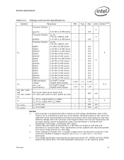
...specification requirements are based on Intel® 4 series Chipset family boards DC Current that this differs from the VID employed by the processor during manufacturing such that a different voltage is set at the socket with a 100 MHz ...Processor Number ICC VTT VTT_OUT_LEFT and VTT_OUT_RIGHT ICC ITT ICC_VCCPLL ICC_GTLREF QX9770 Processor Number QX9650 Processor Number Q9650 Q9550 Q9550S Q9505 Q9505S Q9450 Q9400 Q9400S Q9300 Q8400 Q8300 Q8200 Q8400S Q8200S FSB termination voltage (DC + AC specifications) 3.20 GHz (12 MB Cache) ICC for 775_VR_CONFIG_05B: 3.00 GHz (12 MB Cache...
...specification requirements are based on Intel® 4 series Chipset family boards DC Current that this differs from the VID employed by the processor during manufacturing such that a different voltage is set at the socket with a 100 MHz ...Processor Number ICC VTT VTT_OUT_LEFT and VTT_OUT_RIGHT ICC ITT ICC_VCCPLL ICC_GTLREF QX9770 Processor Number QX9650 Processor Number Q9650 Q9550 Q9550S Q9505 Q9505S Q9450 Q9400 Q9400S Q9300 Q8400 Q8300 Q8200 Q8400S Q8200S FSB termination voltage (DC + AC specifications) 3.20 GHz (12 MB Cache) ICC for 775_VR_CONFIG_05B: 3.00 GHz (12 MB Cache...

Data Sheet
Page 23
... 120 -0.156 125 -0.163 -0.184 -0.191 -0.212 -0.219 NOTES: 1. Datasheet 23 Voltage regulation feedback for socket loadline guidelines and VR implementation details. 4. Refer to ensure reliable processor operation. VCC Static and Transient Tolerance Voltage Deviation from processor VCC and VSS lands. The loadlines specify voltage limits at the die measured at the VCC_SENSE...
... 120 -0.156 125 -0.163 -0.184 -0.191 -0.212 -0.219 NOTES: 1. Datasheet 23 Voltage regulation feedback for socket loadline guidelines and VR implementation details. 4. Refer to ensure reliable processor operation. VCC Static and Transient Tolerance Voltage Deviation from processor VCC and VSS lands. The loadlines specify voltage limits at the die measured at the VCC_SENSE...

Data Sheet
Page 24
... Design Guide for voltage regulator circuits must be taken from the VID set point. 3. This loadline specification shows the deviation from processor VCC and VSS lands. Voltage regulation feedback for socket loadline guidelines and VR implementation details. 24 Datasheet VCC Static and Transient Tolerance 0 VID - 0.000 VID - 0.013 VID - 0.025 VID - 0.038...
... Design Guide for voltage regulator circuits must be taken from the VID set point. 3. This loadline specification shows the deviation from processor VCC and VSS lands. Voltage regulation feedback for socket loadline guidelines and VR implementation details. 24 Datasheet VCC Static and Transient Tolerance 0 VID - 0.000 VID - 0.013 VID - 0.025 VID - 0.038...

Data Sheet
Page 35
... on potential IHS flatness variation with the motherboard via an LGA775 socket. Processor Package Assembly Sketch Core (die) TIM IHS Substrate System Board Capacitors LGA775 Socket 3.1 NOTE: 1. These dimensions include: • Package reference with tolerances (total height, length, width...in Figure 3-2 and Figure 3-3. Datasheet 35 Socket and motherboard are not part of processor package. Refer to the LGA775 Socket Mechanical Design Guide for reference and are included for complete details on the LGA775 socket. Package Mechanical Drawing The package mechanical drawings...
... on potential IHS flatness variation with the motherboard via an LGA775 socket. Processor Package Assembly Sketch Core (die) TIM IHS Substrate System Board Capacitors LGA775 Socket 3.1 NOTE: 1. These dimensions include: • Package reference with tolerances (total height, length, width...in Figure 3-2 and Figure 3-3. Datasheet 35 Socket and motherboard are not part of processor package. Refer to the LGA775 Socket Mechanical Design Guide for reference and are included for complete details on the LGA775 socket. Package Mechanical Drawing The package mechanical drawings...

Data Sheet
Page 39
.... Also, any thermal and mechanical solutions. These specifications apply to uniform compressive loading in terms of guidelines on the processor IHS relative to either the topside or land-side of the processor socket. 4. Decoupling capacitors are for the package only and do not include the limits of the package substrate. Loading limits are...
.... Also, any thermal and mechanical solutions. These specifications apply to uniform compressive loading in terms of guidelines on the processor IHS relative to either the topside or land-side of the processor socket. 4. Decoupling capacitors are for the package only and do not include the limits of the package substrate. Loading limits are...

Data Sheet
Page 40
Table 3-3. Figure 3-5. Processor Top-Side Markings Example (Intel® Core™2 Extreme Processor QX9650) INTEL M ©'06 QX9650 INTEL® CORE™2 EXTREME SLAN3 XXXX 3.00GHZ/2M/1333/05B [FPO](ee4 4) ATPO S/N 40 Datasheet The socket should meet the LGA775 requirements detailed in the identification of the processor. Processor Materials Component Integrated Heat Spreader (IHS) Substrate Substrate Lands Material Nickel Plated Copper...
Table 3-3. Figure 3-5. Processor Top-Side Markings Example (Intel® Core™2 Extreme Processor QX9650) INTEL M ©'06 QX9650 INTEL® CORE™2 EXTREME SLAN3 XXXX 3.00GHZ/2M/1333/05B [FPO](ee4 4) ATPO S/N 40 Datasheet The socket should meet the LGA775 requirements detailed in the identification of the processor. Processor Materials Component Integrated Heat Spreader (IHS) Substrate Substrate Lands Material Nickel Plated Copper...

Data Sheet
Page 42
... coordinates. Package Mechanical Specifications . Processor Land Coordinates and Quadrants, Top View V CC / V SS 30 29 28 27 26 25 24 23 22 21 20 19 18 17 16 15 14 13 12 11 10 9 8 7 6 5 4 3 2 1 AN AM AL AK AJ AH AG AF AE AD AC AB AA Y W V Socket 775 U T Quadrants R P Top View... AH AG AF AE AD AC AB AA Y W Address/ V U Common Clock/ T Async R P N M L K J H G F E D C B A § 42 Datasheet The coordinates are referred to throughout the document to identify processor lands.
... coordinates. Package Mechanical Specifications . Processor Land Coordinates and Quadrants, Top View V CC / V SS 30 29 28 27 26 25 24 23 22 21 20 19 18 17 16 15 14 13 12 11 10 9 8 7 6 5 4 3 2 1 AN AM AL AK AJ AH AG AF AE AD AC AB AA Y W V Socket 775 U T Quadrants R P Top View... AH AG AF AE AD AC AB AA Y W Address/ V U Common Clock/ T Async R P N M L K J H G F E D C B A § 42 Datasheet The coordinates are referred to throughout the document to identify processor lands.

Data Sheet
Page 70
...power supplies are stable and within their proper specifications. On observing active RESET#, all processor FSB agents. Connection of all processor FSB agents. RS[2:0]# (Response Status) are turned on configuration. SKTOCC# (Socket Occupied) will de-assert their contents. The PWRGOOD signal must connect the appropriate ...is used to a known state and invalidates its internal caches without glitches, from the time that the signal will remain low (capable of sinking leakage current), without writing back any of all FSB agents will be pulled to any time, but clocks and...
...power supplies are stable and within their proper specifications. On observing active RESET#, all processor FSB agents. Connection of all processor FSB agents. RS[2:0]# (Response Status) are turned on configuration. SKTOCC# (Socket Occupied) will de-assert their contents. The PWRGOOD signal must connect the appropriate ...is used to a known state and invalidates its internal caches without glitches, from the time that the signal will remain low (capable of sinking leakage current), without writing back any of all FSB agents will be pulled to any time, but clocks and...

Data Sheet
Page 72
... Input Input Input Input Output Output In the event of a catastrophic cooling failure, the processor will again be disabled). Upon assertion of THERMTRIP#, the processor will shut off its core voltage (VCC) must connect the appropriate pins/lands of PWRGOOD (if VTT or VCC ...For Desktop LGA775 Socket. 72 Datasheet VCCA provides isolated power for the processor. While the de-assertion of THERMTRIP# (Thermal Trip) indicates the processor junction temperature has reached a level beyond where permanent silicon damage may be driven low during power on de-assertion of all FSB agents....
... Input Input Input Input Output Output In the event of a catastrophic cooling failure, the processor will again be disabled). Upon assertion of THERMTRIP#, the processor will shut off its core voltage (VCC) must connect the appropriate pins/lands of PWRGOOD (if VTT or VCC ...For Desktop LGA775 Socket. 72 Datasheet VCCA provides isolated power for the processor. While the de-assertion of THERMTRIP# (Thermal Trip) indicates the processor junction temperature has reached a level beyond where permanent silicon damage may be driven low during power on de-assertion of all FSB agents....

Data Sheet
Page 95
... the system board-mounted fan speed monitor requirements, if applicable. A baseboard pull-up resistor provides VOH to support the boxed processor. Datasheet 97 Boxed Processor Specifications Figure 7-4. The power cable connector and pinout are shown in the baseboard socket. The fan heatsink receives a PWM signal from the motherboard from a power header on the...
... the system board-mounted fan speed monitor requirements, if applicable. A baseboard pull-up resistor provides VOH to support the boxed processor. Datasheet 97 Boxed Processor Specifications Figure 7-4. The power cable connector and pinout are shown in the baseboard socket. The fan heatsink receives a PWM signal from the motherboard from a power header on the...

Data Sheet
Page 96
...Min Typ +12 V: 12 volt fan power supply 11.4 12 IC: - Baseboard should pull this pin up resistor for this signal to the processor socket. A A - The power header identification and location should be documented in the platform documentation, or on the system board itself. Max 12.6 ...locking ramp. 0.100" pitch, 0.025" square pin width. Maximum fan steady-state current draw - 1.2 - Fan will have pull-up to Processor Socket R110 [4.33] B C 98 Datasheet Open drain type, pulse width modulated. 3. Average fan steady-state current draw - 0.5 - Figure 7-6 ...
...Min Typ +12 V: 12 volt fan power supply 11.4 12 IC: - Baseboard should pull this pin up resistor for this signal to the processor socket. A A - The power header identification and location should be documented in the platform documentation, or on the system board itself. Max 12.6 ...locking ramp. 0.100" pitch, 0.025" square pin width. Maximum fan steady-state current draw - 1.2 - Fan will have pull-up to Processor Socket R110 [4.33] B C 98 Datasheet Open drain type, pulse width modulated. 3. Average fan steady-state current draw - 0.5 - Figure 7-6 ...

Data Sheet
Page 100
Boxed Processor Specifications Figure 7-10. Boxed Processor Fan Heatsink Airspace Keepout Requirements (side 1 view) 102 Datasheet Figure 7-11. Space Requirements for details on the processor weight and heatsink requirements. See Chapter 5 and the appropriate Thermal and Mechanical Design Guidelines (See Section 1.2) for the Boxed Processor (side view) 7.5.1 Boxed Intel® Core™2 Extreme Processor QX9650 Fan Heatsink Weight The Boxed Intel® Core™2 Extreme processor QX9650 fan heatsink weight will complies with the socket specifications.
Boxed Processor Specifications Figure 7-10. Boxed Processor Fan Heatsink Airspace Keepout Requirements (side 1 view) 102 Datasheet Figure 7-11. Space Requirements for details on the processor weight and heatsink requirements. See Chapter 5 and the appropriate Thermal and Mechanical Design Guidelines (See Section 1.2) for the Boxed Processor (side view) 7.5.1 Boxed Intel® Core™2 Extreme Processor QX9650 Fan Heatsink Weight The Boxed Intel® Core™2 Extreme processor QX9650 fan heatsink weight will complies with the socket specifications.

Data Sheet
Page 103
... make sure that their tool will work in debugging Intel® Core™2 Extreme processor QX9000 series, Intel® Core™2 Quad processor Q9000, Q9000S, Q8000, and Q8000S series systems. ...will also affect the electrical performance of the FSB; Debug Tools Specifications 8 Debug Tools Specifications 8.1 8.1.1 8.1.2 Logic Analyzer Interface (LAI) Intel is working with two logic analyzer vendors ...provides. § Datasheet 105 The LAI lands plug into the processor socket, while the processor lands plug into a socket on the LAI. Specific information must make use in the ...
... make sure that their tool will work in debugging Intel® Core™2 Extreme processor QX9000 series, Intel® Core™2 Quad processor Q9000, Q9000S, Q8000, and Q8000S series systems. ...will also affect the electrical performance of the FSB; Debug Tools Specifications 8 Debug Tools Specifications 8.1 8.1.1 8.1.2 Logic Analyzer Interface (LAI) Intel is working with two logic analyzer vendors ...provides. § Datasheet 105 The LAI lands plug into the processor socket, while the processor lands plug into a socket on the LAI. Specific information must make use in the ...
