Product Guide
Page 6
Intel Desktop Board DG41TY Product Guide Installing a Processor 31 Installing the Processor Fan Heat Sink 34 Connecting the Processor ...Cables 44 Connecting to the Internal Headers and Connectors 45 S/PDIF Connector 46 Front Panel Audio Header 46 Serial Port Header 47 HD Audio Link Header 47 Chassis Intrusion Header 48 Front Panel Header 48 Alternate Front Panel ...European Union Declaration of Conformity Statement 68 Product Ecology Statements 69 Recycling Considerations 69 Lead-Free Desktop Board 71 EMC Regulations 73 Ensure Electromagnetic Compatibility (EMC) Compliance 74 vi
Intel Desktop Board DG41TY Product Guide Installing a Processor 31 Installing the Processor Fan Heat Sink 34 Connecting the Processor ...Cables 44 Connecting to the Internal Headers and Connectors 45 S/PDIF Connector 46 Front Panel Audio Header 46 Serial Port Header 47 HD Audio Link Header 47 Chassis Intrusion Header 48 Front Panel Header 48 Alternate Front Panel ...European Union Declaration of Conformity Statement 68 Product Ecology Statements 69 Recycling Considerations 69 Lead-Free Desktop Board 71 EMC Regulations 73 Ensure Electromagnetic Compatibility (EMC) Compliance 74 vi
Product Guide
Page 7
... Audio Signal Names for the BIOS Setup Program Modes 53 16. BIOS Error Messages 65 18. Intel Desktop Board DG41TY Components 11 2. Location of the BIOS Configuration Jumper Block 53 26. USB 2.0 Header Signal Names 49 15. Jumper Settings for...Feature Summary 9 2. Audio Jack Retasking Support 16 4. Lift the Socket Lever 31 7. Install the Processor 33 11. Intel Desktop Board DG41TY Components 12 3. Lift the Load Plate 32 8. Serial Port Header Signal Names 47 10. Alternate Front Panel Power LED Header 49 14. Contents Product Certifications 75...
... Audio Signal Names for the BIOS Setup Program Modes 53 16. BIOS Error Messages 65 18. Intel Desktop Board DG41TY Components 11 2. Location of the BIOS Configuration Jumper Block 53 26. USB 2.0 Header Signal Names 49 15. Jumper Settings for...Feature Summary 9 2. Audio Jack Retasking Support 16 4. Lift the Socket Lever 31 7. Install the Processor 33 11. Intel Desktop Board DG41TY Components 12 3. Lift the Load Plate 32 8. Serial Port Header Signal Names 47 10. Alternate Front Panel Power LED Header 49 14. Contents Product Certifications 75...
Product Guide
Page 9
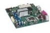
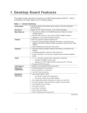
...Intel® Desktop Board DG41TY. 1 Desktop Board Features This chapter briefly describes the features of the Desktop Board. Feature Summary Form Factor Processor Main Memory Chipset Graphics Audio LAN Support Expansion Capabilities Peripheral Interfaces microATX (218.44 millimeters [8.60 inches] x 243.84 millimeters [9.60 inches]) Support for an Intel... • Two PCI* bus connectors • Up to eight USB 2.0 ports ― Four ports routed to the back panel ― Four ports routed to two USB headers • Four Serial ATA (SATA) channels (3.0 Gb/s) via the ICH7 • One IDE ...
...Intel® Desktop Board DG41TY. 1 Desktop Board Features This chapter briefly describes the features of the Desktop Board. Feature Summary Form Factor Processor Main Memory Chipset Graphics Audio LAN Support Expansion Capabilities Peripheral Interfaces microATX (218.44 millimeters [8.60 inches] x 243.84 millimeters [9.60 inches]) Support for an Intel... • Two PCI* bus connectors • Up to eight USB 2.0 ports ― Four ports routed to the back panel ― Four ports routed to two USB headers • Four Serial ATA (SATA) channels (3.0 Gb/s) via the ICH7 • One IDE ...
Product Guide
Page 17
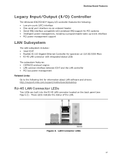
...Figure 2. LAN Connector LEDs 17 Desktop Board Features Legacy Input/Output (I/O) Controller The Winbond 83627DHG-P legacy I/O controller features the following: • Low pin count (LPC) interface • One serial port interface via an onboard header • Serial IRQ interface compatible with serialized IRQ support for PCI systems ... power management Related Links: Go to the following link for information about LAN software and drivers: http://support.intel.com/support/motherboards/desktop RJ-45 LAN Connector LEDs Two LEDs are built into the RJ-45 LAN connector located on the back panel ...
...Figure 2. LAN Connector LEDs 17 Desktop Board Features Legacy Input/Output (I/O) Controller The Winbond 83627DHG-P legacy I/O controller features the following: • Low pin count (LPC) interface • One serial port interface via an onboard header • Serial IRQ interface compatible with serialized IRQ support for PCI systems ... power management Related Links: Go to the following link for information about LAN software and drivers: http://support.intel.com/support/motherboards/desktop RJ-45 LAN Connector LEDs Two LEDs are built into the RJ-45 LAN connector located on the back panel ...
Product Guide
Page 18
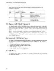
... peripheral devices such as CD-ROM drives) • Older PIO Mode devices • Ultra DMA-33 and ATA-66/100 protocols Serial ATA The Desktop Board supports four Serial ATA channels (3.0 Gb/s) via the ICH7. This may be required to USB 1.1 operation. LAN Connector LEDs LED A B LED...LAN activity is operating. USB 2.0 ports are backward compatible with USB 1.1 devices. The interface supports: • Up to two IDE devices (such as hard drives) • ATAPI-style devices (such as hard disk drives and CD-ROM drives. Intel Desktop Board DG41TY Product Guide Table 4 describes the ...
... peripheral devices such as CD-ROM drives) • Older PIO Mode devices • Ultra DMA-33 and ATA-66/100 protocols Serial ATA The Desktop Board supports four Serial ATA channels (3.0 Gb/s) via the ICH7. This may be required to USB 1.1 operation. LAN Connector LEDs LED A B LED...LAN activity is operating. USB 2.0 ports are backward compatible with USB 1.1 devices. The interface supports: • Up to two IDE devices (such as hard drives) • ATAPI-style devices (such as hard disk drives and CD-ROM drives. Intel Desktop Board DG41TY Product Guide Table 4 describes the ...
Product Guide
Page 47
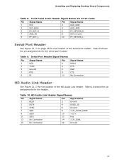
... 3.3V_DUAL 16 Ground 47 Table 9 shows the pin assignments for the location of the serial port header. Table 9. Table 10 shows the pin assignments for the location of the HD Audio Link header. Table 10. Installing and Replacing Desktop Board Components Table 8. Front Panel Audio Header Signal Names for AC'97 Audio Pin Signal...
... 3.3V_DUAL 16 Ground 47 Table 9 shows the pin assignments for the location of the serial port header. Table 9. Table 10 shows the pin assignments for the location of the HD Audio Link header. Table 10. Installing and Replacing Desktop Board Components Table 8. Front Panel Audio Header Signal Names for AC'97 Audio Pin Signal...


