Product Guide
Page 5
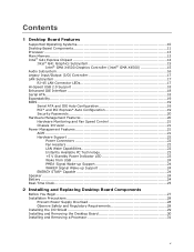
Contents 1 Desktop Board Features Supported Operating Systems 10 Desktop Board Components 11 Processor ...13 Main Memory...13 Intel® G41 Express Chipset 14 Intel® G41 Graphics Subsystem 15 Intel® GMA X4500 Graphics Controller (Intel® GMA X4500 15 Audio Subsystem 16 Legacy Input/Output (I/O) ...up Support 24 ENERGY STAR* Capable 24 Speaker...24 Battery ...24 Real-Time Clock 25 2 Installing and Replacing Desktop Board Components Before You Begin 27 Installation Precautions 28 Prevent Power Supply Overload 28 Observe Safety and Regulatory Requirements 28 Installing ...
Contents 1 Desktop Board Features Supported Operating Systems 10 Desktop Board Components 11 Processor ...13 Main Memory...13 Intel® G41 Express Chipset 14 Intel® G41 Graphics Subsystem 15 Intel® GMA X4500 Graphics Controller (Intel® GMA X4500 15 Audio Subsystem 16 Legacy Input/Output (I/O) ...up Support 24 ENERGY STAR* Capable 24 Speaker...24 Battery ...24 Real-Time Clock 25 2 Installing and Replacing Desktop Board Components Before You Begin 27 Installation Precautions 28 Prevent Power Supply Overload 28 Observe Safety and Regulatory Requirements 28 Installing ...
Product Guide
Page 6
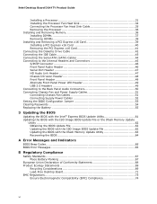
Intel Desktop Board DG41TY Product Guide Installing a Processor 31 Installing the Processor Fan Heat Sink 34 Connecting the Processor Fan Heat Sink Cable 35 Removing the Processor 36 Installing and Removing Memory 36 Installing DIMMs 37 Removing DIMMs 39 Installing and Removing a PCI Express x16 Card 39 Installing a PCI ...Safety Standards 67 Place Battery Marking 67 European Union Declaration of Conformity Statement 68 Product Ecology Statements 69 Recycling Considerations 69 Lead-Free Desktop Board 71 EMC Regulations 73 Ensure Electromagnetic Compatibility (EMC) Compliance 74 vi
Intel Desktop Board DG41TY Product Guide Installing a Processor 31 Installing the Processor Fan Heat Sink 34 Connecting the Processor Fan Heat Sink Cable 35 Removing the Processor 36 Installing and Removing Memory 36 Installing DIMMs 37 Removing DIMMs 39 Installing and Removing a PCI Express x16 Card 39 Installing a PCI ...Safety Standards 67 Place Battery Marking 67 European Union Declaration of Conformity Statement 68 Product Ecology Statements 69 Recycling Considerations 69 Lead-Free Desktop Board 71 EMC Regulations 73 Ensure Electromagnetic Compatibility (EMC) Compliance 74 vi
Product Guide
Page 7
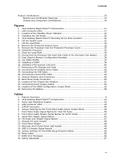
...of the BIOS Configuration Jumper Block 53 26. Lift the Load Plate 32 8. Remove the Protective Socket Cover 32 9. Install the Processor 33 11. Connecting the IDE Cable 43 20. Front Panel Audio Header Signal Names for the BIOS Setup Program Modes 53 16.... Memory Configuration Example 36 14. Front Panel Header 48 13. Alternate Front Panel Power LED Header 49 14. Installing the I/O Shield 29 5. Intel Desktop Board DG41TY Components 11 2. Feature Summary 9 2. LAN Connector LEDs 18 5. USB 2.0 Header Signal Names 49 15. LAN Connector LEDs 17 3. HD Audio...
...of the BIOS Configuration Jumper Block 53 26. Lift the Load Plate 32 8. Remove the Protective Socket Cover 32 9. Install the Processor 33 11. Connecting the IDE Cable 43 20. Front Panel Audio Header Signal Names for the BIOS Setup Program Modes 53 16.... Memory Configuration Example 36 14. Front Panel Header 48 13. Alternate Front Panel Power LED Header 49 14. Installing the I/O Shield 29 5. Intel Desktop Board DG41TY Components 11 2. Feature Summary 9 2. LAN Connector LEDs 18 5. USB 2.0 Header Signal Names 49 15. LAN Connector LEDs 17 3. HD Audio...
Product Guide
Page 9
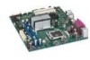
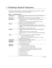
...]) Support for an Intel® processor in the LGA775 package • Two 240-pin, DDR2 1.8 V SDRAM Dual Inline Memory Module (DIMM) sockets • 800/667 MHz single or dual channel DDR2 SDRAM interface • Support for up to 4 GB of system memory Intel® G41 Express Chipset consisting of Intel® Desktop Board DG41TY. 1 Desktop Board Features This chapter...
...]) Support for an Intel® processor in the LGA775 package • Two 240-pin, DDR2 1.8 V SDRAM Dual Inline Memory Module (DIMM) sockets • 800/667 MHz single or dual channel DDR2 SDRAM interface • Support for up to 4 GB of system memory Intel® G41 Express Chipset consisting of Intel® Desktop Board DG41TY. 1 Desktop Board Features This chapter...
Product Guide
Page 13
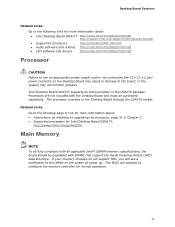
... the following links for more information about : • Intel Desktop Board DG41TY http://www.intel.com/design/motherbd http://support.intel.com/support/motherboards/desktop • Supported processors http://processormatch.intel.com • Audio software and utilities http://www.intel.com/design/motherbd • LAN software and drivers http://www.intel.com/design/motherbd Processor CAUTION Failure to use an appropriate power supply...
... the following links for more information about : • Intel Desktop Board DG41TY http://www.intel.com/design/motherbd http://support.intel.com/support/motherboards/desktop • Supported processors http://processormatch.intel.com • Audio software and utilities http://www.intel.com/design/motherbd • LAN software and drivers http://www.intel.com/design/motherbd Processor CAUTION Failure to use an appropriate power supply...
Product Guide
Page 14
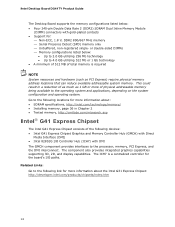
...PCI Express) require physical memory address locations that can reduce available addressable system memory. Intel Desktop Board DG41TY Product Guide The Desktop Board supports the memory configurations listed below : • Up to 2.0 GB utilizing ...256 Mb technology • Up to 4.0 GB utilizing 512 Mb or 1 Gb technology • A minimum of 512 MB of total memory is a centralized controller for the board's I /O Controller Hub (ICH7) with DMI The GMCH component provides interfaces to the processor...
...PCI Express) require physical memory address locations that can reduce available addressable system memory. Intel Desktop Board DG41TY Product Guide The Desktop Board supports the memory configurations listed below : • Up to 2.0 GB utilizing ...256 Mb technology • Up to 4.0 GB utilizing 512 Mb or 1 Gb technology • A minimum of 512 MB of total memory is a centralized controller for the board's I /O Controller Hub (ICH7) with DMI The GMCH component provides interfaces to the processor...
Product Guide
Page 18
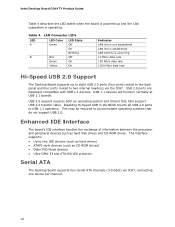
Intel Desktop Board DG41TY Product Guide Table 4 describes the LED states when the board is powered up and the LAN subsystem is occurring 10 Mb/s data rate 100 Mb/s data rate 1000 Mb/s data rate Hi-Speed USB 2.0 Support The Desktop Board supports up to eight USB 2.0 ports (four ports routed.... 18 Enhanced IDE Interface The board's IDE interface handles the exchange of information between the processor and peripheral devices such as CD-ROM drives) • Older PIO Mode devices • Ultra DMA-33 and ATA-66/100 protocols Serial ATA The Desktop Board supports four Serial ATA channels ...
Intel Desktop Board DG41TY Product Guide Table 4 describes the LED states when the board is powered up and the LAN subsystem is occurring 10 Mb/s data rate 100 Mb/s data rate 1000 Mb/s data rate Hi-Speed USB 2.0 Support The Desktop Board supports up to eight USB 2.0 ports (four ports routed.... 18 Enhanced IDE Interface The board's IDE interface handles the exchange of information between the processor and peripheral devices such as CD-ROM drives) • Older PIO Mode devices • Ultra DMA-33 and ATA-66/100 protocols Serial ATA The Desktop Board supports four Serial ATA channels ...
Product Guide
Page 21
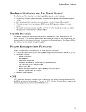
... speed controllers and sensors integrated into the legacy I/O controller • Thermal sensors in the processor, GMCH, and ICH7, plus an onboard remote sensor • Thermally monitored closed-loop fan control, for the location of ACPI with the Desktop Board requires an operating system that detects if the chassis cover has been removed. Power...
... speed controllers and sensors integrated into the legacy I/O controller • Thermal sensors in the processor, GMCH, and ICH7, plus an onboard remote sensor • Thermally monitored closed-loop fan control, for the location of ACPI with the Desktop Board requires an operating system that detects if the chassis cover has been removed. Power...
Product Guide
Page 22
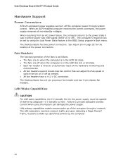
...device. • All fan headers support closed-loop fan control that powers up of the computer through system control. The Desktop Board has a 4-pin processor fan header and two 3-pin chassis fan headers. See Figure 24 on page 52 for the power supply must be set...off the computer power through a network. Failure to the power state it asserts a wake-up signal that can damage the power supply. Intel Desktop Board DG41TY Product Guide Hardware Support Power Connectors ATX12V-compliant power supplies can be capable of delivering adequate +5 V standby current. The computer's response can...
...device. • All fan headers support closed-loop fan control that powers up of the computer through system control. The Desktop Board has a 4-pin processor fan header and two 3-pin chassis fan headers. See Figure 24 on page 52 for the power supply must be set...off the computer power through a network. Failure to the power state it asserts a wake-up signal that can damage the power supply. Intel Desktop Board DG41TY Product Guide Hardware Support Power Connectors ATX12V-compliant power supplies can be capable of delivering adequate +5 V standby current. The computer's response can...
Product Guide
Page 27
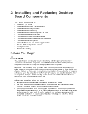
... This chapter tells you how to: • Install the I/O shield • Install and remove the Desktop Board • Install and remove a processor • Install and remove memory • Install and remove a PCI Express x16 card • Connect the diskette drive cable •...Set up a log to disconnect power, telecommunications links, networks, or modems before performing any procedures can damage components. Some circuitry on the board can provide some ESD protection by wearing an antistatic wrist strap and attaching it to a metal part of the procedures described in this chapter...
... This chapter tells you how to: • Install the I/O shield • Install and remove the Desktop Board • Install and remove a processor • Install and remove memory • Install and remove a PCI Express x16 card • Connect the diskette drive cable •...Set up a log to disconnect power, telecommunications links, networks, or modems before performing any procedures can damage components. Some circuitry on the board can provide some ESD protection by wearing an antistatic wrist strap and attaching it to a metal part of the procedures described in this chapter...

Product Guide
Page 28
...on the chassis • Hot components (such as processors, voltage regulators, and heat sinks) • Damage to qualified technical personnel. Prevent Power Supply Overload Do not overload the power supply output. Intel Desktop Board DG41TY Product Guide Installation Precautions When you increase safety risk ...are inconsistent with these instructions and the instructions provided by the chassis and module suppliers, you install and test the Intel Desktop Board, observe all warnings and cautions in this section and the instructions supplied with regional laws and regulations. To avoid...
...on the chassis • Hot components (such as processors, voltage regulators, and heat sinks) • Damage to qualified technical personnel. Prevent Power Supply Overload Do not overload the power supply output. Intel Desktop Board DG41TY Product Guide Installation Precautions When you increase safety risk ...are inconsistent with these instructions and the instructions provided by the chassis and module suppliers, you install and test the Intel Desktop Board, observe all warnings and cautions in this section and the instructions supplied with regional laws and regulations. To avoid...

Product Guide
Page 31
... Before installing or removing the processor, make sure the AC power has been removed by pushing the lever down and away from the computer; Observe the precautions in "Before You Begin" ... cord from the socket (Figure 6, A and B). Figure 6. the standby power LED should not be lit (see Figure 3 on page 27. 2. To install a processor, follow these instructions: 1. Failure to the Desktop Board are given below. Installing and Replacing Desktop Board Components Installing and Removing a Processor Instructions on how to install the processor to do so could damage the...
... Before installing or removing the processor, make sure the AC power has been removed by pushing the lever down and away from the computer; Observe the precautions in "Before You Begin" ... cord from the socket (Figure 6, A and B). Figure 6. the standby power LED should not be lit (see Figure 3 on page 27. 2. To install a processor, follow these instructions: 1. Failure to the Desktop Board are given below. Installing and Replacing Desktop Board Components Installing and Removing a Processor Instructions on how to install the processor to do so could damage the...

Product Guide
Page 32
Do not discard the protective socket cover. Remove the plastic protective socket cover from the socket. Remove the Protective Socket Cover 32 Lift the Load Plate 4. Always replace the socket cover if the processor is removed from the load plate (Figure 8). Intel Desktop Board DG41TY Product Guide 3. Figure 8. Lift the load plate (Figure 7, A). Do not touch the socket contacts (Figure 7, B). Figure 7.
Do not discard the protective socket cover. Remove the plastic protective socket cover from the socket. Remove the Protective Socket Cover 32 Lift the Load Plate 4. Always replace the socket cover if the processor is removed from the load plate (Figure 8). Intel Desktop Board DG41TY Product Guide 3. Figure 8. Lift the load plate (Figure 7, A). Do not touch the socket contacts (Figure 7, B). Figure 7.

Product Guide
Page 33
... Processor Cover 6. Hold the processor with the socket (Figure 10, C). Install the Processor 33 Align notches (Figure 10, B) with your fingers align to touch the bottom of the processor (see Figure 9). Remove the Processor from the socket. Lower the processor straight down without tilting or sliding it in Figure 10. Installing and Replacing Desktop Board Components 5. Remove the processor...
... Processor Cover 6. Hold the processor with the socket (Figure 10, C). Install the Processor 33 Align notches (Figure 10, B) with your fingers align to touch the bottom of the processor (see Figure 9). Remove the Processor from the socket. Lower the processor straight down without tilting or sliding it in Figure 10. Installing and Replacing Desktop Board Components 5. Remove the processor...
Product Guide
Page 34
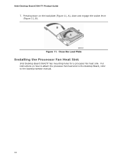
For instructions on the load plate (Figure 11, A), close and engage the socket lever (Figure 11, B). Close the Load Plate Installing the Processor Fan Heat Sink Intel Desktop Board DG41TY has mounting holes for a processor fan heat sink. Pressing down on how to attach the processor fan heat sink to the Desktop Board, refer to the boxed processor manual. 34 Figure 11. Intel Desktop Board DG41TY Product Guide 7.
For instructions on the load plate (Figure 11, A), close and engage the socket lever (Figure 11, B). Close the Load Plate Installing the Processor Fan Heat Sink Intel Desktop Board DG41TY has mounting holes for a processor fan heat sink. Pressing down on how to attach the processor fan heat sink to the Desktop Board, refer to the boxed processor manual. 34 Figure 11. Intel Desktop Board DG41TY Product Guide 7.
Product Guide
Page 35
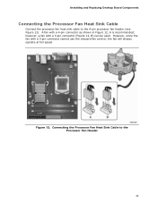
however, a fan with a 3-pin connector cannot use the onboard fan control, the fan will always operate at full speed. However, since the fan with a 3-pin connector (Figure 12, B) can be used. A fan with a 4-pin connector as shown in Figure 12, A is recommended; Figure 12. Installing and Replacing Desktop Board Components Connecting the Processor Fan Heat Sink Cable Connect the processor fan heat sink cable to the Processor Fan Header 35 Connecting the Processor Fan Heat Sink Cable to the 4-pin processor fan header (see Figure 12).
however, a fan with a 3-pin connector cannot use the onboard fan control, the fan will always operate at full speed. However, since the fan with a 3-pin connector (Figure 12, B) can be used. A fan with a 4-pin connector as shown in Figure 12, A is recommended; Figure 12. Installing and Replacing Desktop Board Components Connecting the Processor Fan Heat Sink Cable Connect the processor fan heat sink cable to the Processor Fan Header 35 Connecting the Processor Fan Heat Sink Cable to the 4-pin processor fan header (see Figure 12).
Product Guide
Page 36
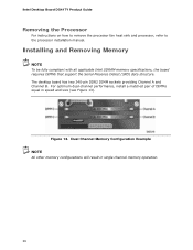
... optimum dual-channel performance, install a matched pair of DIMMs equal in single channel memory operation. 36 Intel Desktop Board DG41TY Product Guide Removing the Processor For instructions on how to remove the processor fan heat sink and processor, refer to the processor installation manual. Figure 13. Installing and Removing Memory NOTE To be fully compliant with all applicable...
... optimum dual-channel performance, install a matched pair of DIMMs equal in single channel memory operation. 36 Intel Desktop Board DG41TY Product Guide Removing the Processor For instructions on how to remove the processor fan heat sink and processor, refer to the processor installation manual. Figure 13. Installing and Removing Memory NOTE To be fully compliant with all applicable...

Product Guide
Page 52
...52 Connect the 12 V processor core voltage power supply cable to the board or the system may result in "Before You Begin" on the Desktop Board is backwards compatible with ATX12V power supplies with 2 x 10 connectors. Figure 24. Intel Desktop Board DG41TY Product Guide Connecting Supply Power... Cables CAUTION Failure to use an appropriate power supply and/or not connecting the 12 V (2 x 2 pin) power connector to the Desktop Board may not function properly. Connect the main ...
...52 Connect the 12 V processor core voltage power supply cable to the board or the system may result in "Before You Begin" on the Desktop Board is backwards compatible with ATX12V power supplies with 2 x 10 connectors. Figure 24. Intel Desktop Board DG41TY Product Guide Connecting Supply Power... Cables CAUTION Failure to use an appropriate power supply and/or not connecting the 12 V (2 x 2 pin) power connector to the Desktop Board may not function properly. Connect the main ...
Product Guide
Page 65
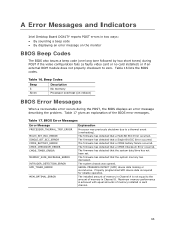
...BIOS Error Messages Error Message PROCESSOR_THERMAL_TRIP_ERROR MULTI_BIT_ECC_ERROR SINGLE_BIT_ECC_ERROR CMOS_BATTERY_ERROR CMOS_CHECKSUM_ERROR CMOS_TIMER_ERROR MEMORY_SIZE_DECREASE_ERROR INTRUDER_DETECTION_ERROR SPD_TOLER_ERROR MEM_OPTIMAL_ERROR Explanation Processor was opened. The firmware has detected that a CMOS battery failure occurred. The firmware has...performance is achieved with equal amounts of the BIOS error messages. A Error Messages and Indicators Intel Desktop Board DG41TY reports POST errors in Channel A is not equal to a thermal event (overheating). Table 16...
...BIOS Error Messages Error Message PROCESSOR_THERMAL_TRIP_ERROR MULTI_BIT_ECC_ERROR SINGLE_BIT_ECC_ERROR CMOS_BATTERY_ERROR CMOS_CHECKSUM_ERROR CMOS_TIMER_ERROR MEMORY_SIZE_DECREASE_ERROR INTRUDER_DETECTION_ERROR SPD_TOLER_ERROR MEM_OPTIMAL_ERROR Explanation Processor was opened. The firmware has detected that a CMOS battery failure occurred. The firmware has...performance is achieved with equal amounts of the BIOS error messages. A Error Messages and Indicators Intel Desktop Board DG41TY reports POST errors in Channel A is not equal to a thermal event (overheating). Table 16...


