Product Guide
Page 6
Intel Desktop Board DG41RQ Product Guide Installing and Removing Memory 34 Installing DIMMs 35 Removing DIMMs 37 Installing and Removing a PCI Express x16 Card 37 Installing a PCI Express x16 Card 38 Removing the PCI Express x16 Card 39 Connecting the IDE Cable 40 Connecting the Serial ATA (SATA) Cables 41 Connecting... Port Header 44 Front Panel Header 45 Alternate Front Panel Power LED Header 45 USB 2.0 Headers 46 Connecting to the Back Panel Audio Connectors 47 Connecting Chassis Fan and Power Supply Cables 48 Connecting a Chassis Fan Cable 48 Connecting Supply Power Cables 49 ...
Intel Desktop Board DG41RQ Product Guide Installing and Removing Memory 34 Installing DIMMs 35 Removing DIMMs 37 Installing and Removing a PCI Express x16 Card 37 Installing a PCI Express x16 Card 38 Removing the PCI Express x16 Card 39 Connecting the IDE Cable 40 Connecting the Serial ATA (SATA) Cables 41 Connecting... Port Header 44 Front Panel Header 45 Alternate Front Panel Power LED Header 45 USB 2.0 Headers 46 Connecting to the Back Panel Audio Connectors 47 Connecting Chassis Fan and Power Supply Cables 48 Connecting a Chassis Fan Cable 48 Connecting Supply Power Cables 49 ...
Product Guide
Page 7
... Cable 40 19. Internal Headers and Connectors 42 21. Back Panel Audio Connectors 47 22. Location of the Rear Chassis Fan Header 48 23. Connecting Power Supply Cables 49 24. Removing the Battery 56 Tables 1. Intel Desktop Board DG41RQ Components 12 3. Front Panel Audio Signal Names for Intel HD Audio 43 6. S/PDIF Connector 43 8. Serial Port Header Signal...
... Cable 40 19. Internal Headers and Connectors 42 21. Back Panel Audio Connectors 47 22. Location of the Rear Chassis Fan Header 48 23. Connecting Power Supply Cables 49 24. Removing the Battery 56 Tables 1. Intel Desktop Board DG41RQ Components 12 3. Front Panel Audio Signal Names for Intel HD Audio 43 6. S/PDIF Connector 43 8. Serial Port Header Signal...

Product Guide
Page 17
Desktop Board Features Legacy Input/Output (I/O) Controller The Winbond 83627DHG-P legacy I/O controller ... • LAN connect interface between ICH7 and the LAN controller • PCI bus power management Go to the following link for information about LAN software and drivers: http://support.intel.com/support/motherboards/desktop Two LEDs are built... into the RJ-45 LAN connector located on the back panel (see Figure 2). Figure 2. These LEDs indicate the status ...
Desktop Board Features Legacy Input/Output (I/O) Controller The Winbond 83627DHG-P legacy I/O controller ... • LAN connect interface between ICH7 and the LAN controller • PCI bus power management Go to the following link for information about LAN software and drivers: http://support.intel.com/support/motherboards/desktop Two LEDs are built... into the RJ-45 LAN connector located on the back panel (see Figure 2). Figure 2. These LEDs indicate the status ...
Product Guide
Page 18
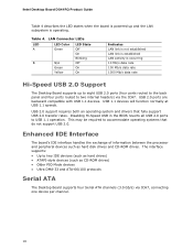
...Intel Desktop Board DG41RQ Product Guide Table 4 describes the LED states when the board is powered up and the LAN subsystem is occurring 10 Mb/s data rate 100 Mb/s data rate 1000 Mb/s data rate Hi-Speed USB 2.0 Support The Desktop Board supports up to eight USB 2.0 ports (four ports routed to the back panel... and four ports routed to two internal headers) via ICH7, connecting one device per channel. 18 USB 2.0 ports are backward compatible with ...
...Intel Desktop Board DG41RQ Product Guide Table 4 describes the LED states when the board is powered up and the LAN subsystem is occurring 10 Mb/s data rate 100 Mb/s data rate 1000 Mb/s data rate Hi-Speed USB 2.0 Support The Desktop Board supports up to eight USB 2.0 ports (four ports routed to the back panel... and four ports routed to two internal headers) via ICH7, connecting one device per channel. 18 USB 2.0 ports are backward compatible with ...
Product Guide
Page 22
... stored in memory. Intel Desktop Board DG41RQ Product Guide • All fan headers support closed-loop fan control that can adjust the fan speed according to provide adequate standby current when using this Desktop Board must be capable of delivering adequate +5 V standby current. Failure to thermal conditions. • All fan headers have a +12 V DC connection. Add-in...
... stored in memory. Intel Desktop Board DG41RQ Product Guide • All fan headers support closed-loop fan control that can adjust the fan speed according to provide adequate standby current when using this Desktop Board must be capable of delivering adequate +5 V standby current. Failure to thermal conditions. • All fan headers have a +12 V DC connection. Add-in...
Product Guide
Page 25
... • Install and remove the Desktop Board • Install and remove a processor • Install and remove memory • Install and remove a PCI Express x16 card • Connect the IDE and Serial ATA cables • Connect to the internal headers and connectors • Connect to operate even though the front panel power button is not available, you...
... • Install and remove the Desktop Board • Install and remove a processor • Install and remove memory • Install and remove a PCI Express x16 card • Connect the IDE and Serial ATA cables • Connect to the internal headers and connectors • Connect to operate even though the front panel power button is not available, you...
Product Guide
Page 45
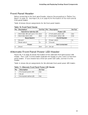
... location of the multi-colored front panel header. Alternate Front Panel Power LED Header Pin Description 1 Front panel green LED 2 No pin 3 Front panel yellow LED In/Out Out Out 45 Installing and Replacing Desktop Board Components Front Panel Header Before connecting to +5 V Out 3 Hard disk active LED Out 2 Front panel green LED 4 Front panel yellow LED Reset Switch On...
... location of the multi-colored front panel header. Alternate Front Panel Power LED Header Pin Description 1 Front panel green LED 2 No pin 3 Front panel yellow LED In/Out Out Out 45 Installing and Replacing Desktop Board Components Front Panel Header Before connecting to +5 V Out 3 Hard disk active LED Out 2 Front panel green LED 4 Front panel yellow LED Reset Switch On...
Product Guide
Page 47
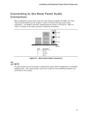
...21. Installing and Replacing Desktop Board Components Connecting to this output. 47 Figure 21 shows the back panel audio connectors. Poor audio quality may occur if passive (non-amplified) speakers are shown in the figure. Back Panel Audio Connectors NOTE The back panel line out connector is designed... information. Refer to power either headphones or amplified speakers only. The default connector assignments are connected to the Back Panel Audio Connectors After installing the audio driver from the Intel Express Installer CD-ROM, the multichannel audio feature can be enabled.
...21. Installing and Replacing Desktop Board Components Connecting to this output. 47 Figure 21 shows the back panel audio connectors. Poor audio quality may occur if passive (non-amplified) speakers are shown in the figure. Back Panel Audio Connectors NOTE The back panel line out connector is designed... information. Refer to power either headphones or amplified speakers only. The default connector assignments are connected to the Back Panel Audio Connectors After installing the audio driver from the Intel Express Installer CD-ROM, the multichannel audio feature can be enabled.


