Product Guide
Page 6
Intel Desktop Board DG41RQ Product Guide Installing and Removing Memory 34 Installing DIMMs 35 Removing DIMMs 37 Installing and Removing a PCI Express x16 Card 37 Installing a PCI Express x16 ... Header 43 S/PDIF Connector 43 Serial Port Header 44 Parallel Port Header 44 Front Panel Header 45 Alternate Front Panel Power LED Header 45 USB 2.0 Headers 46 Connecting to the Back Panel Audio Connectors 47 Connecting Chassis Fan and Power Supply Cables 48 Connecting a Chassis Fan Cable 48 Connecting Supply Power Cables 49...
Intel Desktop Board DG41RQ Product Guide Installing and Removing Memory 34 Installing DIMMs 35 Removing DIMMs 37 Installing and Removing a PCI Express x16 Card 37 Installing a PCI Express x16 ... Header 43 S/PDIF Connector 43 Serial Port Header 44 Parallel Port Header 44 Front Panel Header 45 Alternate Front Panel Power LED Header 45 USB 2.0 Headers 46 Connecting to the Back Panel Audio Connectors 47 Connecting Chassis Fan and Power Supply Cables 48 Connecting a Chassis Fan Cable 48 Connecting Supply Power Cables 49...
Product Guide
Page 7
... Example 34 14. Installing a DIMM 36 16. Connecting the IDE Cable 40 19. Location of the Standby Power Indicator 23 4. Intel Desktop Board DG41RQ Components 12 3. Audio Jack Retasking Support 16 4. BIOS Error Messages 61 16. Location of the BIOS Configuration Jumper Block 50 25.... Sink Cable to the Processor Fan Header ..........33 13. Connecting Power Supply Cables 49 24. Removing the Battery 56 Tables 1. Front Panel Header 45 11. Close the Load Plate 32 12. S/PDIF Connector 43 8. Serial Port Header Signal Names 44 9. EMC Regulations 69...
... Example 34 14. Installing a DIMM 36 16. Connecting the IDE Cable 40 19. Location of the Standby Power Indicator 23 4. Intel Desktop Board DG41RQ Components 12 3. Audio Jack Retasking Support 16 4. BIOS Error Messages 61 16. Location of the BIOS Configuration Jumper Block 50 25.... Sink Cable to the Processor Fan Header ..........33 13. Connecting Power Supply Cables 49 24. Removing the Battery 56 Tables 1. Front Panel Header 45 11. Close the Load Plate 32 12. S/PDIF Connector 43 8. Serial Port Header Signal Names 44 9. EMC Regulations 69...

Product Guide
Page 9
... connector • One PCI Express x1 connector • Two PCI* bus connectors • Up to eight USB 2.0 ports: ― Four ports routed to the back panel ― Four ports routed to two USB headers • Four Serial ATA (SATA) channels (3.0 Gb/s) via the ICH7 • One IDE interface with ATA-66... Inline Memory Module (DIMM) sockets • 800/667 MHz single or dual channel DDR2 SDRAM interface • Support for up to 8 GB of system memory Intel® G41 Express Chipset consisting of Intel® Desktop Board DG41RQ. Table 1 summarizes the major features of the...
... connector • One PCI Express x1 connector • Two PCI* bus connectors • Up to eight USB 2.0 ports: ― Four ports routed to the back panel ― Four ports routed to two USB headers • Four Serial ATA (SATA) channels (3.0 Gb/s) via the ICH7 • One IDE interface with ATA-66... Inline Memory Module (DIMM) sockets • 800/667 MHz single or dual channel DDR2 SDRAM interface • Support for up to 8 GB of system memory Intel® G41 Express Chipset consisting of Intel® Desktop Board DG41RQ. Table 1 summarizes the major features of the...
Product Guide
Page 10
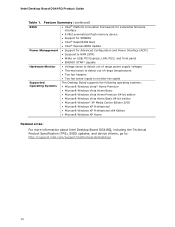
... for SMBIOS • Intel® Rapid BIOS Boot • Intel® Express BIOS Update Power Management • Support for Advanced Configuration and Power Interface (ACPI) • Suspend to RAM (STR) • Wake on USB, PCI Express, LAN, PS/2, and front panel • ENERGY STAR*... Microsoft Windows XP Professional x64 Edition • Microsoft Windows XP Home Related Links: For more information about Intel Desktop Board DG41RQ, including the Technical Product Specification (TPS), BIOS updates, and device drivers, go to: http://support.intel.com/support/motherboards/desktop/ 10
... for SMBIOS • Intel® Rapid BIOS Boot • Intel® Express BIOS Update Power Management • Support for Advanced Configuration and Power Interface (ACPI) • Suspend to RAM (STR) • Wake on USB, PCI Express, LAN, PS/2, and front panel • ENERGY STAR*... Microsoft Windows XP Professional x64 Edition • Microsoft Windows XP Home Related Links: For more information about Intel Desktop Board DG41RQ, including the Technical Product Specification (TPS), BIOS updates, and device drivers, go to: http://support.intel.com/support/motherboards/desktop/ 10

Product Guide
Page 12
... S/PDIF connector Front panel audio header Go to the following links for more information about: • Intel Desktop Board DG41RQ • Supported processors • Audio software and utilities • LAN software and drivers http://www.intel.com/design/motherbd http://support.intel.com/support/motherboards/desktop http://processormatch.intel.com http://www.intel.com/design/motherbd http://www.intel.com/design/motherbd...
... S/PDIF connector Front panel audio header Go to the following links for more information about: • Intel Desktop Board DG41RQ • Supported processors • Audio software and utilities • LAN software and drivers http://www.intel.com/design/motherbd http://support.intel.com/support/motherboards/desktop http://processormatch.intel.com http://www.intel.com/design/motherbd http://www.intel.com/design/motherbd...
Product Guide
Page 16
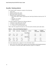
...and utilities http://support.intel.com/support/motherboards/desktop/ • The location of the following: • Intel® ICH7 • Realtek ALC662 audio codec • Back panel audio connectors • Onboard audio headers/connectors: ⎯ Front panel audio header supporting both Intel High Definition Audio ... features: • A signal-to the following link or pages for the front panel and back panel audio jacks. Table 3. Intel Desktop Board DG41RQ Product Guide Audio Subsystem The onboard audio subsystem consists of the back panel audio connectors, Figure 21 on page 47 16
...and utilities http://support.intel.com/support/motherboards/desktop/ • The location of the following: • Intel® ICH7 • Realtek ALC662 audio codec • Back panel audio connectors • Onboard audio headers/connectors: ⎯ Front panel audio header supporting both Intel High Definition Audio ... features: • A signal-to the following link or pages for the front panel and back panel audio jacks. Table 3. Intel Desktop Board DG41RQ Product Guide Audio Subsystem The onboard audio subsystem consists of the back panel audio connectors, Figure 21 on page 47 16

Product Guide
Page 17
Desktop Board Features Legacy Input/Output (I/O) Controller The Winbond 83627DHG-P legacy I/O controller ... programmable wake up event interface • PCI power management support LAN Subsystem The LAN subsystem includes: • Intel ICH7 • Realtek 8111D Gigabit Ethernet Controller for operation at 10/100/1000 Mb/s • RJ-45 LAN...following link for information about LAN software and drivers: http://support.intel.com/support/motherboards/desktop Two LEDs are built into the RJ-45 LAN connector located on the back panel (see Figure 2). LAN Connector LEDs 17 These LEDs indicate ...
Desktop Board Features Legacy Input/Output (I/O) Controller The Winbond 83627DHG-P legacy I/O controller ... programmable wake up event interface • PCI power management support LAN Subsystem The LAN subsystem includes: • Intel ICH7 • Realtek 8111D Gigabit Ethernet Controller for operation at 10/100/1000 Mb/s • RJ-45 LAN...following link for information about LAN software and drivers: http://support.intel.com/support/motherboards/desktop Two LEDs are built into the RJ-45 LAN connector located on the back panel (see Figure 2). LAN Connector LEDs 17 These LEDs indicate ...
Product Guide
Page 18
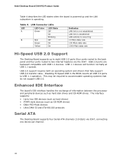
Intel Desktop Board DG41RQ Product Guide Table 4 describes the LED states when the board is powered up and the LAN subsystem is occurring 10 Mb/s data rate 100 Mb/s data rate 1000 Mb/s data rate Hi-Speed USB 2.0 Support The Desktop Board supports up to eight USB 2.0 ports (four ports routed to the back panel ...peripheral devices such as CD-ROM drives) • Older PIO Mode devices • Ultra DMA-33 and ATA-66/100 protocols Serial ATA The Desktop Board supports four Serial ATA channels (3.0 Gb/s) via the ICH7. Disabling Hi-Speed USB in the BIOS reverts all USB 2.0 ports to two internal ...
Intel Desktop Board DG41RQ Product Guide Table 4 describes the LED states when the board is powered up and the LAN subsystem is occurring 10 Mb/s data rate 100 Mb/s data rate 1000 Mb/s data rate Hi-Speed USB 2.0 Support The Desktop Board supports up to eight USB 2.0 ports (four ports routed to the back panel ...peripheral devices such as CD-ROM drives) • Older PIO Mode devices • Ultra DMA-33 and ATA-66/100 protocols Serial ATA The Desktop Board supports four Serial ATA channels (3.0 Gb/s) via the ICH7. Disabling Hi-Speed USB in the BIOS reverts all USB 2.0 ports to two internal ...
Product Guide
Page 22
...wakeup capabilities enable remote wake-up of delivering adequate +5 V standby current. While in power management and can be used with this Desktop Board must be capable of delivering adequate +5 V standby current. Power supplies used to wake the computer. 22 LAN Wake Capabilities CAUTION...panel, the sleep state is indicated by a wake-up the computer. Add-in cards that support this specification can participate in the S3 sleep state, the computer will appear to provide adequate standby current when using this feature can damage the power supply. Intel Desktop Board DG41RQ...
...wakeup capabilities enable remote wake-up of delivering adequate +5 V standby current. While in power management and can be used with this Desktop Board must be capable of delivering adequate +5 V standby current. Power supplies used to wake the computer. 22 LAN Wake Capabilities CAUTION...panel, the sleep state is indicated by a wake-up the computer. Add-in cards that support this specification can participate in the S3 sleep state, the computer will appear to provide adequate standby current when using this feature can damage the power supply. Intel Desktop Board DG41RQ...
Product Guide
Page 25
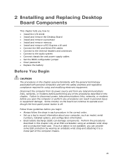
Some circuitry on the board can provide some ESD protection by wearing an antistatic wrist strap and attaching it to operate even though the front panel power button is off. If such a station is not available, you can continue to a metal part of ... links, networks, or modems before performing any procedures can damage components. 2 Installing and Replacing Desktop Board Components This chapter tells you how to: • Install the I/O shield • Install and remove the Desktop Board • Install and remove a processor • Install and remove memory • Install and...
Some circuitry on the board can provide some ESD protection by wearing an antistatic wrist strap and attaching it to operate even though the front panel power button is off. If such a station is not available, you can continue to a metal part of ... links, networks, or modems before performing any procedures can damage components. 2 Installing and Replacing Desktop Board Components This chapter tells you how to: • Install the I/O shield • Install and remove the Desktop Board • Install and remove a processor • Install and remove memory • Install and...
Product Guide
Page 38
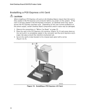
... Card 38 Depending on the system. Secure the card's metal bracket to the chassis back panel with a screw (Figure 16, B). Intel Desktop Board DG41RQ Product Guide Installing a PCI Express x16 Card CAUTION When installing a PCI Express x16 card on the Desktop Board, ensure that the card is fully seated in the PCI Express x16 connector before you...
... Card 38 Depending on the system. Secure the card's metal bracket to the chassis back panel with a screw (Figure 16, B). Intel Desktop Board DG41RQ Product Guide Installing a PCI Express x16 Card CAUTION When installing a PCI Express x16 card on the Desktop Board, ensure that the card is fully seated in the PCI Express x16 connector before you...

Product Guide
Page 39
Pull the card straight up. Push the card ejector lever down using the tip of a pencil or similar tool in "Before You Begin" on page 25. 2. Figure 17. Observe the precautions in the notch (Figure 17, B). Removing a PCI Express x16 Card 39 Remove the screw (Figure 17, A) that secures the card's metal bracket to remove the PCI Express x16 card from the connector (Figure 17, C). 4. This will release the card from the connector: 1. Installing and Replacing Desktop Board Components Removing the PCI Express x16 Card Follow these instructions to the chassis back panel. 3.
Pull the card straight up. Push the card ejector lever down using the tip of a pencil or similar tool in "Before You Begin" on page 25. 2. Figure 17. Observe the precautions in the notch (Figure 17, B). Removing a PCI Express x16 Card 39 Remove the screw (Figure 17, A) that secures the card's metal bracket to remove the PCI Express x16 card from the connector (Figure 17, C). 4. This will release the card from the connector: 1. Installing and Replacing Desktop Board Components Removing the PCI Express x16 Card Follow these instructions to the chassis back panel. 3.
Product Guide
Page 43
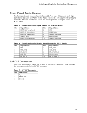
... Name 2 AUD_GND 3 MIC_BIAS 4 AUD_GND 5 FP_OUT_R 7 AUD_5V 9 FP_OUT_L 6 FP_RETURN_R 8 KEY (no pin) 10 SENSE2_RETURN Table 6. Front Panel Audio Header Signal Names for Intel HD Audio Pin Signal Name 1 PORT 1L (Microphone) 3 PORT 1R (Microphone) 5 PORT 2R (Headphone) 7 SENSE_SEND 9 PORT 2L ...connector. Table 7. S/PDIF Connector Pin Description 1 VCC 2 SPDIF OUT 3 Ground 43 Installing and Replacing Desktop Board Components Front Panel Audio Header The front panel audio header shown in Figure 20, A on page 42 shows the location of the S/PDIF connector....
... Name 2 AUD_GND 3 MIC_BIAS 4 AUD_GND 5 FP_OUT_R 7 AUD_5V 9 FP_OUT_L 6 FP_RETURN_R 8 KEY (no pin) 10 SENSE2_RETURN Table 6. Front Panel Audio Header Signal Names for Intel HD Audio Pin Signal Name 1 PORT 1L (Microphone) 3 PORT 1R (Microphone) 5 PORT 2R (Headphone) 7 SENSE_SEND 9 PORT 2L ...connector. Table 7. S/PDIF Connector Pin Description 1 VCC 2 SPDIF OUT 3 Ground 43 Installing and Replacing Desktop Board Components Front Panel Audio Header The front panel audio header shown in Figure 20, A on page 42 shows the location of the S/PDIF connector....
Product Guide
Page 45
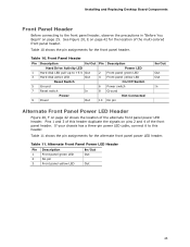
Installing and Replacing Desktop Board Components Front Panel Header Before connecting to this header duplicate the signals on page 42 for the location of the alternate front panel power LED header. Table 10 shows the pin assignments for the alternate front panel power LED header. If your chassis has a ... Description Hard Drive Activity LED Power LED 1 Hard disk LED pull-up to +5 V Out 3 Hard disk active LED Out 2 Front panel green LED 4 Front panel yellow LED Reset Switch On/Off Switch 5 Ground 7 Reset switch 6 Power switch In 8 Ground Power Not Connected 9 Power Out 10...
Installing and Replacing Desktop Board Components Front Panel Header Before connecting to this header duplicate the signals on page 42 for the location of the alternate front panel power LED header. Table 10 shows the pin assignments for the alternate front panel power LED header. If your chassis has a ... Description Hard Drive Activity LED Power LED 1 Hard disk LED pull-up to +5 V Out 3 Hard disk active LED Out 2 Front panel green LED 4 Front panel yellow LED Reset Switch On/Off Switch 5 Ground 7 Reset switch 6 Power switch In 8 Ground Power Not Connected 9 Power Out 10...
Product Guide
Page 47
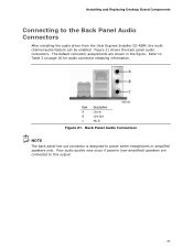
... Figure 21. Figure 21 shows the back panel audio connectors. Back Panel Audio Connectors NOTE The back panel line out connector is designed to Table 3 on page 16 for audio connector retasking information. Installing and Replacing Desktop Board Components Connecting to this output. 47 Poor ...audio quality may occur if passive (non-amplified) speakers are shown in the figure. The default connector assignments are connected to the Back Panel Audio Connectors After installing the audio driver from the Intel ...
... Figure 21. Figure 21 shows the back panel audio connectors. Back Panel Audio Connectors NOTE The back panel line out connector is designed to Table 3 on page 16 for audio connector retasking information. Installing and Replacing Desktop Board Components Connecting to this output. 47 Poor ...audio quality may occur if passive (non-amplified) speakers are shown in the figure. The default connector assignments are connected to the Back Panel Audio Connectors After installing the audio driver from the Intel ...


