Product Guide
Page 5
Contents 1 Desktop Board Features Desktop Board Components 11 Processor ...13 Main Memory...14 Intel® G41 Express Chipset 15 Audio Subsystem 16 Legacy Input/Output (I/O) Controller 17 LAN Subsystem 17 Hi-Speed USB 2.0 Support 18 Enhanced IDE Interface 18 ... Installation Precautions 26 Prevent Power Supply Overload 26 Observe Safety and Regulatory Requirements 26 Installing the I/O Shield 27 Installing and Removing the Desktop Board 28 Installing and Removing a Processor 29 Installing a Processor 29 Installing the Processor Fan Heat Sink 33 Connecting the Processor Fan Heat ...
Contents 1 Desktop Board Features Desktop Board Components 11 Processor ...13 Main Memory...14 Intel® G41 Express Chipset 15 Audio Subsystem 16 Legacy Input/Output (I/O) Controller 17 LAN Subsystem 17 Hi-Speed USB 2.0 Support 18 Enhanced IDE Interface 18 ... Installation Precautions 26 Prevent Power Supply Overload 26 Observe Safety and Regulatory Requirements 26 Installing the I/O Shield 27 Installing and Removing the Desktop Board 28 Installing and Removing a Processor 29 Installing a Processor 29 Installing the Processor Fan Heat Sink 33 Connecting the Processor Fan Heat ...
Product Guide
Page 6
Intel Desktop Board DG41RQ Product Guide Installing and Removing Memory 34 Installing DIMMs 35 Removing DIMMs 37 Installing...40 Connecting the Serial ATA (SATA) Cables 41 Connecting to the Internal Headers and Connectors 42 Front Panel Audio Header 43 S/PDIF Connector 43 Serial Port Header 44 Parallel Port Header 44 Front Panel Header 45 Alternate ...Front Panel Power LED Header 45 USB 2.0 Headers 46 Connecting to the Back Panel Audio Connectors 47 Connecting Chassis Fan and Power Supply Cables 48 Connecting a Chassis Fan Cable 48 Connecting Supply Power ...
Intel Desktop Board DG41RQ Product Guide Installing and Removing Memory 34 Installing DIMMs 35 Removing DIMMs 37 Installing...40 Connecting the Serial ATA (SATA) Cables 41 Connecting to the Internal Headers and Connectors 42 Front Panel Audio Header 43 S/PDIF Connector 43 Serial Port Header 44 Parallel Port Header 44 Front Panel Header 45 Alternate ...Front Panel Power LED Header 45 USB 2.0 Headers 46 Connecting to the Back Panel Audio Connectors 47 Connecting Chassis Fan and Power Supply Cables 48 Connecting a Chassis Fan Cable 48 Connecting Supply Power ...
Product Guide
Page 7
...Card 39 18. Connecting the IDE Cable 40 19. Location of the Standby Power Indicator 23 4. Intel Desktop Board DG41RQ Components 12 3. LAN Connector LEDs 18 5. Front Panel Audio Header Signal Names for the BIOS Setup Program Modes 50 14. Front Panel Header 45 11. ...Jumper Settings for AC'97 Audio 43 7. Intel Desktop Board DG41RQ Components 11 2. Dual Channel Memory Configuration Example 34 14. Use DDR2 DIMMs 35 15. Serial Port Header Signal Names 44 9. Parallel Port Header Signal Names 44 10. Intel Desktop Board DG41RQ Mounting Screw Hole Locations 28 6....
...Card 39 18. Connecting the IDE Cable 40 19. Location of the Standby Power Indicator 23 4. Intel Desktop Board DG41RQ Components 12 3. LAN Connector LEDs 18 5. Front Panel Audio Header Signal Names for the BIOS Setup Program Modes 50 14. Front Panel Header 45 11. ...Jumper Settings for AC'97 Audio 43 7. Intel Desktop Board DG41RQ Components 11 2. Dual Channel Memory Configuration Example 34 14. Use DDR2 DIMMs 35 15. Serial Port Header Signal Names 44 9. Parallel Port Header Signal Names 44 10. Intel Desktop Board DG41RQ Mounting Screw Hole Locations 28 6....

Product Guide
Page 9
... an Intel® processor in multistreaming mode, featuring: ― Realtek* ALC662 audio codec ― Support for Intel® High Definition Audio and AC '97 Audio • Onboard S/PDIF connector Realtek 8111D Gigabit Ethernet Controller for up to 8 GB of system memory Intel® G41 Express Chipset consisting of Intel® Desktop Board DG41RQ. Table 1 summarizes the major features of the Desktop Board.
... an Intel® processor in multistreaming mode, featuring: ― Realtek* ALC662 audio codec ― Support for Intel® High Definition Audio and AC '97 Audio • Onboard S/PDIF connector Realtek 8111D Gigabit Ethernet Controller for up to 8 GB of system memory Intel® G41 Express Chipset consisting of Intel® Desktop Board DG41RQ. Table 1 summarizes the major features of the Desktop Board.

Product Guide
Page 12
Intel Desktop Board DG41RQ Components Label A B C D E F G H I J K L M N O P Q R S T U V W Description PCI bus connector 2 PCI bus connector 1 PCI Express x16 connector...audio header Go to the following links for more information about: • Intel Desktop Board DG41RQ • Supported processors • Audio software and utilities • LAN software and drivers http://www.intel.com/design/motherbd http://support.intel.com/support/motherboards/desktop http://processormatch.intel.com http://www.intel.com/design/motherbd http://www.intel.com/design/motherbd 12 Intel Desktop Board DG41RQ...
Intel Desktop Board DG41RQ Components Label A B C D E F G H I J K L M N O P Q R S T U V W Description PCI bus connector 2 PCI bus connector 1 PCI Express x16 connector...audio header Go to the following links for more information about: • Intel Desktop Board DG41RQ • Supported processors • Audio software and utilities • LAN software and drivers http://www.intel.com/design/motherbd http://support.intel.com/support/motherboards/desktop http://processormatch.intel.com http://www.intel.com/design/motherbd http://www.intel.com/design/motherbd 12 Intel Desktop Board DG41RQ...
Product Guide
Page 16
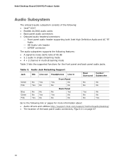
... panel audio connectors • Onboard audio headers/connectors: ⎯ Front panel audio header supporting both Intel High Definition Audio and AC '97 Audio ⎯ HD Audio Link header ⎯ S/PDIF connector The audio subsystem supports the following features: • A signal-to the following link or pages for the front panel and back panel audio jacks. Table 3. Intel Desktop Board DG41RQ Product Guide Audio Subsystem...
... panel audio connectors • Onboard audio headers/connectors: ⎯ Front panel audio header supporting both Intel High Definition Audio and AC '97 Audio ⎯ HD Audio Link header ⎯ S/PDIF connector The audio subsystem supports the following features: • A signal-to the following link or pages for the front panel and back panel audio jacks. Table 3. Intel Desktop Board DG41RQ Product Guide Audio Subsystem...
Product Guide
Page 25
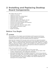
...wrist strap and a conductive foam pad. If such a station is off. 2 Installing and Replacing Desktop Board Components This chapter tells you how to: • Install the I/O shield • Install and remove the Desktop Board • Install and remove a processor • Install and remove memory • Install and ...modems before you begin: • Always follow the steps in each procedure in the correct order. • Set up a log to the audio system • Connect chassis fan and power supply cables • Set the BIOS configuration jumper • Clear passwords • Replace the ...
...wrist strap and a conductive foam pad. If such a station is off. 2 Installing and Replacing Desktop Board Components This chapter tells you how to: • Install the I/O shield • Install and remove the Desktop Board • Install and remove a processor • Install and remove memory • Install and ...modems before you begin: • Always follow the steps in each procedure in the correct order. • Set up a log to the audio system • Connect chassis fan and power supply cables • Set the BIOS configuration jumper • Clear passwords • Replace the ...
Product Guide
Page 43
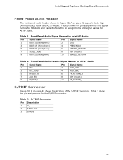
... 9 FP_OUT_L 6 FP_RETURN_R 8 KEY (no pin) 10 SENSE2_RETURN Table 6. Installing and Replacing Desktop Board Components Front Panel Audio Header The front panel audio header shown in Figure 20, A on page 42 shows the location of the S/PDIF connector. Front Panel Audio Header Signal Names for Intel HD Audio Pin Signal Name 1 PORT 1L (Microphone) 3 PORT 1R (Microphone) 5 PORT...
... 9 FP_OUT_L 6 FP_RETURN_R 8 KEY (no pin) 10 SENSE2_RETURN Table 6. Installing and Replacing Desktop Board Components Front Panel Audio Header The front panel audio header shown in Figure 20, A on page 42 shows the location of the S/PDIF connector. Front Panel Audio Header Signal Names for Intel HD Audio Pin Signal Name 1 PORT 1L (Microphone) 3 PORT 1R (Microphone) 5 PORT...
Product Guide
Page 47
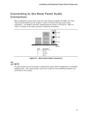
Installing and Replacing Desktop Board Components Connecting to Table 3 on page 16 for audio connector retasking information. Refer to the Back Panel Audio Connectors After installing the audio driver from the Intel Express Installer CD-ROM, the multichannel audio feature can be enabled. Figure 21 shows the back panel audio connectors. Item Description A Line In B Line Out C Mic In...
Installing and Replacing Desktop Board Components Connecting to Table 3 on page 16 for audio connector retasking information. Refer to the Back Panel Audio Connectors After installing the audio driver from the Intel Express Installer CD-ROM, the multichannel audio feature can be enabled. Figure 21 shows the back panel audio connectors. Item Description A Line In B Line Out C Mic In...


