Product Guide
Page 5
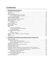
Contents 1 Desktop Board Features Desktop Board Components 12 Processor ...14 System Memory 14 Mobile Intel® 945GSE Express Chipset 14 Intel 945GSE Graphics Subsystem 15 Operating System Support 16 Onboard Audio Subsystem 16 Legacy Input/Output (I/O) Controller 17 Network Bootloader ...the PCI Express Full-Mini Card Slot 34 Installing an Intel® Z-U130 USB Solid-State Drive (or Compatible Device 35 Connecting to the Internal Headers and Connectors 36 Internal Connectors and Headers 37 Connecting a Chassis Fan 46 Setting the BIOS Configuration Jumper 47 Clearing Passwords ...
Contents 1 Desktop Board Features Desktop Board Components 12 Processor ...14 System Memory 14 Mobile Intel® 945GSE Express Chipset 14 Intel 945GSE Graphics Subsystem 15 Operating System Support 16 Onboard Audio Subsystem 16 Legacy Input/Output (I/O) Controller 17 Network Bootloader ...the PCI Express Full-Mini Card Slot 34 Installing an Intel® Z-U130 USB Solid-State Drive (or Compatible Device 35 Connecting to the Internal Headers and Connectors 36 Internal Connectors and Headers 37 Connecting a Chassis Fan 46 Setting the BIOS Configuration Jumper 47 Clearing Passwords ...
Product Guide
Page 7
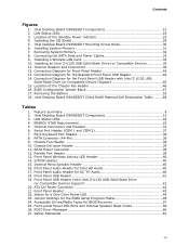
...45 15. ATX12V Power Connector 42 21. States for the Standard Front Panel USB Header 44 14. Removing the Battery 53 18. Intel Desktop Board D945GSEJT Components 13 3. PS/2 Keyboard Port Header 38 8. Internal Mono Speaker Header 40 16. Front Panel USB Header 41 19. Front... for the BIOS Setup Program Modes 48 24. Chassis Intrusion Header 39 11. Contents Figures 1. Chassis Fan Header 38 10. Front Panel Wireless Activity LED Header 40 14. Intel Desktop Board D945GSEJT Components 12 2. Location of the Standby Power Indicator 23 4. S/PDIF Header 40 15. LAN Status ...
...45 15. ATX12V Power Connector 42 21. States for the Standard Front Panel USB Header 44 14. Removing the Battery 53 18. Intel Desktop Board D945GSEJT Components 13 3. PS/2 Keyboard Port Header 38 8. Internal Mono Speaker Header 40 16. Front Panel USB Header 41 19. Front... for the BIOS Setup Program Modes 48 24. Chassis Intrusion Header 39 11. Contents Figures 1. Chassis Fan Header 38 10. Front Panel Wireless Activity LED Header 40 14. Intel Desktop Board D945GSEJT Components 12 2. Location of the Standby Power Indicator 23 4. S/PDIF Header 40 15. LAN Status ...
Product Guide
Page 9
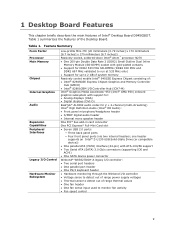
...Atom™ processor N270 • One 200-pin Double Data Rate 2 (DDR2) Small Outline Dual Inline Memory Module (SO-DIMM) socket with support for: • Analog displays (VGA) • Digital displays (DVI-D) RealTek* ALC662 audio codec for up to monitor fan activity • Fan speed control 9 Table 1. Feature Summary Form Factor Processor...: ― Three back panel ports ― Four front panel ports (via two internal headers; Table 1 summarizes the features of Intel® Desktop Board D945GSEJT. 1 Desktop Board Features This chapter briefly describes the main features of the...
...Atom™ processor N270 • One 200-pin Double Data Rate 2 (DDR2) Small Outline Dual Inline Memory Module (SO-DIMM) socket with support for: • Analog displays (VGA) • Digital displays (DVI-D) RealTek* ALC662 audio codec for up to monitor fan activity • Fan speed control 9 Table 1. Feature Summary Form Factor Processor...: ― Three back panel ports ― Four front panel ports (via two internal headers; Table 1 summarizes the features of Intel® Desktop Board D945GSEJT. 1 Desktop Board Features This chapter briefly describes the main features of the...
Product Guide
Page 22
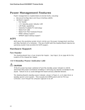
...AC power has been switched off . 22 Hardware Support Fan Header The Desktop Board has a 3-pin chassis fan header. The use of a computer. Failure to do so could damage the board and any devices connected to the board. This includes the DIMM socket and the PCI bus...indicator is still lit, disconnect the power cord before installing or removing any attached devices. Intel Desktop Board D945GSEJT Product Guide Power Management Features Power management is standby power to the system. The Desktop Board's standby power indicator, shown in Figure 3, is lit when there is implemented at ...
...AC power has been switched off . 22 Hardware Support Fan Header The Desktop Board has a 3-pin chassis fan header. The use of a computer. Failure to do so could damage the board and any devices connected to the board. This includes the DIMM socket and the PCI bus...indicator is still lit, disconnect the power cord before installing or removing any attached devices. Intel Desktop Board D945GSEJT Product Guide Power Management Features Power management is standby power to the system. The Desktop Board's standby power indicator, shown in Figure 3, is lit when there is implemented at ...
Product Guide
Page 24
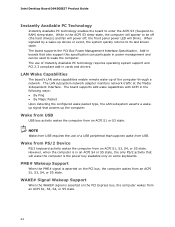
... the computer from USB. NOTE Wake from USB requires the use of a USB peripheral that will blink). Add-in boards that also support this specification can be off (the hard drive(s) and fan will power off, the front panel power LED will wake the computer is asserted on the PCI bus, the...) sleep-state. However, when the computer is asserted on the PCI Express bus, the computer wakes from an ACPI S1, S3, S4, or S5 state. Intel Desktop Board D945GSEJT Product Guide Instantly Available PC Technology Instantly Available PC technology enables the...
... the computer from USB. NOTE Wake from USB requires the use of a USB peripheral that will blink). Add-in boards that also support this specification can be off (the hard drive(s) and fan will power off, the front panel power LED will wake the computer is asserted on the PCI bus, the...) sleep-state. However, when the computer is asserted on the PCI Express bus, the computer wakes from an ACPI S1, S3, S4, or S5 state. Intel Desktop Board D945GSEJT Product Guide Instantly Available PC Technology Instantly Available PC technology enables the...
Product Guide
Page 27
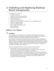
...any telecommunications links, networks, or modems before you begin installing the Desktop Board: • Always follow the steps in each procedure in personal injury or equipment damage. Some circuitry on the board can provide some ESD protection by wearing an antistatic wrist strap and...; Install and remove the Desktop Board • Install and remove system memory • Connect SATA drives • Install a Wireless LAN card • Install an Intel Z-U130 USB Solid-State Drive (or compatible device) • Connect to internal headers • Connect a chassis fan cable • Set the...
...any telecommunications links, networks, or modems before you begin installing the Desktop Board: • Always follow the steps in each procedure in personal injury or equipment damage. Some circuitry on the board can provide some ESD protection by wearing an antistatic wrist strap and...; Install and remove the Desktop Board • Install and remove system memory • Connect SATA drives • Install a Wireless LAN card • Install an Intel Z-U130 USB Solid-State Drive (or compatible device) • Connect to internal headers • Connect a chassis fan cable • Set the...
Product Guide
Page 37
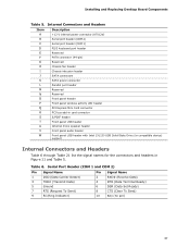
...Installing and Replacing Desktop Board Components Table 5. Internal Connectors and Headers Item A B C D E F G H I J K L M N O P Q R S T U V W Description +12 V internal power connector (ATX12V) Serial port header (COM 2) Serial port header (COM 1) PS/2 keyboard port header Reserved PATA connector (44-pin) Reserved Chassis fan header Chassis intrusion... S/PDIF header Front panel USB header Internal mono speaker header Front panel audio header Front panel USB header with Intel Z-U130 USB Solid-State Drive (or compatible device) support Internal Connectors and Headers Table 6 through Table 21...
...Installing and Replacing Desktop Board Components Table 5. Internal Connectors and Headers Item A B C D E F G H I J K L M N O P Q R S T U V W Description +12 V internal power connector (ATX12V) Serial port header (COM 2) Serial port header (COM 1) PS/2 keyboard port header Reserved PATA connector (44-pin) Reserved Chassis fan header Chassis intrusion... S/PDIF header Front panel USB header Internal mono speaker header Front panel audio header Front panel USB header with Intel Z-U130 USB Solid-State Drive (or compatible device) support Internal Connectors and Headers Table 6 through Table 21...
Product Guide
Page 46
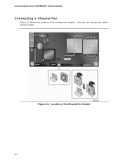
Connect the chassis fan cable to this header. Intel Desktop Board D945GSEJT Product Guide Connecting a Chassis Fan Figure 15 shows the location of the Chassis Fan Header 46 Figure 15. Location of the chassis fan header.
Connect the chassis fan cable to this header. Intel Desktop Board D945GSEJT Product Guide Connecting a Chassis Fan Figure 15 shows the location of the Chassis Fan Header 46 Figure 15. Location of the chassis fan header.


