Product Guide
Page 3
...; Desktop Boards are evaluated as Information Technology Equipment (I.T.E.) for use in personal computers (PC) for other PC or embedded non-PC applications or other environments, such as follows: 1 Desktop Board Features: a summary of product features 2 Installing and Replacing Desktop Board Components: instructions on how to install the Desktop Board and other hardware components 3 Updating the BIOS: a description of how to update the BIOS A BIOS Error Messages: information about BIOS error messages and beep codes...
...; Desktop Boards are evaluated as Information Technology Equipment (I.T.E.) for use in personal computers (PC) for other PC or embedded non-PC applications or other environments, such as follows: 1 Desktop Board Features: a summary of product features 2 Installing and Replacing Desktop Board Components: instructions on how to install the Desktop Board and other hardware components 3 Updating the BIOS: a description of how to update the BIOS A BIOS Error Messages: information about BIOS error messages and beep codes...
Product Guide
Page 5
... 27 Installation Precautions 28 Prevent Power Supply Overload 28 Observe Safety and Regulatory Requirements 28 Installing the I/O Shield 29 Installing and Removing the Desktop Board 30 Installing System Memory 31 Connecting SATA Drives 32 Installing a Wireless LAN Card in the PCI Express Full-Mini Card Slot 34 Installing an Intel® Z-U130 USB Solid-State Drive (or Compatible Device 35 Connecting to the Internal Headers and Connectors 36 Internal Connectors and Headers 37 Connecting a Chassis Fan 46 Setting the BIOS Configuration Jumper 47 Clearing Passwords 48 Replacing the...
... 27 Installation Precautions 28 Prevent Power Supply Overload 28 Observe Safety and Regulatory Requirements 28 Installing the I/O Shield 29 Installing and Removing the Desktop Board 30 Installing System Memory 31 Connecting SATA Drives 32 Installing a Wireless LAN Card in the PCI Express Full-Mini Card Slot 34 Installing an Intel® Z-U130 USB Solid-State Drive (or Compatible Device 35 Connecting to the Internal Headers and Connectors 36 Internal Connectors and Headers 37 Connecting a Chassis Fan 46 Setting the BIOS Configuration Jumper 47 Clearing Passwords 48 Replacing the...
Product Guide
Page 7
...21. Removing System Memory 32 8. BIOS Configuration Jumper Block 47 17. Safety Standards 61 vii Installing System Memory 31 7. Front Panel Audio Header for the Front Panel USB Header with Intel Z-U130 USB Solid-State Drive (or Compatible Device) Support 41 20. Installing a Wireless LAN Card 34 10. Serial Port Header (COM 1 and COM 2 37 7. Chassis Fan Header 38 10. Front Panel Wireless Activity LED Header 40 14. Intel Desktop Board D945GSEJT China RoHS Material Self Declaration Table .........68 Tables 1. Connecting the SATA Data and Power Cables 33 9. Location...
...21. Removing System Memory 32 8. BIOS Configuration Jumper Block 47 17. Safety Standards 61 vii Installing System Memory 31 7. Front Panel Audio Header for the Front Panel USB Header with Intel Z-U130 USB Solid-State Drive (or Compatible Device) Support 41 20. Installing a Wireless LAN Card 34 10. Serial Port Header (COM 1 and COM 2 37 7. Chassis Fan Header 38 10. Front Panel Wireless Activity LED Header 40 14. Intel Desktop Board D945GSEJT China RoHS Material Self Declaration Table .........68 Tables 1. Connecting the SATA Data and Power Cables 33 9. Location...
Product Guide
Page 9
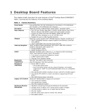
...socket with support for: • Analog displays (VGA) • Digital displays (DVI-D) RealTek* ALC662 audio codec for 2 + 2-channel (multi-streaming) Intel® High Definition Audio (Intel® HD Audio): • Front panel microphone/headphone header • S/PDIF digital audio header • Internal mono speaker header One PCI* bus add-in card connector One PCI Express* Full-Mini Card slot • Seven USB 2.0 ports: ― Three back panel ports ― Four front panel ports (via two internal headers; Feature Summary Form Factor Processor Main Memory Chipset Internal Graphics...
...socket with support for: • Analog displays (VGA) • Digital displays (DVI-D) RealTek* ALC662 audio codec for 2 + 2-channel (multi-streaming) Intel® High Definition Audio (Intel® HD Audio): • Front panel microphone/headphone header • S/PDIF digital audio header • Internal mono speaker header One PCI* bus add-in card connector One PCI Express* Full-Mini Card slot • Seven USB 2.0 ports: ― Three back panel ports ― Four front panel ports (via two internal headers; Feature Summary Form Factor Processor Main Memory Chipset Internal Graphics...
Product Guide
Page 10
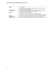
Intel Desktop Board D945GSEJT Product Guide BIOS LAN Support Power Power Management • Intel® BIOS • Support for Advanced Configuration and Power Interface (ACPI), Plug and Play, and SMBIOS • 10/100/1000 Mb/s (Gigabit) Ethernet LAN Subsystem using a RealTek* 8111DL Gigabit Ethernet Controller • Integrated DC-to-DC circuitry • 12 VDC jack on back panel for external power supply • ATX12V 2 x 2 power connector for alternate internal power supply • Support for Advanced Configuration and Power Interface (ACPI) • Wake on USB, PCI, PCI Express, PS...
Intel Desktop Board D945GSEJT Product Guide BIOS LAN Support Power Power Management • Intel® BIOS • Support for Advanced Configuration and Power Interface (ACPI), Plug and Play, and SMBIOS • 10/100/1000 Mb/s (Gigabit) Ethernet LAN Subsystem using a RealTek* 8111DL Gigabit Ethernet Controller • Integrated DC-to-DC circuitry • 12 VDC jack on back panel for external power supply • ATX12V 2 x 2 power connector for alternate internal power supply • Support for Advanced Configuration and Power Interface (ACPI) • Wake on USB, PCI, PCI Express, PS...
Product Guide
Page 14
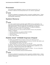
...Chipset The Mobile Intel 945GSE Express Chipset consists of the following devices: • Intel 82945GSE Express Chipset Graphics and Memory Controller Hub (GMCH) with gold-plated contacts. The processor is not customer upgradeable. The Desktop Board has one 200-pin DDR2 SO-DIMM connector with Direct Media Interface (DMI) interconnect • Intel 82801GBM I /O paths. Chassis venting locations are recommended above the processor heatsink area for normal operation. Intel Desktop Board D945GSEJT Product Guide Processor Intel Desktop Board D945GSEJT includes an Intel Atom processor N270...
...Chipset The Mobile Intel 945GSE Express Chipset consists of the following devices: • Intel 82945GSE Express Chipset Graphics and Memory Controller Hub (GMCH) with gold-plated contacts. The processor is not customer upgradeable. The Desktop Board has one 200-pin DDR2 SO-DIMM connector with Direct Media Interface (DMI) interconnect • Intel 82801GBM I /O paths. Chassis venting locations are recommended above the processor heatsink area for normal operation. Intel Desktop Board D945GSEJT Product Guide Processor Intel Desktop Board D945GSEJT includes an Intel Atom processor N270...
Product Guide
Page 17
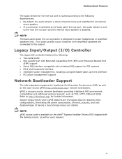
... Enhanced Parallel Port (EPP) support • Serial IRQ interface compatible with the desktop board, as well as TCP, HTTP, DNS and iSCSI. Legacy Input/Output (I/O) Controller The legacy I/O controller features the following dependencies: • By default, the audio stream is down-mixed to mono and amplified for an internal mono speaker. • If a connection is detected at the back panel line-out port, the audio stream is sent...
... Enhanced Parallel Port (EPP) support • Serial IRQ interface compatible with the desktop board, as well as TCP, HTTP, DNS and iSCSI. Legacy Input/Output (I/O) Controller The legacy I/O controller features the following dependencies: • By default, the audio stream is down-mixed to mono and amplified for an internal mono speaker. • If a connection is detected at the back panel line-out port, the audio stream is sent...
Product Guide
Page 18
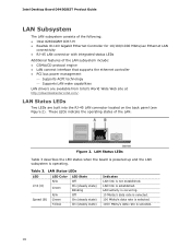
... ethernet controller • PCI bus power management ⎯ Supports ACPI technology ⎯ Supports LAN wake capabilities LAN drivers are built into the RJ-45 LAN connector located on the back panel (see Figure 2). Figure 2. LAN link is not established. Intel Desktop Board D945GSEJT Product Guide LAN Subsystem The LAN subsystem consists of the following: • Intel 82801GBM ICH7-M • Realtek 8111D Gigabit Ethernet Controller for 10/100/1000 Mbits/sec Ethernet LAN connectivity • RJ-45 LAN connector with integrated status LEDs...
... ethernet controller • PCI bus power management ⎯ Supports ACPI technology ⎯ Supports LAN wake capabilities LAN drivers are built into the RJ-45 LAN connector located on the back panel (see Figure 2). Figure 2. LAN link is not established. Intel Desktop Board D945GSEJT Product Guide LAN Subsystem The LAN subsystem consists of the following: • Intel 82801GBM ICH7-M • Realtek 8111D Gigabit Ethernet Controller for 10/100/1000 Mbits/sec Ethernet LAN connectivity • RJ-45 LAN connector with integrated status LEDs...
Product Guide
Page 19
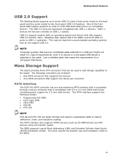
... with USB 1.1 devices. The PATA interface supports the following connectors are backward compatible with 2.5 or 3.5 inch PATA hard drives (including power support for a full-speed USB device. USB 1.1 devices will function normally at USB 1.1 speeds. The drive reports the transfer rate and translation mode to USB 1.1 operation. One of the front panel USB headers supports an Intel Z-U130 USB Solid-State Drive (or compatible device). Desktop Board Features USB 2.0 Support The Desktop Board supports up to seven USB 2.0 ports (three ports routed to the back panel and four ports routed...
... with USB 1.1 devices. The PATA interface supports the following connectors are backward compatible with 2.5 or 3.5 inch PATA hard drives (including power support for a full-speed USB device. USB 1.1 devices will function normally at USB 1.1 speeds. The drive reports the transfer rate and translation mode to USB 1.1 operation. One of the front panel USB headers supports an Intel Z-U130 USB Solid-State Drive (or compatible device). Desktop Board Features USB 2.0 Support The Desktop Board supports up to seven USB 2.0 ports (three ports routed to the back panel and four ports routed...
Product Guide
Page 20
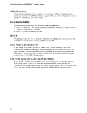
... install a PCI/PCI Express add-in the BIOS automatically detects and configures the device for that support one device per channel. You can support either a single PCI add-in card. You do not need to run the BIOS Setup program after installing an ATA device. PCI/PCI Express Auto Configuration If you install an ATA device (such as a hard drive) in your computer. The connector can override the auto-configuration options by specifying manual configuration in both legacy and native modes. Intel Desktop Board D945GSEJT Product Guide SATA Interface The Desktop Board supports...
... install a PCI/PCI Express add-in the BIOS automatically detects and configures the device for that support one device per channel. You can support either a single PCI add-in card. You do not need to run the BIOS Setup program after installing an ATA device. PCI/PCI Express Auto Configuration If you install an ATA device (such as a hard drive) in your computer. The connector can override the auto-configuration options by specifying manual configuration in both legacy and native modes. Intel Desktop Board D945GSEJT Product Guide SATA Interface The Desktop Board supports...
Product Guide
Page 22
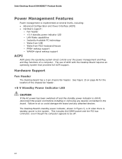
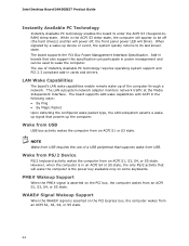
...or removing any attached devices. Hardware Support Fan Header The Desktop Board has a 3-pin chassis fan header. Failure to do so could damage the board and any devices connected to the system. The use of a computer. Intel Desktop Board D945GSEJT Product Guide Power Management Features Power management is implemented at several levels, including: • Advanced Configuration and Power Interface (ACPI) • Hardware support: ― Fan header ― +5 V standby power indicator LED ― LAN Wake capabilities ― Instantly Available PC technology ― Wake from USB ―...
...or removing any attached devices. Hardware Support Fan Header The Desktop Board has a 3-pin chassis fan header. Failure to do so could damage the board and any devices connected to the system. The use of a computer. Intel Desktop Board D945GSEJT Product Guide Power Management Features Power management is implemented at several levels, including: • Advanced Configuration and Power Interface (ACPI) • Hardware support: ― Fan header ― +5 V standby power indicator LED ― LAN Wake capabilities ― Instantly Available PC technology ― Wake from USB ―...
Product Guide
Page 24
... board supports the PCI Bus Power Management Interface Specification. LAN Wake Capabilities The board's LAN wake capabilities enable remote wake-up of Instantly Available PC technology requires operating system support and PCI 2.3 compliant add-in the ACPI S3 sleep-state, the computer will appear to be used to wake the computer. Wake from USB USB bus activity wakes the computer from an ACPI S1, S3, S4, or S5 state. Intel Desktop Board D945GSEJT Product Guide Instantly Available PC Technology Instantly Available PC technology enables...
... board supports the PCI Bus Power Management Interface Specification. LAN Wake Capabilities The board's LAN wake capabilities enable remote wake-up of Instantly Available PC technology requires operating system support and PCI 2.3 compliant add-in the ACPI S3 sleep-state, the computer will appear to be used to wake the computer. Wake from USB USB bus activity wakes the computer from an ACPI S1, S3, S4, or S5 state. Intel Desktop Board D945GSEJT Product Guide Instantly Available PC Technology Instantly Available PC technology enables...
Product Guide
Page 27
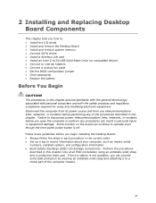
... remove the Desktop Board • Install and remove system memory • Connect SATA drives • Install a Wireless LAN card • Install an Intel Z-U130 USB Solid-State Drive (or compatible device) • Connect to internal headers • Connect a chassis fan cable • Set the BIOS configuration jumper • Clear passwords • Replace the battery Before You Begin CAUTIONS The procedures in this chapter assume familiarity with the general terminology associated with personal computers and with the safety practices and regulatory compliance required for using...
... remove the Desktop Board • Install and remove system memory • Connect SATA drives • Install a Wireless LAN card • Install an Intel Z-U130 USB Solid-State Drive (or compatible device) • Connect to internal headers • Connect a chassis fan cable • Set the BIOS configuration jumper • Clear passwords • Replace the battery Before You Begin CAUTIONS The procedures in this chapter assume familiarity with the general terminology associated with personal computers and with the safety practices and regulatory compliance required for using...
Product Guide
Page 32
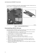
... 4-pin connector on the board (Figure 8, A). 3. Attach the SATA power connector (Figure 8, D) on the power cable to a SATA connector on the Desktop Board (Figure 8, C). 5. The board ships with two data connectors. Attach the right-angled 4-pin power connector on page 27. 2. Attach the other end of the SATA data cable to the mating connector on a SATA drive. 32 Removing System Memory Connecting SATA Drives Intel Desktop Board D945GSEJT supports two SATA drives with an in "Before You Begin" on the power cable to the Desktop Board: 1. Intel Desktop Board D945GSEJT Product Guide...
... 4-pin connector on the board (Figure 8, A). 3. Attach the SATA power connector (Figure 8, D) on the power cable to a SATA connector on the Desktop Board (Figure 8, C). 5. The board ships with two data connectors. Attach the right-angled 4-pin power connector on page 27. 2. Attach the other end of the SATA data cable to the mating connector on a SATA drive. 32 Removing System Memory Connecting SATA Drives Intel Desktop Board D945GSEJT supports two SATA drives with an in "Before You Begin" on the power cable to the Desktop Board: 1. Intel Desktop Board D945GSEJT Product Guide...
Product Guide
Page 37
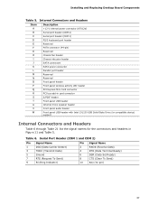
...connector (ATX12V) Serial port header (COM 2) Serial port header (COM 1) PS/2 keyboard port header Reserved PATA connector (44-pin) Reserved Chassis fan header Chassis intrusion header SATA connectors SATA power connector Parallel port header Reserved Reserved Front panel header Front panel wireless activity LED header PCI Express Mini Card connector PCI bus add-in card connector S/PDIF header Front panel USB header Internal mono speaker header Front panel audio header Front panel USB header with Intel Z-U130 USB Solid-State Drive (or compatible device) support Internal Connectors and Headers...
...connector (ATX12V) Serial port header (COM 2) Serial port header (COM 1) PS/2 keyboard port header Reserved PATA connector (44-pin) Reserved Chassis fan header Chassis intrusion header SATA connectors SATA power connector Parallel port header Reserved Reserved Front panel header Front panel wireless activity LED header PCI Express Mini Card connector PCI bus add-in card connector S/PDIF header Front panel USB header Internal mono speaker header Front panel audio header Front panel USB header with Intel Z-U130 USB Solid-State Drive (or compatible device) support Internal Connectors and Headers...

Product Guide
Page 42
... an internal 2 x 2 power connector that can be with a target system that already has an internal power supply. ATX12V Power Connector Pin Signal Name Pin 1 Ground 2 3 +12 V 4 Signal Name Ground +12 V NOTE Use of an external 12 VDC power supply is a connection diagram for general purpose use. Total power consumption will depend on the back panel. Figure 12 is preferred. Intel Desktop Board D945GSEJT Product Guide Power Supply Connectors The board has the following power supply connectors: • External Power Supply - Front Panel Header This...
... an internal 2 x 2 power connector that can be with a target system that already has an internal power supply. ATX12V Power Connector Pin Signal Name Pin 1 Ground 2 3 +12 V 4 Signal Name Ground +12 V NOTE Use of an external 12 VDC power supply is a connection diagram for general purpose use. Total power consumption will depend on the back panel. Figure 12 is preferred. Intel Desktop Board D945GSEJT Product Guide Power Supply Connectors The board has the following power supply connectors: • External Power Supply - Front Panel Header This...
Product Guide
Page 48
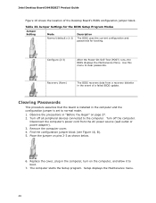
... (wall outlet or power adapter). 3. Turn off all peripheral devices connected to clear passwords. Jumper Settings for the BIOS Setup Program Modes Jumper Setting Mode Normal (default) (1-2) Description The BIOS uses the current configuration and passwords for booting. Observe the precautions in the computer, turn on the computer, and allow it to normal mode. 1. Setup displays the Maintenance menu. 48 Intel Desktop Board D945GSEJT Product Guide Figure 16 shows the location of a failed BIOS update. Table 23. Replace the cover, plug in "Before You Begin...
... (wall outlet or power adapter). 3. Turn off all peripheral devices connected to clear passwords. Jumper Settings for the BIOS Setup Program Modes Jumper Setting Mode Normal (default) (1-2) Description The BIOS uses the current configuration and passwords for booting. Observe the precautions in the computer, turn on the computer, and allow it to normal mode. 1. Setup displays the Maintenance menu. 48 Intel Desktop Board D945GSEJT Product Guide Figure 16 shows the location of a failed BIOS update. Table 23. Replace the cover, plug in "Before You Begin...

Product Guide
Page 49
... Setup displays a pop-up screen requesting that you confirm clearing the password. Turn off the computer. To restore normal operation, place the jumper on pins 1-2 as shown below a certain level, the BIOS Setup program settings stored in CMOS RAM (for example, the date and time) might not be recycled where possible. Replace the cover, plug in the computer, and turn on page 53 shows the location of used batteries...
... Setup displays a pop-up screen requesting that you confirm clearing the password. Turn off the computer. To restore normal operation, place the jumper on pins 1-2 as shown below a certain level, the BIOS Setup program settings stored in CMOS RAM (for example, the date and time) might not be recycled where possible. Replace the cover, plug in the computer, and turn on page 53 shows the location of used batteries...
Product Guide
Page 55
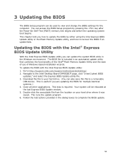
... the executable file from the location on your hard drive. (You can access the BIOS Setup program by either using the Intel Express BIOS Update utility or the Iflash Memory Update utility, and how to http://support.intel.com/support/motherboards/desktop/. 2. This step is included in the dialog boxes to a removable USB device. Follow the instructions provided in an automated update utility that combines the functionality of the Intel® Flash Memory Update Utility and the ease of use of Windows-based installation wizards...
... the executable file from the location on your hard drive. (You can access the BIOS Setup program by either using the Intel Express BIOS Update utility or the Iflash Memory Update utility, and how to http://support.intel.com/support/motherboards/desktop/. 2. This step is included in the dialog boxes to a removable USB device. Follow the instructions provided in an automated update utility that combines the functionality of the Intel® Flash Memory Update Utility and the ease of use of Windows-based installation wizards...

Product Guide
Page 56
... Review the instructions distributed with the Iflash Memory Update Utility You can obtain either of the BIOS by navigating to the USB device. 3. CAUTION Do not interrupt the process or the system may not function properly. The Iflash BIOS update file contains: • New BIOS file • Intel Flash Memory Update Utility You can use the F10 key option during POST to boot to the Intel Desktop Board D945GSEJT page at http://support.intel.com/support/motherboards/desktop. Intel Desktop Board D945GSEJT Product Guide Updating the BIOS with the update utility...
... Review the instructions distributed with the Iflash Memory Update Utility You can obtain either of the BIOS by navigating to the USB device. 3. CAUTION Do not interrupt the process or the system may not function properly. The Iflash BIOS update file contains: • New BIOS file • Intel Flash Memory Update Utility You can use the F10 key option during POST to boot to the Intel Desktop Board D945GSEJT page at http://support.intel.com/support/motherboards/desktop. Intel Desktop Board D945GSEJT Product Guide Updating the BIOS with the update utility...


