
Product Guide
Page 5
Contents 1 Desktop Board Features Desktop Board Components 10 Processor ...12 Main Memory...12 Intel® 945GC Express Chipset 13 Onboard Audio Subsystem 13 Input/Output (I/O) Controller 14 LAN Subsystem 15 LAN Subsystem Software 15 LAN Status LEDs 15 ... ...18 Hardware Support 18 Power Connectors 18 Fan Headers 18 +5 V Standby Power Indicator LED 19 LAN Wake Capabilities 20 Wake from USB 20 Wake from PS/2 Keyboard/Mouse 20 PME# Wakeup Support 20 Battery ...20 Real-Time Clock 20 2 Installing and Replacing Desktop Board Components Before You Begin 21 Installation Precautions 22...
Contents 1 Desktop Board Features Desktop Board Components 10 Processor ...12 Main Memory...12 Intel® 945GC Express Chipset 13 Onboard Audio Subsystem 13 Input/Output (I/O) Controller 14 LAN Subsystem 15 LAN Subsystem Software 15 LAN Status LEDs 15 ... ...18 Hardware Support 18 Power Connectors 18 Fan Headers 18 +5 V Standby Power Indicator LED 19 LAN Wake Capabilities 20 Wake from USB 20 Wake from PS/2 Keyboard/Mouse 20 PME# Wakeup Support 20 Battery ...20 Real-Time Clock 20 2 Installing and Replacing Desktop Board Components Before You Begin 21 Installation Precautions 22...

Product Guide
Page 7
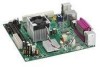
...vii Contents Figures 1. Feature Summary 9 2. BIOS Beep Codes 43 10. Lead-Free Second Level Interconnect Marks 50 13. Intel Desktop Board DG945GCLF Components 10 2. Connecting a 2 x 10 or 2 x 12 Power Supply Cable 33 14. Front Panel Header Signal Names 32 7. ...Fan Header 32 13. Location of the Standby Power Indicator 19 5. Removing the Battery 40 16. Front Panel Audio Header Signal Names for the BIOS Setup Program Modes 35 8. Connecting the IDE Cable 28 10. Hi-Speed USB 2.0 Header Signal Names 31 6. Installing the I/O Shield 23 6. Desktop Board...
...vii Contents Figures 1. Feature Summary 9 2. BIOS Beep Codes 43 10. Lead-Free Second Level Interconnect Marks 50 13. Intel Desktop Board DG945GCLF Components 10 2. Connecting a 2 x 10 or 2 x 12 Power Supply Cable 33 14. Front Panel Header Signal Names 32 7. ...Fan Header 32 13. Location of the Standby Power Indicator 19 5. Removing the Battery 40 16. Front Panel Audio Header Signal Names for the BIOS Setup Program Modes 35 8. Connecting the IDE Cable 28 10. Hi-Speed USB 2.0 Header Signal Names 31 6. Installing the I/O Shield 23 6. Desktop Board...
Product Guide
Page 18
.... See Figure 13 on page 32 for the location of the chassis fan header. 18 See Figure 12 on page 33 for the location of the power connectors. Fan Headers The Desktop Board has a 3-pin MCH fan header and a 3-pin chassis fan header. Intel Desktop Board DG945GCLF Product Guide Power Management Features Power management is implemented at several levels...
.... See Figure 13 on page 32 for the location of the chassis fan header. 18 See Figure 12 on page 33 for the location of the power connectors. Fan Headers The Desktop Board has a 3-pin MCH fan header and a 3-pin chassis fan header. Intel Desktop Board DG945GCLF Product Guide Power Management Features Power management is implemented at several levels...
Product Guide
Page 21
...damage components. Disconnect the computer from its power source and from any telecommunications links, networks, or modems before you begin installing the Desktop Board: • Always follow the steps in each procedure in the correct order. • Set up a log to record information about... • Install the I/O shield • Install and remove the Desktop Board • Install and remove memory • Connect the IDE cable • Connect the SATA cable • Connect internal headers • Connect chassis fan and power supply cables • Set the BIOS configuration and audio ...
...damage components. Disconnect the computer from its power source and from any telecommunications links, networks, or modems before you begin installing the Desktop Board: • Always follow the steps in each procedure in the correct order. • Set up a log to record information about... • Install the I/O shield • Install and remove the Desktop Board • Install and remove memory • Connect the IDE cable • Connect the SATA cable • Connect internal headers • Connect chassis fan and power supply cables • Set the BIOS configuration and audio ...

Product Guide
Page 32
...Figure 11, C on page 21. Table 6 shows the pin assignments for the location of the front panel header. Figure 12. Intel Desktop Board DG945GCLF Product Guide Connecting to the Front Panel Header Before connecting to the front panel header, observe the precautions in "Before You Begin"... on page 30 for the front panel header. Connect the chassis fan cable to +5 V 2 HDR_BLNK_GRN Out Front panel green LED 3 HDA# Out Hard disk active LED 4 HDR_BLNK_YEL Out Front panel yellow LED Reset Switch...
...Figure 11, C on page 21. Table 6 shows the pin assignments for the location of the front panel header. Figure 12. Intel Desktop Board DG945GCLF Product Guide Connecting to the Front Panel Header Before connecting to the front panel header, observe the precautions in "Before You Begin"... on page 30 for the front panel header. Connect the chassis fan cable to +5 V 2 HDR_BLNK_GRN Out Front panel green LED 3 HDA# Out Hard disk active LED 4 HDR_BLNK_YEL Out Front panel yellow LED Reset Switch...
Product Specification
Page 6
Intel Desktop Board D945GCLF Technical Product Specification 2.5.2 Fan Header Current Capability 51 2.5.3 Add-in Board Considerations 52 2.6 Thermal Considerations 52 2.7 Reliability 54 2.8 Environmental 54 3 Overview of BIOS Features 55 3.1 Introduction 55 3.2 BIOS Flash Memory Organization 56 3.3 Resource Configuration...Regulatory Compliance 73 5.1.1 Safety Standards 73 5.1.2 European Union Declaration of Conformity Statement 74 5.1.3 Product Ecology Statements 75 5.1.4 EMC Regulations 79 5.1.5 Product Certification Markings (Board Level 80 5.2 Battery Disposal Information 81 vi
Intel Desktop Board D945GCLF Technical Product Specification 2.5.2 Fan Header Current Capability 51 2.5.3 Add-in Board Considerations 52 2.6 Thermal Considerations 52 2.7 Reliability 54 2.8 Environmental 54 3 Overview of BIOS Features 55 3.1 Introduction 55 3.2 BIOS Flash Memory Organization 56 3.3 Resource Configuration...Regulatory Compliance 73 5.1.1 Safety Standards 73 5.1.2 European Union Declaration of Conformity Statement 74 5.1.3 Product Ecology Statements 75 5.1.4 EMC Regulations 79 5.1.5 Product Certification Markings (Board Level 80 5.2 Battery Disposal Information 81 vi

Product Specification
Page 7
...61 Supervisor and User Password Functions 63 vii Table 2. Table 9. Table 18. Table 22. Table 29. Feature Summary 10 Board Components Shown in Figure 1 13 Supported Memory Configurations 16 Audio Jack Retasking Support 23 LAN Connector LED States 26 Effects of ...-Color Power LED 47 BIOS Setup Configuration Jumper Settings 49 Recommended Power Supply Current Values 51 Fan Header Current Capability 51 Thermal Considerations for Components 53 Desktop Board D945GCLF Environmental Specifications 54 BIOS Setup Program Menu Bar 56 BIOS Setup Program Function Keys 56 Acceptable ...
...61 Supervisor and User Password Functions 63 vii Table 2. Table 9. Table 18. Table 22. Table 29. Feature Summary 10 Board Components Shown in Figure 1 13 Supported Memory Configurations 16 Audio Jack Retasking Support 23 LAN Connector LED States 26 Effects of ...-Color Power LED 47 BIOS Setup Configuration Jumper Settings 49 Recommended Power Supply Current Values 51 Fan Header Current Capability 51 Thermal Considerations for Components 53 Desktop Board D945GCLF Environmental Specifications 54 BIOS Setup Program Menu Bar 56 BIOS Setup Program Function Keys 56 Acceptable ...

Product Specification
Page 11
... SMSC I/O controller • Voltage sense to detect out of range power supply voltages • Thermal sense to detect out of range thermal values • Two fan headers • Two fan sense inputs used to monitor fan activity • Fan speed control 11 Product Description Table 1.
... SMSC I/O controller • Voltage sense to detect out of range power supply voltages • Thermal sense to detect out of range thermal values • Two fan headers • Two fan sense inputs used to monitor fan activity • Fan speed control 11 Product Description Table 1.

Product Specification
Page 27
The board has several hardware management features, including the following: • Thermal and voltage monitoring • Chassis intrusion detection 1.11.1 Hardware Monitoring The features of the hardware monitoring and fan control include: • Internal ambient temperature sensor • Remote thermal diode sensors for direct monitoring...to be compatible with the Wired for Management (WfM) specification. Product Description 1.11 Hardware Management Subsystem The hardware management features enable the board to detect levels above or below acceptable values • SMBus interface 27
The board has several hardware management features, including the following: • Thermal and voltage monitoring • Chassis intrusion detection 1.11.1 Hardware Monitoring The features of the hardware monitoring and fan control include: • Internal ambient temperature sensor • Remote thermal diode sensors for direct monitoring...to be compatible with the Wired for Management (WfM) specification. Product Description 1.11 Hardware Management Subsystem The hardware management features enable the board to detect levels above or below acceptable values • SMBus interface 27

Product Specification
Page 28
Thermal Sensors and Fan Headers 28 Intel Desktop Board D945GCLF Technical Product Specification 1.11.2 Thermal Monitoring Figure 5 shows the locations of the thermal sensors and fan headers. Item A B C Description Remote thermal sensor Chassis fan header Thermal diode, located on processor die Figure 5.
Thermal Sensors and Fan Headers 28 Intel Desktop Board D945GCLF Technical Product Specification 1.11.2 Thermal Monitoring Figure 5 shows the locations of the thermal sensors and fan headers. Item A B C Description Remote thermal sensor Chassis fan header Thermal diode, located on processor die Figure 5.

Product Specification
Page 29
... several levels, including: • Software support through Advanced Configuration and Power Interface (ACPI) • Hardware support: ⎯ Power connector ⎯ Fan headers ⎯ LAN wake capabilities ⎯ Instantly Available PC technology ⎯ Wake from USB ⎯ Wake from PS/2 devices ⎯ Power ...for Off (ACPI G2/G5 - Effects of a computer. working state) Less than four seconds Less than 15-watt system operation in boards may require an ACPI-aware driver), video displays, and hard disk drives • Methods for achieving less than four seconds On (ACPI...
... several levels, including: • Software support through Advanced Configuration and Power Interface (ACPI) • Hardware support: ⎯ Power connector ⎯ Fan headers ⎯ LAN wake capabilities ⎯ Instantly Available PC technology ⎯ Wake from USB ⎯ Wake from PS/2 devices ⎯ Power ...for Off (ACPI G2/G5 - Effects of a computer. working state) Less than four seconds Less than 15-watt system operation in boards may require an ACPI-aware driver), video displays, and hard disk drives • Methods for achieving less than four seconds On (ACPI...

Product Specification
Page 32
...power supply. The total amount of the main power connector Refer to Figure 9, page 42 Table 15, page 45 32 Intel Desktop Board D945GCLF Technical Product Specification 1.12.2 Hardware Support CAUTION Ensure that provides full ACPI support. 1.12.2.1 Power Connector ATX12V-compliant power...names of standby current required depends on or off the system power through system control. The board provides several power management hardware features, including: • Power connector • Fan headers • LAN wake capabilities • Instantly Available PC technology • Wake from ...
...power supply. The total amount of the main power connector Refer to Figure 9, page 42 Table 15, page 45 32 Intel Desktop Board D945GCLF Technical Product Specification 1.12.2 Hardware Support CAUTION Ensure that provides full ACPI support. 1.12.2.1 Power Connector ATX12V-compliant power...names of standby current required depends on or off the system power through system control. The board provides several power management hardware features, including: • Power connector • Fan headers • LAN wake capabilities • Instantly Available PC technology • Wake from ...

Product Specification
Page 33
... names of the GMCH fan header The signal names of the chassis fan header Refer to a fan tachometer input. • All fan headers have a +12 V DC connection. Depending on when the board is in the S0 state. • The fans are on the LAN implementation, the board supports LAN wake capabilities..., S4, or S5 state. • The chassis fan header supports closed-loop fan control that powers up the computer. Product Description 1.12.2.2 Fan Headers The function/operation of the fan headers is as follows: • The fans are off when the board is off or in the following ways: • ...
... names of the GMCH fan header The signal names of the chassis fan header Refer to a fan tachometer input. • All fan headers have a +12 V DC connection. Depending on when the board is in the S0 state. • The fans are on the LAN implementation, the board supports LAN wake capabilities..., S4, or S5 state. • The chassis fan header supports closed-loop fan control that powers up the computer. Product Description 1.12.2.2 Fan Headers The function/operation of the fan headers is as follows: • The fans are off when the board is off or in the following ways: • ...

Product Specification
Page 40
NOTE Computer systems that meets the requirements for full-speed devices. Intel Desktop Board D945GCLF Technical Product Specification 2.2 Connectors and Headers CAUTION Only the following connectors have an unshielded cable attached to a USB port may not meet FCC Class B... external to the computer's chassis. A fault in the load presented by the external devices could cause damage to devices inside the computer's chassis, such as fans and internal peripherals. Do not use these groups: • Back panel I/O connectors (see page 41) • Component-side connectors and headers (see page ...
NOTE Computer systems that meets the requirements for full-speed devices. Intel Desktop Board D945GCLF Technical Product Specification 2.2 Connectors and Headers CAUTION Only the following connectors have an unshielded cable attached to a USB port may not meet FCC Class B... external to the computer's chassis. A fault in the load presented by the external devices could cause damage to devices inside the computer's chassis, such as fans and internal peripherals. Do not use these groups: • Back panel I/O connectors (see page 41) • Component-side connectors and headers (see page ...

Product Specification
Page 43
Table 10. Component-side Connectors and Headers Shown in Figure 9 Item/callout from Figure 9 Description A PCI Conventional bus add-in Figure 9. Technical Reference Table 10 lists the component-side connectors and headers identified in card connector B Front panel audio header Front panel USB headers C +12V power connector (ATX12V) D Chassis fan header E Main power connector F Parallel ATA IDE connector G SATA connector H SATA connector I Front panel I/O header J Front panel USB header 43
Table 10. Component-side Connectors and Headers Shown in Figure 9 Item/callout from Figure 9 Description A PCI Conventional bus add-in Figure 9. Technical Reference Table 10 lists the component-side connectors and headers identified in card connector B Front panel audio header Front panel USB headers C +12V power connector (ATX12V) D Chassis fan header E Main power connector F Parallel ATA IDE connector G SATA connector H SATA connector I Front panel I/O header J Front panel USB header 43

Product Specification
Page 44
... 4 Ground 5 RXN 6 RXP 7 Ground Table 13. Rear Chassis (3-Pin) Fan Header Pin Signal Name 1 Control 2 +12 V 3 Tach Table 14. GMCH (3-Pin) Fan Header Pin Signal Name 1 Control 2 +12 V 3 Tach Signal Name Ground PRESENCE# (Dongle present) [Port 1] SENSE_RETURN Key (no pin) [Port 2] SENSE_RETURN 44 Intel Desktop Board D945GCLF Technical Product Specification 2.2.2.1 Signal Tables for the Connectors and...
... 4 Ground 5 RXN 6 RXP 7 Ground Table 13. Rear Chassis (3-Pin) Fan Header Pin Signal Name 1 Control 2 +12 V 3 Tach Table 14. GMCH (3-Pin) Fan Header Pin Signal Name 1 Control 2 +12 V 3 Tach Signal Name Ground PRESENCE# (Dongle present) [Port 1] SENSE_RETURN Key (no pin) [Port 2] SENSE_RETURN 44 Intel Desktop Board D945GCLF Technical Product Specification 2.2.2.1 Signal Tables for the Connectors and...

Product Specification
Page 51
... Intel Atom processor at 4 W), 2 GB DDR2 RAM, one hard disk drive, one optical drive, and all board peripherals enabled, the minimum recommended power supply is 75 W. Fan Header Current Capability Fan Header Maximum Available Current GMCH fan 2.0 A Rear chassis fan 1.5 A 51 Connecting the processor fan to do so can damage the power supply. The total amount of a D945GCLF board...
... Intel Atom processor at 4 W), 2 GB DDR2 RAM, one hard disk drive, one optical drive, and all board peripherals enabled, the minimum recommended power supply is 75 W. Fan Header Current Capability Fan Header Maximum Available Current GMCH fan 2.0 A Rear chassis fan 1.5 A 51 Connecting the processor fan to do so can damage the power supply. The total amount of a D945GCLF board...

Product Specification
Page 52
... malfunction. Intel Desktop Board D945GCLF Technical Product Specification 2.5.3 Add-in Board Considerations The board is designed to provide 2 A (average) of +5 V current for the one add-in board. The total +5 V current draw for the one add-in board must not...fan inlet is maintained in the processor voltage regulator circuit. Intel makes no warranties or representations that merely following website: http://developer.intel.com/design/motherbd/cooling.htm All responsibility for determining the adequacy of chassis that have been tested with Intel desktop boards please refer to the board...
... malfunction. Intel Desktop Board D945GCLF Technical Product Specification 2.5.3 Add-in Board Considerations The board is designed to provide 2 A (average) of +5 V current for the one add-in board. The total +5 V current draw for the one add-in board must not...fan inlet is maintained in the processor voltage regulator circuit. Intel makes no warranties or representations that merely following website: http://developer.intel.com/design/motherbd/cooling.htm All responsibility for determining the adequacy of chassis that have been tested with Intel desktop boards please refer to the board...


