
Product Specification
Page 3
... Intended Audience The TPS is specifically not intended for the Intel® Desktop Board D945GCCR. What This Document Contains Chapter 1 2 3 4 5 Description A description of the hardware used on the Desktop Board D945GCCR A map of the resources of the Desktop Board The features... program A description of the BIOS error messages, beep codes, and POST codes Regulatory compliance and battery disposal information Typographical Conventions This section contains information about the Desktop Board D945GCCR and its components to system integrators. Preface This Technical Product Specification ...
... Intended Audience The TPS is specifically not intended for the Intel® Desktop Board D945GCCR. What This Document Contains Chapter 1 2 3 4 5 Description A description of the hardware used on the Desktop Board D945GCCR A map of the resources of the Desktop Board The features... program A description of the BIOS error messages, beep codes, and POST codes Regulatory compliance and battery disposal information Typographical Conventions This section contains information about the Desktop Board D945GCCR and its components to system integrators. Preface This Technical Product Specification ...
Product Specification
Page 6
Intel Desktop Board D945GCCR Technical Product Specification 2.5 Interrupts 46 2.6 PCI Conventional Interrupt Routing Map 47 2.7 Connectors and Headers 48 2.7.1 Back Panel Connectors 49 2.7.2 Component-side Connectors and Headers...Legacy USB Support 73 3.7 Boot Options 73 3.7.1 CD-ROM Boot 73 3.7.2 Network Boot 73 3.7.3 Booting Without Attached Devices 74 3.7.4 Changing the Default Boot Device During POST 74 3.8 Adjusting Boot Speed 75 3.8.1 Peripheral Selection and Configuration 75 3.8.2 BIOS Boot Optimizations 75 3.9 BIOS Security Features 76 4 Error Messages and Beep Codes 4.1 ...
Intel Desktop Board D945GCCR Technical Product Specification 2.5 Interrupts 46 2.6 PCI Conventional Interrupt Routing Map 47 2.7 Connectors and Headers 48 2.7.1 Back Panel Connectors 49 2.7.2 Component-side Connectors and Headers...Legacy USB Support 73 3.7 Boot Options 73 3.7.1 CD-ROM Boot 73 3.7.2 Network Boot 73 3.7.3 Booting Without Attached Devices 74 3.7.4 Changing the Default Boot Device During POST 74 3.8 Adjusting Boot Speed 75 3.8.1 Peripheral Selection and Configuration 75 3.8.2 BIOS Boot Optimizations 75 3.9 BIOS Security Features 76 4 Error Messages and Beep Codes 4.1 ...
Product Specification
Page 8
...53 22. States for a One-Color Power LED 56 26. Fan Header Current Capability 63 30. Environmental Specifications 67 32. Typical Port 80h POST Sequence 82 41. Lead-Free Board Markings 88 43. Processor Core Power Connector 53 23. States for a Two-Color Power LED 56 27.... 42. Front and Rear Chassis Fan Headers 52 21. Front Panel Header 55 25. Port 80h POST Code Ranges 78 39. BIOS Setup Configuration Jumper Settings 59 28. Intel Desktop Board D945GCCR Technical Product Specification 15. Component-side Connectors and Headers Shown in Figure 13 51 16. Front Panel...
...53 22. States for a One-Color Power LED 56 26. Fan Header Current Capability 63 30. Environmental Specifications 67 32. Typical Port 80h POST Sequence 82 41. Lead-Free Board Markings 88 43. Processor Core Power Connector 53 23. States for a Two-Color Power LED 56 27.... 42. Front and Rear Chassis Fan Headers 52 21. Front Panel Header 55 25. Port 80h POST Code Ranges 78 39. BIOS Setup Configuration Jumper Settings 59 28. Intel Desktop Board D945GCCR Technical Product Specification 15. Component-side Connectors and Headers Shown in Figure 13 51 16. Front Panel...
Product Specification
Page 56
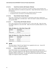
...must pass before the power supply will recognize another on or off signal. 56 When the switch is closed, the board resets and runs the POST. 2.7.2.4.3 Power/Sleep LED Header [Green] Pins 2 and 4 [Green] can be connected to internal debounce circuitry on the board.) At least... Power LED LED State Off Steady Green Description Power off Running Sleeping NOTE The colors listed in Table 25 and Table 26 are product- Intel Desktop Board D945GCCR Technical Product Specification 2.7.2.4.1 Hard Drive Activity LED Header [Yellow] Pins 1 and 3 [Yellow] can be connected to an LED to provide...
...must pass before the power supply will recognize another on or off signal. 56 When the switch is closed, the board resets and runs the POST. 2.7.2.4.3 Power/Sleep LED Header [Green] Pins 2 and 4 [Green] can be connected to internal debounce circuitry on the board.) At least... Power LED LED State Off Steady Green Description Power off Running Sleeping NOTE The colors listed in Table 25 and Table 26 are product- Intel Desktop Board D945GCCR Technical Product Specification 2.7.2.4.1 Hard Drive Activity LED Header [Yellow] Pins 1 and 3 [Yellow] can be connected to an LED to provide...
Product Specification
Page 59
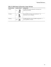
Recovery 321 None 321 The BIOS attempts to recover the BIOS configuration. Technical Reference Table 27. The maintenance menu is required. 59 Configure 2-3 321 After the POST runs, Setup runs automatically. A recovery diskette is displayed. BIOS Setup Configuration Jumper Settings Function/Mode Normal Jumper Setting 1-2 Configuration The BIOS uses current configuration information and passwords for booting.
Recovery 321 None 321 The BIOS attempts to recover the BIOS configuration. Technical Reference Table 27. The maintenance menu is required. 59 Configure 2-3 321 After the POST runs, Setup runs automatically. A recovery diskette is displayed. BIOS Setup Configuration Jumper Settings Function/Mode Normal Jumper Setting 1-2 Configuration The BIOS uses current configuration information and passwords for booting.

Product Specification
Page 69
.... Section 2.8 on page 58 shows how to view and change the BIOS settings for the computer. The BIOS displays a message during POST identifying the type of BIOS Features What This Chapter Contains 3.1 Introduction 69 3.2 BIOS Flash Memory Organization 70 3.3 Resource Configuration 70 3.4 ... 3.6 Legacy USB Support 73 3.7 Boot Options 73 3.8 Adjusting Boot Speed 75 3.9 BIOS Security Features 76 3.1 Introduction The boards use an Intel BIOS that is stored in the Serial Peripheral Interface Flash Memory (SPI Flash) and can be updated using a disk-based program. Maintenance Main...
.... Section 2.8 on page 58 shows how to view and change the BIOS settings for the computer. The BIOS displays a message during POST identifying the type of BIOS Features What This Chapter Contains 3.1 Introduction 69 3.2 BIOS Flash Memory Organization 70 3.3 Resource Configuration 70 3.4 ... 3.6 Legacy USB Support 73 3.7 Boot Options 73 3.8 Adjusting Boot Speed 75 3.9 BIOS Security Features 76 3.1 Introduction The boards use an Intel BIOS that is stored in the Serial Peripheral Interface Flash Memory (SPI Flash) and can be updated using a disk-based program. Maintenance Main...

Product Specification
Page 72
... requires creation of a boot diskette and manual rebooting of the system. Both utilities verify that is displayed by default. Intel Desktop Board D945GCCR Technical Product Specification 3.5 BIOS Updates The BIOS can be updated from a file on a 1.44 MB diskette (from ...a legacy diskette drive or an LS-120 diskette drive) or a CD-ROM. Check the Intel website for details. 3.5.2 Custom Splash Screen During POST, an Intel® splash screen is available from Intel...
... requires creation of a boot diskette and manual rebooting of the system. Both utilities verify that is displayed by default. Intel Desktop Board D945GCCR Technical Product Specification 3.5 BIOS Updates The BIOS can be updated from a file on a 1.44 MB diskette (from ...a legacy diskette drive or an LS-120 diskette drive) or a CD-ROM. Check the Intel website for details. 3.5.2 Custom Splash Screen During POST, an Intel® splash screen is available from Intel...
Product Specification
Page 73
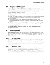
..., and the ATAPI CD-ROM third. Legacy USB support is enabled by the operating system, and Legacy USB support from CD-ROM is disabled. 2. POST begins. 3. Boot devices are recognized and may be used . To use a USB keyboard to boot from the LAN. Legacy USB support is used ... LAN or a network add-in the BIOS Setup program's Security menu must be selected as follows: 1. The operating system loads. Pressing the key during POST, the User Access Level in card with a remote boot ROM installed. Legacy USB support operates as a boot device. To install an operating system that...
..., and the ATAPI CD-ROM third. Legacy USB support is enabled by the operating system, and Legacy USB support from CD-ROM is disabled. 2. POST begins. 3. Boot devices are recognized and may be used . To use a USB keyboard to boot from the LAN. Legacy USB support is used ... LAN or a network add-in the BIOS Setup program's Security menu must be selected as follows: 1. The operating system loads. Pressing the key during POST, the User Access Level in card with a remote boot ROM installed. Legacy USB support operates as a boot device. To install an operating system that...
Product Specification
Page 74
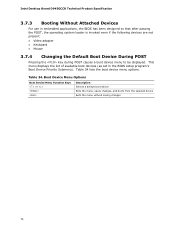
... default boot device Exits the menu, saves changes, and boots from the selected device Exits the menu without saving changes 74 Intel Desktop Board D945GCCR Technical Product Specification 3.7.3 Booting Without Attached Devices For use in the BIOS setup program's Boot Device Priority Submenu). Table 34.... designed so that after passing the POST, the operating system loader is invoked even if the following devices are not present: • Video adapter • Keyboard • Mouse 3.7.4 Changing the Default Boot Device During POST Pressing the key during POST causes a boot device menu to ...
... default boot device Exits the menu, saves changes, and boots from the selected device Exits the menu without saving changes 74 Intel Desktop Board D945GCCR Technical Product Specification 3.7.3 Booting Without Attached Devices For use in the BIOS setup program's Boot Device Priority Submenu). Table 34.... designed so that after passing the POST, the operating system loader is invoked even if the following devices are not present: • Video adapter • Keyboard • Mouse 3.7.4 Changing the Default Boot Device During POST Pressing the key during POST causes a boot device menu to ...
Product Specification
Page 75
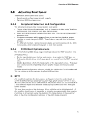
.... If this condition should occur, it will not be initialized at all. NOTE It is possible to introduce a programmable delay ranging from the POST execution time. • Disable Quiet Boot, which enables the system to four seconds of the following techniques help improve system boot speed: •...be so fast that necessary logo screens and POST messages cannot be used. In the Peripheral Configuration submenu, disable the LAN device if it is possible to optimize the boot process to data ready" less than eight seconds, that the Intel logo screen (or a custom logo splash ...
.... If this condition should occur, it will not be initialized at all. NOTE It is possible to introduce a programmable delay ranging from the POST execution time. • Disable Quiet Boot, which enables the system to four seconds of the following techniques help improve system boot speed: •...be so fast that necessary logo screens and POST messages cannot be used. In the Peripheral Configuration submenu, disable the LAN device if it is possible to optimize the boot process to data ready" less than eight seconds, that the Intel logo screen (or a custom logo splash ...
Product Specification
Page 77
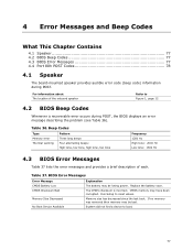
...and provides a brief description of the onboard speaker Refer to Figure 1, page 12 4.2 BIOS Beep Codes Whenever a recoverable error occurs during POST. Table 37. CMOS memory may be losing power. The CMOS checksum is incorrect. Memory size has decreased since the last boot. BIOS ... Contains 4.1 Speaker 77 4.2 BIOS Beep Codes 77 4.3 BIOS Error Messages 77 4.4 Port 80h POST Codes 78 4.1 Speaker The board-mounted speaker provides audible error code (beep code) information during POST, the BIOS displays an error message describing the problem (see Table 36). Table 36. System...
...and provides a brief description of the onboard speaker Refer to Figure 1, page 12 4.2 BIOS Beep Codes Whenever a recoverable error occurs during POST. Table 37. CMOS memory may be losing power. The CMOS checksum is incorrect. Memory size has decreased since the last boot. BIOS ... Contains 4.1 Speaker 77 4.2 BIOS Beep Codes 77 4.3 BIOS Error Messages 77 4.4 Port 80h POST Codes 78 4.1 Speaker The board-mounted speaker provides audible error code (beep code) information during POST, the BIOS displays an error message describing the problem (see Table 36). Table 36. System...
Product Specification
Page 78
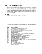
...future use . This code is useful for debug. CF D0 - Input devices: Keyboard/Mouse. 9F is an unrecoverable error. Displaying the POST-codes requires a PCI bus add-in hexadecimal. Output Devices: All output consoles. 7F is an unrecoverable error. Boot Devices: Includes fixed... media and removable media. Reserved for future use (new input console codes). Intel Desktop Board D945GCCR Technical Product Specification 4.4 Port 80h POST Codes During the POST, the BIOS generates diagnostic progress codes (POST-codes) to I /O Busses: PCI, USB, ISA, ATA, etc. 5F is an ...
...future use . This code is useful for debug. CF D0 - Input devices: Keyboard/Mouse. 9F is an unrecoverable error. Displaying the POST-codes requires a PCI bus add-in hexadecimal. Output Devices: All output consoles. 7F is an unrecoverable error. Boot Devices: Includes fixed... media and removable media. Reserved for future use (new input console codes). Intel Desktop Board D945GCCR Technical Product Specification 4.4 Port 80h POST Codes During the POST, the BIOS generates diagnostic progress codes (POST-codes) to I /O Busses: PCI, USB, ISA, ATA, etc. 5F is an ...
Product Specification
Page 79
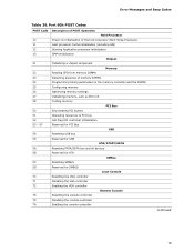
... 23 24 25 26 27 28 50 51 52 53 - 57 58 59 5A 5B 5C 5D 70 71 72 78 79 7A Description of POST Operation Host Processor Power-on initialization of the host processor (Boot Strap Processor) Host processor Cache initialization (including APs) Starting Application processor initialization SMM initialization...
... 23 24 25 26 27 28 50 51 52 53 - 57 58 59 5A 5B 5C 5D 70 71 72 78 79 7A Description of POST Operation Host Processor Power-on initialization of the host processor (Boot Strap Processor) Host processor Cache initialization (including APs) Starting Application processor initialization SMM initialization...

Product Specification
Page 80
... 93 94 95 98 99 9A 9B B0 B1 B2 B3 B8 B9 BA BC Dy E0 E2 E1, E3 E4 E5 E6 Description of POST Operation Keyboard (PS2 or USB) Resetting keyboard Disabling keyboard Detecting presence of keyboard Enabling keyboard Clearing keyboard input buffer Instructing keyboard controller to run Self... first report of EFI_SW_PC_INIT_BEGIN EFI_SW_PEI_PC_HANDOFF_TO_NEXT) Permanent memory found Reserved for PEI/PEIMs DXE Core Entered DXE phase Started dispatching drivers Started connecting drivers continued 80 Intel Desktop Board D945GCCR Technical Product Specification Table 39.
... 93 94 95 98 99 9A 9B B0 B1 B2 B3 B8 B9 BA BC Dy E0 E2 E1, E3 E4 E5 E6 Description of POST Operation Keyboard (PS2 or USB) Resetting keyboard Disabling keyboard Detecting presence of keyboard Enabling keyboard Clearing keyboard input buffer Instructing keyboard controller to run Self... first report of EFI_SW_PC_INIT_BEGIN EFI_SW_PEI_PC_HANDOFF_TO_NEXT) Permanent memory found Reserved for PEI/PEIMs DXE Core Entered DXE phase Started dispatching drivers Started connecting drivers continued 80 Intel Desktop Board D945GCCR Technical Product Specification Table 39.

Product Specification
Page 81
... E7 E8 E9 EB F4 F5 F8 F9 FA 30 31 34 35 3F Description of POST Operation DXE Drivers Waiting for user input Checking password Entering BIOS setup Calling Legacy Option ROMs Runtime Phase/EFI OS Boot Entering Sleep state Exiting ...
... E7 E8 E9 EB F4 F5 F8 F9 FA 30 31 34 35 3F Description of POST Operation DXE Drivers Waiting for user input Checking password Entering BIOS setup Calling Legacy Option ROMs Runtime Phase/EFI OS Boot Entering Sleep state Exiting ...

Product Specification
Page 82
Typical Port 80h POST Sequence POST Code 21 22 23 25 28 34 E4 12 13 50 51 92 90 94 95 EB 58 5A 92 90 94 5A 28 90 ... Resetting PATA/SATA bus and all devices Testing memory Resetting keyboard Clearing keyboard input buffer Waiting for user input INT 19 Ready to boot 82 Intel Desktop Board D945GCCR Technical Product Specification Table 40.
Typical Port 80h POST Sequence POST Code 21 22 23 25 28 34 E4 12 13 50 51 92 90 94 95 EB 58 5A 92 90 94 5A 28 90 ... Resetting PATA/SATA bus and all devices Testing memory Resetting keyboard Clearing keyboard input buffer Waiting for user input INT 19 Ready to boot 82 Intel Desktop Board D945GCCR Technical Product Specification Table 40.
Intel Desktop Board D945GCCR Product Guide English
Page 18
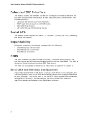
...the BIOS automatically detects and configures the device for your computer, the auto-configuration utility in the BIOS Setup program. 18 Intel Desktop Board D945GCCR Product Guide Enhanced IDE Interface The desktop board's IDE interface handles the exchange of information between the processor and peripheral devices ...Express x16 connector • One PCI Express x1 connector • Two PCI bus connectors BIOS The BIOS provides the Power-On Self-Test (POST), the BIOS Setup program, the PCI/PCI Express and IDE auto-configuration utilities, and the video BIOS. The BIOS is stored in Chapter...
...the BIOS automatically detects and configures the device for your computer, the auto-configuration utility in the BIOS Setup program. 18 Intel Desktop Board D945GCCR Product Guide Enhanced IDE Interface The desktop board's IDE interface handles the exchange of information between the processor and peripheral devices ...Express x16 connector • One PCI Express x1 connector • Two PCI bus connectors BIOS The BIOS provides the Power-On Self-Test (POST), the BIOS Setup program, the PCI/PCI Express and IDE auto-configuration utilities, and the video BIOS. The BIOS is stored in Chapter...
Intel Desktop Board D945GCCR Product Guide English
Page 23
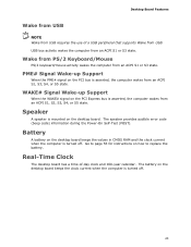
... from an ACPI S1, S2, S3, S4, or S5 state. The speaker provides audible error code (beep code) information during the Power-On Self-Test (POST). WAKE# Signal Wake-up Support When the PME# signal on the desktop board keeps the values in CMOS RAM and the clock current when the...
... from an ACPI S1, S2, S3, S4, or S5 state. The speaker provides audible error code (beep code) information during the Power-On Self-Test (POST). WAKE# Signal Wake-up Support When the PME# signal on the desktop board keeps the values in CMOS RAM and the clock current when the...

Intel Desktop Board D945GCCR Product Guide English
Page 52
...-Test (POST) runs, the BIOS displays the Maintenance Menu. Jumper Settings for the BIOS Setup Program Modes Jumper Setting Mode Normal (default) (1-2) Description The BIOS uses the current configuration and passwords for the BIOS Setup program modes. The BIOS recovers data in the BIOS Setup program. Table 10. Intel Desktop Board D945GCCR Product...
...-Test (POST) runs, the BIOS displays the Maintenance Menu. Jumper Settings for the BIOS Setup Program Modes Jumper Setting Mode Normal (default) (1-2) Description The BIOS uses the current configuration and passwords for the BIOS Setup program modes. The BIOS recovers data in the BIOS Setup program. Table 10. Intel Desktop Board D945GCCR Product...
Intel Desktop Board D945GCCR Product Guide English
Page 61
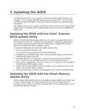
...; Express BIOS Update Utility With the Intel Express BIOS Update utility you how to your hard drive where it was saved. Download the file to update the BIOS by pressing the key after the Power-On Self-Test (POST) memory test begins and before the operating system boot begins. This step...to recover the BIOS if an update fails. Go to the D945GCCR page, click "[view] Latest BIOS updates," and select the Express BIOS Update utility file. 3. This is useful if you can update the system BIOS from the location on the Intel World Wide Web site provides a simple method for multiple identical...
...; Express BIOS Update Utility With the Intel Express BIOS Update utility you how to your hard drive where it was saved. Download the file to update the BIOS by pressing the key after the Power-On Self-Test (POST) memory test begins and before the operating system boot begins. This step...to recover the BIOS if an update fails. Go to the D945GCCR page, click "[view] Latest BIOS updates," and select the Express BIOS Update utility file. 3. This is useful if you can update the system BIOS from the location on the Intel World Wide Web site provides a simple method for multiple identical...


