
Product Specification
Page 5
... IDE Support 24 1.5.4 Real-Time Clock, CMOS SRAM, and Battery 25 1.6 PCI Express* Connectors 25 1.7 Legacy I/O Controller 26 1.7.1 Serial Port 26 1.7.2 Parallel Port 26 1.7.3 Diskette Drive Controller 26 1.7.4 Keyboard and Mouse Interface 26 1.8 Audio Subsystem 27 1.8.1 Audio Subsystem Software 27 1.8.2 Audio Connectors 27 1.8.3 6-Channel (5.1) Audio Subsystem 28 1.9 LAN Subsystem 29 1.9.1 LAN Subsystem Software 29 1.9.2 Intel® 82562G Physical Layer Interface Device 29 1.10 Hardware Management Subsystem 31 1.10.1 Hardware Monitoring and Fan Control ASIC 31 1.10.2 Chassis...
... IDE Support 24 1.5.4 Real-Time Clock, CMOS SRAM, and Battery 25 1.6 PCI Express* Connectors 25 1.7 Legacy I/O Controller 26 1.7.1 Serial Port 26 1.7.2 Parallel Port 26 1.7.3 Diskette Drive Controller 26 1.7.4 Keyboard and Mouse Interface 26 1.8 Audio Subsystem 27 1.8.1 Audio Subsystem Software 27 1.8.2 Audio Connectors 27 1.8.3 6-Channel (5.1) Audio Subsystem 28 1.9 LAN Subsystem 29 1.9.1 LAN Subsystem Software 29 1.9.2 Intel® 82562G Physical Layer Interface Device 29 1.10 Hardware Management Subsystem 31 1.10.1 Hardware Monitoring and Fan Control ASIC 31 1.10.2 Chassis...
Product Specification
Page 6
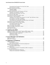
... PCI IDE Support 71 3.4 System Management BIOS (SMBIOS 71 3.5 BIOS Updates 72 3.5.1 Language Support 72 3.5.2 Custom Splash Screen 72 3.6 Legacy USB Support 73 3.7 Boot Options 73 3.7.1 CD-ROM Boot 73 3.7.2 Network Boot 73 3.7.3 Booting Without Attached Devices 74 3.7.4 Changing the Default Boot Device During POST 74 3.8 Adjusting Boot Speed 75 3.8.1 Peripheral Selection and Configuration 75 3.8.2 BIOS Boot Optimizations 75 3.9 BIOS Security Features 76 4 Error Messages and Beep Codes 4.1 Speaker 77 4.2 BIOS Beep Codes 77 4.3 BIOS Error Messages 77 4.4 Port 80h POST Codes...
... PCI IDE Support 71 3.4 System Management BIOS (SMBIOS 71 3.5 BIOS Updates 72 3.5.1 Language Support 72 3.5.2 Custom Splash Screen 72 3.6 Legacy USB Support 73 3.7 Boot Options 73 3.7.1 CD-ROM Boot 73 3.7.2 Network Boot 73 3.7.3 Booting Without Attached Devices 74 3.7.4 Changing the Default Boot Device During POST 74 3.8 Adjusting Boot Speed 75 3.8.1 Peripheral Selection and Configuration 75 3.8.2 BIOS Boot Optimizations 75 3.9 BIOS Security Features 76 4 Error Messages and Beep Codes 4.1 Speaker 77 4.2 BIOS Beep Codes 77 4.3 BIOS Error Messages 77 4.4 Port 80h POST Codes...
Product Specification
Page 8
... Front Panel Power/Sleep LED Header 54 24. States for a Two-Color Power LED 56 27. Fan Header Current Capability 63 30. Product Certification Markings 90 viii Front and Rear Chassis Fan Headers 52 21. Typical Port 80h POST Sequence 82 41. Intel Desktop Board D945GCCR Technical Product Specification 15. Environmental Specifications 67 32. Serial ATA Connectors 52 19. Front Panel Audio Header 52 17. Lead-Free Board Markings 88 43. BIOS Setup Program Menu Bar 70 33. Port 80h POST Codes 79...
... Front Panel Power/Sleep LED Header 54 24. States for a Two-Color Power LED 56 27. Fan Header Current Capability 63 30. Product Certification Markings 90 viii Front and Rear Chassis Fan Headers 52 21. Typical Port 80h POST Sequence 82 41. Intel Desktop Board D945GCCR Technical Product Specification 15. Environmental Specifications 67 32. Serial ATA Connectors 52 19. Front Panel Audio Header 52 17. Lead-Free Board Markings 88 43. BIOS Setup Program Menu Bar 70 33. Port 80h POST Codes 79...
Product Specification
Page 45
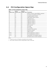
... when a PCI Express x16 graphics card is dynamic and can change based on add-in cards used. 45 Bus number is installed. 2. PCI Configuration Space Map Bus Device Function Number (hex) Number (hex) Number (hex) Description 00 00 00 Memory controller of Intel 82945GC component 00 01 00 PCI Express x16 graphics port (Note 1) 00 02 00 Integrated graphics controller 00 1B 00 High Definition Audio Controller 00 1C 00 PCI Express port 1 00 1D 00 USB UHCI controller 1 00...
... when a PCI Express x16 graphics card is dynamic and can change based on add-in cards used. 45 Bus number is installed. 2. PCI Configuration Space Map Bus Device Function Number (hex) Number (hex) Number (hex) Description 00 00 00 Memory controller of Intel 82945GC component 00 01 00 PCI Express x16 graphics port (Note 1) 00 02 00 Integrated graphics controller 00 1B 00 High Definition Audio Controller 00 1C 00 PCI Express port 1 00 1D 00 USB UHCI controller 1 00...
Product Specification
Page 48
... the computer's chassis. The other internal connectors/headers are not overcurrent protected and should connect only to devices inside the computer's chassis, such as fans and internal peripherals. The connectors and headers can be divided into these connectors/headers to power devices external to the computer, the power cable, and the external devices themselves. Intel Desktop Board D945GCCR Technical Product Specification 2.7 Connectors and Headers CAUTION Only the following connectors have overcurrent protection: back panel USB, front panel USB, and PS...
... the computer's chassis. The other internal connectors/headers are not overcurrent protected and should connect only to devices inside the computer's chassis, such as fans and internal peripherals. The connectors and headers can be divided into these connectors/headers to power devices external to the computer, the power cable, and the external devices themselves. Intel Desktop Board D945GCCR Technical Product Specification 2.7 Connectors and Headers CAUTION Only the following connectors have overcurrent protection: back panel USB, front panel USB, and PS...

Product Specification
Page 69
..., POST, the PCI auto-configuration utility, and Plug and Play support. The BIOS displays a message during POST identifying the type of BIOS Features What This Chapter Contains 3.1 Introduction 69 3.2 BIOS Flash Memory Organization 70 3.3 Resource Configuration 70 3.4 System Management BIOS (SMBIOS 71 3.5 BIOS Updates 72 3.6 Legacy USB Support 73 3.7 Boot Options 73 3.8 Adjusting Boot Speed 75 3.9 BIOS Security Features 76 3.1 Introduction The boards use an Intel BIOS that is powered-up, the BIOS compares the CPU version and the microcode version in configure mode. The BIOS...
..., POST, the PCI auto-configuration utility, and Plug and Play support. The BIOS displays a message during POST identifying the type of BIOS Features What This Chapter Contains 3.1 Introduction 69 3.2 BIOS Flash Memory Organization 70 3.3 Resource Configuration 70 3.4 System Management BIOS (SMBIOS 71 3.5 BIOS Updates 72 3.6 Legacy USB Support 73 3.7 Boot Options 73 3.8 Adjusting Boot Speed 75 3.9 BIOS Security Features 76 3.1 Introduction The boards use an Intel BIOS that is powered-up, the BIOS compares the CPU version and the microcode version in configure mode. The BIOS...
Product Specification
Page 70
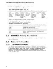
... PCI devices. Any interrupts set to Available in Setup are considered to Setup program options Table 33 lists the function keys available for menu screens. Table 32. BIOS Setup Program Menu Bar Maintenance Clears passwords and displays processor information Main Advanced Displays processor and memory configuration Configures advanced features available through the chipset Security Sets passwords and security features Power Boot Configures power management features and power supply controls Selects boot options Exit Saves or discards changes to be onboard or add-in card...
... PCI devices. Any interrupts set to Available in Setup are considered to Setup program options Table 33 lists the function keys available for menu screens. Table 32. BIOS Setup Program Menu Bar Maintenance Clears passwords and displays processor information Main Advanced Displays processor and memory configuration Configures advanced features available through the chipset Security Sets passwords and security features Power Boot Configures power management features and power supply controls Selects boot options Exit Saves or discards changes to be onboard or add-in card...
Product Specification
Page 71
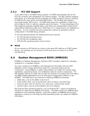
... hard drive as Windows NT*, require an additional interface for managing computers in the BIOS Setup program. To take advantage of each drive and configures them to PIO Mode 3 or 4, depending on a non-Plug and Play operating system can obtain the system types, capabilities, operational status, and installation dates for system components. The interface also supports second-generation SATA drives. The IDE interface supports hard drives up the PCI IDE connector...
... hard drive as Windows NT*, require an additional interface for managing computers in the BIOS Setup program. To take advantage of each drive and configures them to PIO Mode 3 or 4, depending on a non-Plug and Play operating system can obtain the system types, capabilities, operational status, and installation dates for system components. The interface also supports second-generation SATA drives. The IDE interface supports hard drives up the PCI IDE connector...
Product Specification
Page 73
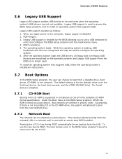
... Legacy USB support from a diskette drive, hard drives, CD-ROM, or the network. After the operating system loads the USB drivers, all legacy and non-legacy USB devices are recognized and may be used to configure the operating system. 6. Boot devices are not yet available. To use a USB keyboard to enter and configure the BIOS Setup program and the maintenance menu. 4. The operating system loads. To install an operating system that supports USB. When you to use this key during POST automatically forces booting from...
... Legacy USB support from a diskette drive, hard drives, CD-ROM, or the network. After the operating system loads the USB drivers, all legacy and non-legacy USB devices are recognized and may be used to configure the operating system. 6. Boot devices are not yet available. To use a USB keyboard to enter and configure the BIOS Setup program and the maintenance menu. 4. The operating system loads. To install an operating system that supports USB. When you to use this key during POST automatically forces booting from...
Product Specification
Page 78
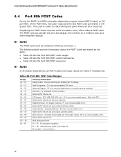
Displaying the POST-codes requires a PCI bus add-in PCI bus connector 1. Table 38. AF B0 - Memory/Chipset: 2F is an unrecoverable error. Reserved for determining the point where an error occurred. Boot Devices: Includes fixed media and removable media. BF is no memory detected or no useful memory detected. Boot device selection. F0 - E0 - See Table 39. This code is left at port 80h. Port 80h POST Code Ranges Range 00 - 0F 10 - 1F 20...
Displaying the POST-codes requires a PCI bus add-in PCI bus connector 1. Table 38. AF B0 - Memory/Chipset: 2F is an unrecoverable error. Reserved for determining the point where an error occurred. Boot Devices: Includes fixed media and removable media. BF is no memory detected or no useful memory detected. Boot device selection. F0 - E0 - See Table 39. This code is left at port 80h. Port 80h POST Code Ranges Range 00 - 0F 10 - 1F 20...
Product Specification
Page 79
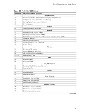
... the memory controller and the DIMMs Configuring memory Optimizing memory settings Initializing memory, such as ECC init Testing memory PCI Bus Enumerating PCI busses Allocating resources to PCI bus Hot Plug PCI controller initialization Reserved for PCI Bus USB Resetting USB bus Reserved for USB ATA/ATAPI/SATA Resetting PATA/SATA bus and all devices Reserved for ATA SMBus Resetting SMBUS Reserved for SMBUS Local Console Resetting the VGA controller Disabling the VGA controller Enabling the VGA controller Remote Console Resetting the console controller Disabling the console controller Enabling...
... the memory controller and the DIMMs Configuring memory Optimizing memory settings Initializing memory, such as ECC init Testing memory PCI Bus Enumerating PCI busses Allocating resources to PCI bus Hot Plug PCI controller initialization Reserved for PCI Bus USB Resetting USB bus Reserved for USB ATA/ATAPI/SATA Resetting PATA/SATA bus and all devices Reserved for ATA SMBus Resetting SMBUS Reserved for SMBUS Local Console Resetting the VGA controller Disabling the VGA controller Enabling the VGA controller Remote Console Resetting the console controller Disabling the console controller Enabling...
Intel Desktop Board D945GCCR Product Guide English
Page 3
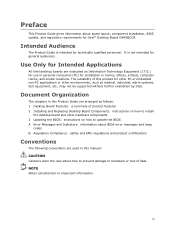
... about BIOS error messages and beep codes B Regulatory Compliance: safety and EMC regulations and product certifications Conventions The following conventions are evaluated as medical, industrial, alarm systems, test equipment, etc., may not be supported without further evaluation by Intel. Document Organization The chapters in this product for Intel® Desktop Board D945GCCR. Preface This Product Guide gives information about board layout, component installation, BIOS update, and...
... about BIOS error messages and beep codes B Regulatory Compliance: safety and EMC regulations and product certifications Conventions The following conventions are evaluated as medical, industrial, alarm systems, test equipment, etc., may not be supported without further evaluation by Intel. Document Organization The chapters in this product for Intel® Desktop Board D945GCCR. Preface This Product Guide gives information about board layout, component installation, BIOS update, and...
Intel Desktop Board D945GCCR Product Guide English
Page 6
...Removing the PCI Express x16 Card 40 Connecting the IDE Cable 41 Connecting the Serial ATA (SATA) Cable 42 Connecting to Internal Headers 43 Installing a Front Panel Audio Solution for Intel® High Definition Audio 44 Connecting to the USB 2.0 Headers 45 Connecting to the Front Panel Header 45 Connecting to the Alternate Front Panel Power LED Header 46 Connecting to the Flexible Audio System 47 Connecting Chassis Fan and Power Cables 48 Connecting Chassis Fan Cables 48 Connecting Power Cables 49 Other Connectors and Headers 50 Setting the BIOS Configuration Jumper 51 Clearing...
...Removing the PCI Express x16 Card 40 Connecting the IDE Cable 41 Connecting the Serial ATA (SATA) Cable 42 Connecting to Internal Headers 43 Installing a Front Panel Audio Solution for Intel® High Definition Audio 44 Connecting to the USB 2.0 Headers 45 Connecting to the Front Panel Header 45 Connecting to the Alternate Front Panel Power LED Header 46 Connecting to the Flexible Audio System 47 Connecting Chassis Fan and Power Cables 48 Connecting Chassis Fan Cables 48 Connecting Power Cables 49 Other Connectors and Headers 50 Setting the BIOS Configuration Jumper 51 Clearing...
Intel Desktop Board D945GCCR Product Guide English
Page 7
... Figures 1. Desktop Board D945GCCR Components 11 2. Desktop Board D945GCCR Mounting Screw Hole Locations 29 6. Close the Load Plate 33 12. Use DDR2 DIMMs 36 15. Connecting the Serial ATA Cable 42 20. Location of the Other Connectors and Headers 50 25. Alternate Front Panel Power LED Header 46 10. Jumper Settings for Intel High Definition Audio 44 6. Dual Channel Memory Configuration Example 35 14. Back Panel Audio Connectors 47 22. Feature Summary 9 2. Beep Codes 63 12. LAN Connector LEDs 17 3. Back Panel Connectors 54 27. BIOS Error Messages...
... Figures 1. Desktop Board D945GCCR Components 11 2. Desktop Board D945GCCR Mounting Screw Hole Locations 29 6. Close the Load Plate 33 12. Use DDR2 DIMMs 36 15. Connecting the Serial ATA Cable 42 20. Location of the Other Connectors and Headers 50 25. Alternate Front Panel Power LED Header 46 10. Jumper Settings for Intel High Definition Audio 44 6. Dual Channel Memory Configuration Example 35 14. Back Panel Audio Connectors 47 22. Feature Summary 9 2. Beep Codes 63 12. LAN Connector LEDs 17 3. Back Panel Connectors 54 27. BIOS Error Messages...
Intel Desktop Board D945GCCR Product Guide English
Page 9
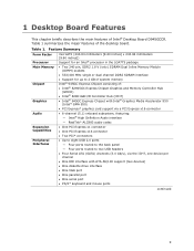
... to two USB headers • Four Serial ATA (SATA) channels (3.0 Gb/s), via the ICH7, one device per channel • One IDE interface with ATA-66/100 support (two devices) • One diskette drive interface • One VGA port • One parallel port • One serial port • PS/2* keyboard and mouse ports continued 9 Table 1. 1 Desktop Board Features This chapter briefly describes the main features of : • Intel® 82945GC Express Chipset Graphics and Memory Controller Hub (GMCH...
... to two USB headers • Four Serial ATA (SATA) channels (3.0 Gb/s), via the ICH7, one device per channel • One IDE interface with ATA-66/100 support (two devices) • One diskette drive interface • One VGA port • One parallel port • One serial port • PS/2* keyboard and mouse ports continued 9 Table 1. 1 Desktop Board Features This chapter briefly describes the main features of : • Intel® 82945GC Express Chipset Graphics and Memory Controller Hub (GMCH...

Intel Desktop Board D945GCCR Product Guide English
Page 12
...Front panel audio header PCI bus connector 2 PCI bus connector 1 PCI Express x1 connector PCI Express x16 connector Back panel connectors 12 V processor core voltage connector (2 x 2 pin ) Processor fan header (4-pin) Rear chassis fan header (3-pin) Processor socket DIMM 0, Channel A socket DIMM 0, Channel B socket Chassis intrusion header Main power connector (2 x 12 pin) Diskette drive connector IDE connector Front chassis fan header (3-pin) Serial ATA connectors Front panel header Speaker Hi-speed USB 2.0 headers Alternate front panel power LED header Battery BIOS configuration jumper block...
...Front panel audio header PCI bus connector 2 PCI bus connector 1 PCI Express x1 connector PCI Express x16 connector Back panel connectors 12 V processor core voltage connector (2 x 2 pin ) Processor fan header (4-pin) Rear chassis fan header (3-pin) Processor socket DIMM 0, Channel A socket DIMM 0, Channel B socket Chassis intrusion header Main power connector (2 x 12 pin) Diskette drive connector IDE connector Front chassis fan header (3-pin) Serial ATA connectors Front panel header Speaker Hi-speed USB 2.0 headers Alternate front panel power LED header Battery BIOS configuration jumper block...
Intel Desktop Board D945GCCR Product Guide English
Page 18
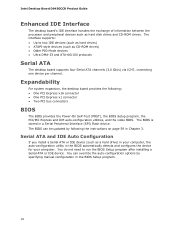
... two IDE devices (such as hard drives) • ATAPI-style devices (such as hard disk drives and CD-ROM drives. Intel Desktop Board D945GCCR Product Guide Enhanced IDE Interface The desktop board's IDE interface handles the exchange of information between the processor and peripheral devices such as CD-ROM drives) • Older PIO Mode devices • Ultra DMA-33 and ATA-66/100 protocols Serial ATA The desktop board supports four Serial ATA channels (3.0 Gb/s) via ICH7, connecting one device per channel. The BIOS is...
... two IDE devices (such as hard drives) • ATAPI-style devices (such as hard disk drives and CD-ROM drives. Intel Desktop Board D945GCCR Product Guide Enhanced IDE Interface The desktop board's IDE interface handles the exchange of information between the processor and peripheral devices such as CD-ROM drives) • Older PIO Mode devices • Ultra DMA-33 and ATA-66/100 protocols Serial ATA The desktop board supports four Serial ATA channels (3.0 Gb/s) via ICH7, connecting one device per channel. The BIOS is...

Intel Desktop Board D945GCCR Product Guide English
Page 20
... 24 on the desktop board. The computer's response can be connected to the power state it was in the BIOS Setup program's Boot menu. The security feature uses a mechanical switch on the chassis that can turn off ). Power Management Features Power management is implemented at several levels, including: • Software support through system control. Power Connectors ATX12V-compliant power supplies can be set by using the Last Power State feature in before power was interrupted...
... 24 on the desktop board. The computer's response can be connected to the power state it was in the BIOS Setup program's Boot menu. The security feature uses a mechanical switch on the chassis that can turn off ). Power Management Features Power management is implemented at several levels, including: • Software support through system control. Power Connectors ATX12V-compliant power supplies can be set by using the Last Power State feature in before power was interrupted...
Intel Desktop Board D945GCCR Product Guide English
Page 21
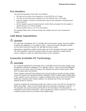
... desktop board has a 4-pin processor fan header and two 3-pin chassis fan headers. LAN wakeup capabilities enable remote wake-up of delivering adequate +5 V standby current. Failure to a tachometer input of the hardware monitoring and control device. • All fan headers support closed-loop fan control that powers up device or event, the computer quickly returns to be capable of delivering adequate +5 V standby current. If the computer has a dual-colored power LED on the front panel, the sleep state is wired...
... desktop board has a 4-pin processor fan header and two 3-pin chassis fan headers. LAN wakeup capabilities enable remote wake-up of delivering adequate +5 V standby current. Failure to a tachometer input of the hardware monitoring and control device. • All fan headers support closed-loop fan control that powers up device or event, the computer quickly returns to be capable of delivering adequate +5 V standby current. If the computer has a dual-colored power LED on the front panel, the sleep state is wired...

Intel Desktop Board D945GCCR Product Guide English
Page 53
... boot. 7. Turn off all peripheral devices connected to normal mode. 1. Place the jumper on pins 1-2 as shown below . 13. Installing and Replacing Desktop Board Components Clearing Passwords This procedure assumes that you confirm clearing the password. Disconnect the computer's power cord from the AC power source. 11. Find the configuration jumper block (see Figure 25). 5. Select Yes and press . The computer starts the Setup program. Turn off the computer. Remove the computer cover. 4. Use...
... boot. 7. Turn off all peripheral devices connected to normal mode. 1. Place the jumper on pins 1-2 as shown below . 13. Installing and Replacing Desktop Board Components Clearing Passwords This procedure assumes that you confirm clearing the password. Disconnect the computer's power cord from the AC power source. 11. Find the configuration jumper block (see Figure 25). 5. Select Yes and press . The computer starts the Setup program. Turn off the computer. Remove the computer cover. 4. Use...


