Product Guide
Page 3
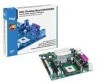
... manual: WARNING Warnings indicate conditions that, if not observed, can cause personal injury. Preface This Product Guide gives information about board layout, component installation, BIOS Setup menus, and regulatory requirements for Intel® Desktop Board D845GVSR. Intended Audience The Product Guide is not intended for technically qualified personnel. Information Layout The chapters in this Product Guide...
... manual: WARNING Warnings indicate conditions that, if not observed, can cause personal injury. Preface This Product Guide gives information about board layout, component installation, BIOS Setup menus, and regulatory requirements for Intel® Desktop Board D845GVSR. Intended Audience The Product Guide is not intended for technically qualified personnel. Information Layout The chapters in this Product Guide...
Product Guide
Page 5
...Desktop Board Features Desktop Board Components 11 Processor ...13 Main Memory ...14 Intel® 845GV Chipset ...15 Audio Subsystem ...15 LAN Subsystem (Optional 16 LAN Subsystem Software 16 RJ-45 LAN Connector LEDs 16 Hi-Speed USB 2.0 Support 16 Enhanced IDE Interface ...17 Expansion Slots...17 BIOS... ...17 PCI Auto Configuration 17 IDE Auto Configuration 17 Security Passwords ...18 Power Management Features 18 Speaker...20 Battery...20 Real-Time Clock...20 2 Installing and Replacing Desktop Board Components Before You Begin ...21 Installation...
...Desktop Board Features Desktop Board Components 11 Processor ...13 Main Memory ...14 Intel® 845GV Chipset ...15 Audio Subsystem ...15 LAN Subsystem (Optional 16 LAN Subsystem Software 16 RJ-45 LAN Connector LEDs 16 Hi-Speed USB 2.0 Support 16 Enhanced IDE Interface ...17 Expansion Slots...17 BIOS... ...17 PCI Auto Configuration 17 IDE Auto Configuration 17 Security Passwords ...18 Power Management Features 18 Speaker...20 Battery...20 Real-Time Clock...20 2 Installing and Replacing Desktop Board Components Before You Begin ...21 Installation...
Product Guide
Page 6
Intel Desktop Board D845GVSR Product Guide Connecting Add-In Card and Peripheral Interface Connectors 36 Setting the BIOS Configuration Jumper Block 37 Clearing Passwords ...38 Back Panel Connectors ...39 Replacing the Battery ...40 3 Updating the BIOS Updating the BIOS with the Intel® Express BIOS Update Utility 45 Updating the BIOS with the Intel® Iflash BIOS Update Utility 45 Obtaining the BIOS... 73 Exit Menu ...74 5 Desktop Board Resources Memory Map ...75 DMA Channels ...75 Interrupts ...76 A Error Messages and Indicators BIOS Beep Codes ...77 BIOS Error Messages ...78 vi
Intel Desktop Board D845GVSR Product Guide Connecting Add-In Card and Peripheral Interface Connectors 36 Setting the BIOS Configuration Jumper Block 37 Clearing Passwords ...38 Back Panel Connectors ...39 Replacing the Battery ...40 3 Updating the BIOS Updating the BIOS with the Intel® Express BIOS Update Utility 45 Updating the BIOS with the Intel® Iflash BIOS Update Utility 45 Obtaining the BIOS... 73 Exit Menu ...74 5 Desktop Board Resources Memory Map ...75 DMA Channels ...75 Interrupts ...76 A Error Messages and Indicators BIOS Beep Codes ...77 BIOS Error Messages ...78 vi
Product Guide
Page 7
... 19 3. Removing the Battery from the Desktop Board 43 vii Connecting the IDE Cable 30 9. Back Panel Connectors 39 14. Installing a Processor...26 6. Internal Headers ...31 10. Desktop Board Components 11 2. Connecting the Processor Fan Heatsink Cable to the Processor Fan Header 27 7. Installing Memory...28 8. Location of the BIOS Configuration Jumper Block 37 13.
... 19 3. Removing the Battery from the Desktop Board 43 vii Connecting the IDE Cable 30 9. Back Panel Connectors 39 14. Installing a Processor...26 6. Internal Headers ...31 10. Desktop Board Components 11 2. Connecting the Processor Fan Heatsink Cable to the Processor Fan Header 27 7. Installing Memory...28 8. Location of the BIOS Configuration Jumper Block 37 13.
Product Guide
Page 8
...J8A1 32 8. PCI Configuration Submenu 53 16. ACPI Submenu ...68 28. System Memory Map...75 35. Processors Supported by the Desktop Board 13 4. BIOS Setup Program Function Keys 50 12. IDE Configuration Submenu 57 19. Chipset Configuration Submenu 64 25. Security Menu...66 26. Boot ...60 21. Power Menu...67 27. ATAPI CD-ROM Drives Submenu 73 33. DMA Channels...75 36. Memory Support ...14 5. BIOS Error Messages 78 39. Intel Desktop Board D845GVSR Product Guide Tables 1. RJ-45 LAN Connector LEDs 16 6. USB 2.0 Header (J9F2 33 9. Safety Regulations...81 40. Boot ...
...J8A1 32 8. PCI Configuration Submenu 53 16. ACPI Submenu ...68 28. System Memory Map...75 35. Processors Supported by the Desktop Board 13 4. BIOS Setup Program Function Keys 50 12. IDE Configuration Submenu 57 19. Chipset Configuration Submenu 64 25. Security Menu...66 26. Boot ...60 21. Power Menu...67 27. ATAPI CD-ROM Drives Submenu 73 33. DMA Channels...75 36. Memory Support ...14 5. BIOS Error Messages 78 39. Intel Desktop Board D845GVSR Product Guide Tables 1. RJ-45 LAN Connector LEDs 16 6. USB 2.0 Header (J9F2 33 9. Safety Regulations...81 40. Boot ...
Product Guide
Page 9
...interface • One parallel port • One serial port • One VGA port • PS/2* keyboard and mouse ports • Intel/AMI BIOS • Intel® Rapid BIOS Boot • Intel® Express BIOS Update • SMBIOS support • Support for Advanced Configuration and Power Interface (ACPI) • Hardware support for power, fan, and... mouse, and PME# wakeup. 9 Two ports routed to the USB 2.0 header • Two IDE interfaces with DIMMs utilizing 512 Mbit technology DRAM devices Intel® 845GV chipset, consisting of Intel® Desktop Board D845GVSR. Table 1.
...interface • One parallel port • One serial port • One VGA port • PS/2* keyboard and mouse ports • Intel/AMI BIOS • Intel® Rapid BIOS Boot • Intel® Express BIOS Update • SMBIOS support • Support for Advanced Configuration and Power Interface (ACPI) • Hardware support for power, fan, and... mouse, and PME# wakeup. 9 Two ports routed to the USB 2.0 header • Two IDE interfaces with DIMMs utilizing 512 Mbit technology DRAM devices Intel® 845GV chipset, consisting of Intel® Desktop Board D845GVSR. Table 1.
Product Guide
Page 10
Intel Desktop Board D845GVSR Product Guide ✏ NOTE For information about this Intel desktop board, including the Technical Product Specification (TPS), BIOS updates, and device drivers, go to the Intel World Wide Web site at: http://support.intel.com/support/motherboards/desktop/ Supported Operating Systems The desktop board supports the following operating systems: • Microsoft Windows* 98 SE • Microsoft Windows Me • Microsoft Windows 2000 • Microsoft Windows XP 10
Intel Desktop Board D845GVSR Product Guide ✏ NOTE For information about this Intel desktop board, including the Technical Product Specification (TPS), BIOS updates, and device drivers, go to the Intel World Wide Web site at: http://support.intel.com/support/motherboards/desktop/ Supported Operating Systems The desktop board supports the following operating systems: • Microsoft Windows* 98 SE • Microsoft Windows Me • Microsoft Windows 2000 • Microsoft Windows XP 10

Product Guide
Page 12
Intel Desktop Board D845GVSR Product Guide Table 2. Desktop Board Components Item Description A Front panel audio header B Auxiliary line-in header C CD-in (ATAPI) header D 12 V power connector E... Auxiliary front panel power LED connector P Front chassis fan header Q Chassis intrusion header R BIOS S Front panel header T Front panel USB header U PCI connectors Related Links: Go to the following links for more information about Intel Desktop Board D845GVSR: • http://www.intel.com/design/motherbd • http://support.intel.com/support/motherboards/desktop 12
Intel Desktop Board D845GVSR Product Guide Table 2. Desktop Board Components Item Description A Front panel audio header B Auxiliary line-in header C CD-in (ATAPI) header D 12 V power connector E... Auxiliary front panel power LED connector P Front chassis fan header Q Chassis intrusion header R BIOS S Front panel header T Front panel USB header U PCI connectors Related Links: Go to the following links for more information about Intel Desktop Board D845GVSR: • http://www.intel.com/design/motherbd • http://support.intel.com/support/motherboards/desktop 12
Product Guide
Page 14
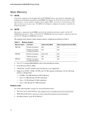
The BIOS will see a notification to 1.0 GB utilizing 256 Mb technology - Memory Support Memory Speed Processor System Bus (MHz) Memory Speed Outcome (MHz) DDR 333 Pentium 4 processor ...://support.intel.com/support/motherboards/desktop/ • SDRAM specifications, http://www.intel.com/technology/memory/pcsdram/spec/ • Installing memory, page 28 in Table 4. Up to 2 GB utilizing 512 MB technology Related Links: Go to 512 MB utilizing 128 Mb technology - Up to this effect on the screen at power up. Table 4. Intel Desktop Board D845GVSR Product Guide...
The BIOS will see a notification to 1.0 GB utilizing 256 Mb technology - Memory Support Memory Speed Processor System Bus (MHz) Memory Speed Outcome (MHz) DDR 333 Pentium 4 processor ...://support.intel.com/support/motherboards/desktop/ • SDRAM specifications, http://www.intel.com/technology/memory/pcsdram/spec/ • Installing memory, page 28 in Table 4. Up to 2 GB utilizing 512 MB technology Related Links: Go to 512 MB utilizing 128 Mb technology - Up to this effect on the screen at power up. Table 4. Intel Desktop Board D845GVSR Product Guide...
Product Guide
Page 16
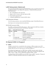
...built into the RJ-45 LAN connector. Disabling Hi-Speed USB in the BIOS reverts all USB 2.0 ports to a USB front panel header. USB 1.1 devices will function normally at : http://support.intel.com/support/motherboards/desktop/ RJ-45 LAN Connector LEDs Two LEDs are backward compatible with the...not meet FCC Class B requirements, even if no device or a low-speed USB device is attached to the D845GVSR link on the LAN. Intel Desktop Board D845GVSR Product Guide LAN Subsystem (Optional) The optional Intel 82562ET (with USB 1.1 devices. On (brighter and pulsing) The computer is selected.
...built into the RJ-45 LAN connector. Disabling Hi-Speed USB in the BIOS reverts all USB 2.0 ports to a USB front panel header. USB 1.1 devices will function normally at : http://support.intel.com/support/motherboards/desktop/ RJ-45 LAN Connector LEDs Two LEDs are backward compatible with the...not meet FCC Class B requirements, even if no device or a low-speed USB device is attached to the D845GVSR link on the LAN. Intel Desktop Board D845GVSR Product Guide LAN Subsystem (Optional) The optional Intel 82562ET (with USB 1.1 devices. On (brighter and pulsing) The computer is selected.
Product Guide
Page 17
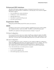
...You do not need to run the BIOS Setup program after you install an IDE device (such as CD-ROM drives) • Older PIO Mode devices • Ultra DMA-33 and ATA-66/100 protocols • Laser Servo (LS-120) drives Expansion Slots Desktop Board D845GVSR has three PCI bus add-in ...card. The BIOS is stored in the BIOS automatically detects and configures the device for that add-in card connectors. You do not need to run the...
...You do not need to run the BIOS Setup program after you install an IDE device (such as CD-ROM drives) • Older PIO Mode devices • Ultra DMA-33 and ATA-66/100 protocols • Laser Servo (LS-120) drives Expansion Slots Desktop Board D845GVSR has three PCI bus add-in ...card. The BIOS is stored in the BIOS automatically detects and configures the device for that add-in card connectors. You do not need to run the...
Product Guide
Page 18
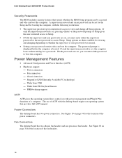
... program can enter either the supervisor password or the user password to view and change all Setup options. Intel Desktop Board D845GVSR Product Guide Security Passwords The BIOS includes security features that provides full ACPI support. If only the supervisor password is booted. See Figure 10 on whether the supervisor or user password ...
... program can enter either the supervisor password or the user password to view and change all Setup options. Intel Desktop Board D845GVSR Product Guide Security Passwords The BIOS includes security features that provides full ACPI support. If only the supervisor password is booted. See Figure 10 on whether the supervisor or user password ...
Product Guide
Page 21
...or modems before performing any procedures can continue to operate even though the front panel power button is off. 2 Installing and Replacing Desktop Board Components This chapter tells you open the computer or perform any of the midboard and front panel connectors provide operating voltage (+5 V dc... headers • Connect hardware control and power cables • Connect add-in card and peripheral interface connectors • Set the BIOS configuration jumper block • Clear passwords • Connect back panel connectors • Replace the battery Before You Begin WARNINGS The procedures ...
...or modems before performing any procedures can continue to operate even though the front panel power button is off. 2 Installing and Replacing Desktop Board Components This chapter tells you open the computer or perform any of the midboard and front panel connectors provide operating voltage (+5 V dc... headers • Connect hardware control and power cables • Connect add-in card and peripheral interface connectors • Set the BIOS configuration jumper block • Clear passwords • Connect back panel connectors • Replace the battery Before You Begin WARNINGS The procedures ...
Product Guide
Page 37
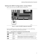
... the jumper settings for booting. 31 Configure (2-3) After the Power-On Self-Test (POST) runs, the BIOS displays the Maintenance Menu. Table 9. Installing and Replacing Desktop Board Components Setting the BIOS Configuration Jumper Block Figure 12 shows the location of a failed BIOS update. 37 Use this menu to be done in the event of the...
... the jumper settings for booting. 31 Configure (2-3) After the Power-On Self-Test (POST) runs, the BIOS displays the Maintenance Menu. Table 9. Installing and Replacing Desktop Board Components Setting the BIOS Configuration Jumper Block Figure 12 shows the location of a failed BIOS update. 37 Use this menu to be done in the event of the...

Product Guide
Page 40
..., the battery has an estimated life of three years. Batterier bør om muligt genbruges. When the voltage drops below a certain level, the BIOS Setup program settings stored in accordance with an incorrect type. Batteries should be accurate. La mise au rebut des piles usagées doit respecter... the computer is accurate to ± 13 minutes/year at 25 ºC with an equivalent one. Replace the battery with 3.3 VSB applied. Intel Desktop Board D845GVSR Product Guide Replacing the Battery A coin-cell battery (CR2032) powers the real-time clock and CMOS memory.
..., the battery has an estimated life of three years. Batterier bør om muligt genbruges. When the voltage drops below a certain level, the BIOS Setup program settings stored in accordance with an incorrect type. Batteries should be accurate. La mise au rebut des piles usagées doit respecter... the computer is accurate to ± 13 minutes/year at 25 ºC with an equivalent one. Replace the battery with 3.3 VSB applied. Intel Desktop Board D845GVSR Product Guide Replacing the Battery A coin-cell battery (CR2032) powers the real-time clock and CMOS memory.
Product Guide
Page 45
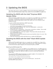
... D845GVSR page, click "[view] Latest BIOS updates", and select the Intel Iflash BIOS Update utility file. 45 Updating the BIOS with the Intel® Express BIOS Update Utility With the Intel Express BIOS Update utility you can update the system BIOS while in an automated update utility that will be rebooted at : http://support.intel.com/support/motherboards/desktop/ Navigate to complete the BIOS...
... D845GVSR page, click "[view] Latest BIOS updates", and select the Intel Iflash BIOS Update utility file. 45 Updating the BIOS with the Intel® Express BIOS Update Utility With the Intel Express BIOS Update utility you can update the system BIOS while in an automated update utility that will be rebooted at : http://support.intel.com/support/motherboards/desktop/ Navigate to complete the BIOS...
Product Guide
Page 46
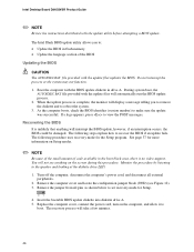
...46 Turn off the computer, disconnect the computer's power cord, and disconnect all pins as shown below to : • Update the BIOS in flash memory • Update the language section of code available in drive A. The recovery process will display a message telling you... 12). 3. The following procedure uses recovery mode for Setup. 31 4. The Intel Iflash BIOS update utility allows you to remove the diskette and to make sure the update was successful. Intel Desktop Board D845GVSR Product Guide ✏ NOTE Review the instructions distributed with the update files will ...
...46 Turn off the computer, disconnect the computer's power cord, and disconnect all pins as shown below to : • Update the BIOS in flash memory • Update the language section of code available in drive A. The recovery process will display a message telling you... 12). 3. The following procedure uses recovery mode for Setup. 31 4. The Intel Iflash BIOS update utility allows you to remove the diskette and to make sure the update was successful. Intel Desktop Board D845GVSR Product Guide ✏ NOTE Review the instructions distributed with the update files will ...
Product Guide
Page 47
... (see page 46). 47 Drive A activity will begin again followed by two more beeps indicating the successful recovery of the BIOS core. On the jumper block (J9H2), reinstall the jumper back on the computer and continue with the following steps. 10. ... are heard and drive A activity ceases (temporarily) indicating the successful recovery of the boot block. This sequence of events indicates a successful BIOS recovery. • A series of continuous beeps indicates a failed BIOS recovery. 7. Listen to the speaker: • Upon applying power, drive A will begin to show activity.
... (see page 46). 47 Drive A activity will begin again followed by two more beeps indicating the successful recovery of the BIOS core. On the jumper block (J9H2), reinstall the jumper back on the computer and continue with the following steps. 10. ... are heard and drive A activity ceases (temporarily) indicating the successful recovery of the boot block. This sequence of events indicates a successful BIOS recovery. • A series of continuous beeps indicates a failed BIOS recovery. 7. Listen to the speaker: • Upon applying power, drive A will begin to show activity.
Product Guide
Page 49
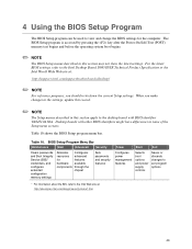
... controls Saves or discards changes to set program options * For information about the BIS, refer to the Intel Web site at : http://support.intel.com/support/motherboards/desktop/ ✏ NOTE For reference purposes, you make changes to the settings, update this record. ✏...Setup menu screens. For the latest BIOS settings, refer to the desktop board with other BIOS identifiers might have differences in this section apply to the Intel Desktop Board D845GVSR Technical Product Specification or the Intel World Wide Web site at : http://developer.intel.com/design/security/index1.htm 49...
... controls Saves or discards changes to set program options * For information about the BIS, refer to the Intel Web site at : http://support.intel.com/support/motherboards/desktop/ ✏ NOTE For reference purposes, you make changes to the settings, update this record. ✏...Setup menu screens. For the latest BIOS settings, refer to the desktop board with other BIOS identifiers might have differences in this section apply to the Intel Desktop Board D845GVSR Technical Product Specification or the Intel World Wide Web site at : http://developer.intel.com/design/security/index1.htm 49...
Product Guide
Page 50
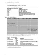
... the BIS, refer to the Intel Web site at: http://developer.intel.com/design/security/index1.htm 50 Table 11. Intel Desktop Board D845GVSR Product Guide Table 11 shows the function keys available for the current menu Save the current values and exits the BIOS Setup program Exits the menu Maintenance... Screen Select Item Selecto Sub-Menu General Help Setup Defaults Save and Exit Exit The menu shown in configure mode. BIOS Setup Program Function Keys BIOS Setup Program Function Key or or Description Selects a different menu screen Moves cursor up or down Moves cursor to the...
... the BIS, refer to the Intel Web site at: http://developer.intel.com/design/security/index1.htm 50 Table 11. Intel Desktop Board D845GVSR Product Guide Table 11 shows the function keys available for the current menu Save the current values and exits the BIOS Setup program Exits the menu Maintenance... Screen Select Item Selecto Sub-Menu General Help Setup Defaults Save and Exit Exit The menu shown in configure mode. BIOS Setup Program Function Keys BIOS Setup Program Function Key or or Description Selects a different menu screen Moves cursor up or down Moves cursor to the...


