Product Guide
Page 6
Intel Desktop Board D845GVSR Product Guide Connecting Add-In Card and Peripheral Interface Connectors 36 Setting the BIOS Configuration Jumper Block 37 Clearing Passwords ...38 Back Panel Connectors ...39 Replacing the Battery ...40 3 Updating the BIOS Updating the BIOS with the Intel® Express BIOS Update Utility 45 Updating the BIOS with the Intel® Iflash BIOS Update Utility 45 Obtaining the BIOS Update File 45 Updating the BIOS...46 Recovering the BIOS 46 4 Using the BIOS Setup Program Maintenance Menu...50 Main Menu ...51 Advanced Menu ...52 PCI Configuration Submenu 53 ...
Intel Desktop Board D845GVSR Product Guide Connecting Add-In Card and Peripheral Interface Connectors 36 Setting the BIOS Configuration Jumper Block 37 Clearing Passwords ...38 Back Panel Connectors ...39 Replacing the Battery ...40 3 Updating the BIOS Updating the BIOS with the Intel® Express BIOS Update Utility 45 Updating the BIOS with the Intel® Iflash BIOS Update Utility 45 Obtaining the BIOS Update File 45 Updating the BIOS...46 Recovering the BIOS 46 4 Using the BIOS Setup Program Maintenance Menu...50 Main Menu ...51 Advanced Menu ...52 PCI Configuration Submenu 53 ...
Product Guide
Page 9
... Platform LAN Connect (PLC) device and RJ-45 connector Integrated graphics SMSC LPC47M172 low pin count (LPC) interface I/O controller Expansion Capabilities Three PCI slots Peripheral Interfaces BIOS Power Management • Up to RAM, resume on ring, wake from USB and PS/2 keyboard and mouse, and PME# wakeup. 9 Two ports routed to the USB 2.0 header • Two IDE interfaces with DIMMs utilizing 512 Mbit technology DRAM devices Intel® 845GV chipset, consisting of Intel® Desktop Board D845GVSR. Table 1. Four ports...
... Platform LAN Connect (PLC) device and RJ-45 connector Integrated graphics SMSC LPC47M172 low pin count (LPC) interface I/O controller Expansion Capabilities Three PCI slots Peripheral Interfaces BIOS Power Management • Up to RAM, resume on ring, wake from USB and PS/2 keyboard and mouse, and PME# wakeup. 9 Two ports routed to the USB 2.0 header • Two IDE interfaces with DIMMs utilizing 512 Mbit technology DRAM devices Intel® 845GV chipset, consisting of Intel® Desktop Board D845GVSR. Table 1. Four ports...
Product Guide
Page 13
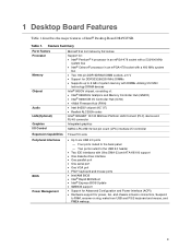
....intel.com/support/motherboards/desktop/ • Instructions on installing or upgrading the processor, see page 26 in Chapter 2 • The location of the two power connectors, see page 34 in damage to the Intel 845GV chipset and Intel processor. Table 3. The board has two ATX12V compliant power supply connectors that are not included with the desktop board and must be removed and replaced with supported higher speed processors. Desktop Board D845GVSR supports a single Intel Pentium 4 processor or Intel Celeron processor. Desktop Board D845GVSR supports the processors listed...
....intel.com/support/motherboards/desktop/ • Instructions on installing or upgrading the processor, see page 26 in Chapter 2 • The location of the two power connectors, see page 34 in damage to the Intel 845GV chipset and Intel processor. Table 3. The board has two ATX12V compliant power supply connectors that are not included with the desktop board and must be removed and replaced with supported higher speed processors. Desktop Board D845GVSR supports a single Intel Pentium 4 processor or Intel Celeron processor. Desktop Board D845GVSR supports the processors listed...
Product Guide
Page 14
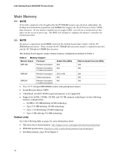
...; NOTE All memory components and DIMMs used with the desktop board must comply with the PC SDRAM specifications. If your memory modules do not support SPD, you will attempt to configure the memory controller for more information about: • The latest list of tested memory, http://support.intel.com/support/motherboards/desktop/ • SDRAM specifications, http://www.intel.com/technology/memory/pcsdram/spec/ • Installing memory, page 28 in Table 4. Memory Support Memory Speed Processor System Bus (MHz) Memory Speed Outcome (MHz...
...; NOTE All memory components and DIMMs used with the desktop board must comply with the PC SDRAM specifications. If your memory modules do not support SPD, you will attempt to configure the memory controller for more information about: • The latest list of tested memory, http://support.intel.com/support/motherboards/desktop/ • SDRAM specifications, http://www.intel.com/technology/memory/pcsdram/spec/ • Installing memory, page 28 in Table 4. Memory Support Memory Speed Processor System Bus (MHz) Memory Speed Outcome (MHz...
Product Guide
Page 16
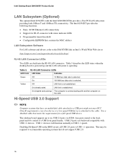
... device or a low-speed USB device is not established. Use a shielded cable that contains the MAC address LAN Subsystem Software For LAN software and drivers, refer to the cable. Disabling Hi-Speed USB in the BIOS reverts all USB 2.0 ports to a USB front panel header. Intel Desktop Board D845GVSR Product Guide LAN Subsystem (Optional) The optional Intel 82562ET (with status indicator LEDs • Programmable transit threshold • Configurable EEPROM that meets the requirements for RJ-45 connector with the Intel 82801DB ICH4) provides a Fast PCI LAN...
... device or a low-speed USB device is not established. Use a shielded cable that contains the MAC address LAN Subsystem Software For LAN software and drivers, refer to the cable. Disabling Hi-Speed USB in the BIOS reverts all USB 2.0 ports to a USB front panel header. Intel Desktop Board D845GVSR Product Guide LAN Subsystem (Optional) The optional Intel 82562ET (with status indicator LEDs • Programmable transit threshold • Configurable EEPROM that meets the requirements for RJ-45 connector with the Intel 82801DB ICH4) provides a Fast PCI LAN...
Product Guide
Page 17
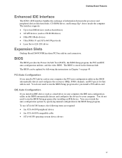
...) drives Expansion Slots Desktop Board D845GVSR has three PCI bus add-in card connectors. You do not need to run the BIOS Setup program after installing an IDE device. The BIOS can override the auto-configuration options by following items are required: • An ATA-66/100 peripheral device • An ATA-66/100 compatible cable • ATA-66/100 operating system device drivers 17 BIOS The BIOS provides the Power-On Self-Test (POST), the BIOS Setup program...
...) drives Expansion Slots Desktop Board D845GVSR has three PCI bus add-in card connectors. You do not need to run the BIOS Setup program after installing an IDE device. The BIOS can override the auto-configuration options by following items are required: • An ATA-66/100 peripheral device • An ATA-66/100 compatible cable • ATA-66/100 operating system device drivers 17 BIOS The BIOS provides the Power-On Self-Test (POST), the BIOS Setup program...

Product Guide
Page 18
... enter either the supervisor password or the user password to view and change all Setup options. PME# wakeup support ACPI ACPI gives the operating system direct control over the power management and Plug & Play functions of ACPI with the following restrictions: • The supervisor password gives unrestricted access to access Setup. Fan Connectors The desktop board has two chassis fan headers and one processor fan header. The password prompt is displayed before the computer is set for the Setup and for the location...
... enter either the supervisor password or the user password to view and change all Setup options. PME# wakeup support ACPI ACPI gives the operating system direct control over the power management and Plug & Play functions of ACPI with the following restrictions: • The supervisor password gives unrestricted access to access Setup. Fan Connectors The desktop board has two chassis fan headers and one processor fan header. The password prompt is displayed before the computer is set for the Setup and for the location...

Product Guide
Page 19
... a dual-colored power LED on the desktop board. The desktop board's standby power indicator, shown in Figure 2, is lit when there is indicated by a wake-up device or event, the system quickly returns to RAM (Instantly Available PC Technology) CAUTION For Instantly Available PC technology, the 5 V standby line for the location of the chassis intrusion header. Instantly Available PC technology enables the board to enter the ACPI S3 (Suspend-to support multiple wake...
... a dual-colored power LED on the desktop board. The desktop board's standby power indicator, shown in Figure 2, is lit when there is indicated by a wake-up device or event, the system quickly returns to RAM (Instantly Available PC Technology) CAUTION For Instantly Available PC technology, the 5 V standby line for the location of the chassis intrusion header. Instantly Available PC technology enables the board to enter the ACPI S3 (Suspend-to support multiple wake...

Product Guide
Page 32
... Out Front panel yellow LED On/Off Switch 5 Ground Ground 6 FPBUT_IN In Power switch 7 FP_RESET# In Reset switch Power 8 Ground Ground Not Connected 9 +5 V Power 10 N/C Not connected Installing a Front Panel Audio Solution Table 7 shows the pin assignments for the front panel header. Observe the precautions in "Before You Begin" on page 21. 2. Locate the front panel audio header (J8A1). 4. Remove the three jumpers from the header (this disables the back panel audio connectors). 5. Remove the cover. Intel Desktop Board D845GVSR Product Guide Connecting the Front...
... Out Front panel yellow LED On/Off Switch 5 Ground Ground 6 FPBUT_IN In Power switch 7 FP_RESET# In Reset switch Power 8 Ground Ground Not Connected 9 +5 V Power 10 N/C Not connected Installing a Front Panel Audio Solution Table 7 shows the pin assignments for the front panel header. Observe the precautions in "Before You Begin" on page 21. 2. Locate the front panel audio header (J8A1). 4. Remove the three jumpers from the header (this disables the back panel audio connectors). 5. Remove the cover. Intel Desktop Board D845GVSR Product Guide Connecting the Front...
Product Guide
Page 37
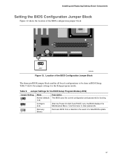
... the Setup program modes. Use this menu to be done in the event of the BIOS configuration jumper block. 31 J9H2 OM16282 Figure 12. Table 9. Location of the BIOS Configuration Jumper Block The three-pin BIOS jumper block enables all board configurations to clear passwords. 31 Recovery (None) Recovers BIOS from a diskette in BIOS Setup. Table 9 shows the jumper settings for booting. 31 Configure (2-3) After the Power-On Self-Test (POST) runs, the BIOS displays the Maintenance Menu. Installing and Replacing Desktop Board Components Setting the BIOS Configuration Jumper...
... the Setup program modes. Use this menu to be done in the event of the BIOS configuration jumper block. 31 J9H2 OM16282 Figure 12. Table 9. Location of the BIOS Configuration Jumper Block The three-pin BIOS jumper block enables all board configurations to clear passwords. 31 Recovery (None) Recovers BIOS from a diskette in BIOS Setup. Table 9 shows the jumper settings for booting. 31 Configure (2-3) After the Power-On Self-Test (POST) runs, the BIOS displays the Maintenance Menu. Installing and Replacing Desktop Board Components Setting the BIOS Configuration Jumper...
Product Guide
Page 38
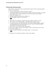
.... Replace the cover, plug in the computer and the configuration jumper block is installed in the computer, and turn on the computer, and allow it to save the current values and exit Setup. 10. To restore normal operation, place the jumper on pins 1-2 as shown below . 31 13. Setup displays the maintenance menu. 8. Remove the computer cover. 12. Turn off all peripheral devices connected to select Clear Passwords. Intel Desktop Board D845GVSR...
.... Replace the cover, plug in the computer and the configuration jumper block is installed in the computer, and turn on the computer, and allow it to save the current values and exit Setup. 10. To restore normal operation, place the jumper on pins 1-2 as shown below . 31 13. Setup displays the maintenance menu. 8. Remove the computer cover. 12. Turn off all peripheral devices connected to select Clear Passwords. Intel Desktop Board D845GVSR...
Product Guide
Page 45
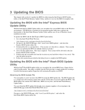
... your hard drive. (You can update the system BIOS from a floppy disk or other applications. Double-click the executable file from the Web provides a simple method for multiple identical systems.) 4. Updating the BIOS with the Intel® Express BIOS Update Utility With the Intel Express BIOS Update utility you are updating the BIOS for creating a bootable flash memory update floppy that will be rebooted at : http://support.intel.com/support/motherboards/desktop/ Navigate to the D845GVSR page, click "[view] Latest BIOS updates", and...
... your hard drive. (You can update the system BIOS from a floppy disk or other applications. Double-click the executable file from the Web provides a simple method for multiple identical systems.) 4. Updating the BIOS with the Intel® Express BIOS Update Utility With the Intel Express BIOS Update utility you are updating the BIOS for creating a bootable flash memory update floppy that will be rebooted at : http://support.intel.com/support/motherboards/desktop/ Navigate to the D845GVSR page, click "[view] Latest BIOS updates", and...
Product Guide
Page 49
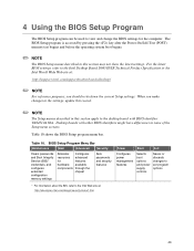
... 10 shows the BIOS Setup program menu bar. 4 Using the BIOS Setup Program The BIOS Setup program can be used to view and change the BIOS settings for features hardware available components through the chipset Sets passwords and security features Power Boot Exit Configures power management features Selects boot options and power supply controls Saves or discards changes to set program options * For information about the BIS, refer to the Intel Web site at : http://support.intel.com/support/motherboards/desktop/ ✏ NOTE...
... 10 shows the BIOS Setup program menu bar. 4 Using the BIOS Setup Program The BIOS Setup program can be used to view and change the BIOS settings for features hardware available components through the chipset Sets passwords and security features Power Boot Exit Configures power management features Selects boot options and power supply controls Saves or discards changes to set program options * For information about the BIS, refer to the Intel Web site at : http://support.intel.com/support/motherboards/desktop/ ✏ NOTE...
Product Guide
Page 52
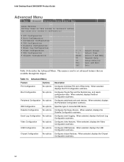
... When selected, displays the Chipset Configuration submenu. 52 When selected, displays the Peripheral Configuration submenu. When selected, displays the Boot Configuration submenu. Specifies type of connected IDE device. Configures video features. When selected, displays the USB Configuration submenu. Table 14. When selected, displays the Diskette Configuration submenu. Configures peripheral ports and devices. Intel Desktop Board D845GVSR Product Guide Advanced Menu Main Advanced Security Power Boot Exit Setup Warning: Setting items on this screen to incorrect...
... When selected, displays the Chipset Configuration submenu. 52 When selected, displays the Peripheral Configuration submenu. When selected, displays the Boot Configuration submenu. Specifies type of connected IDE device. Configures video features. When selected, displays the USB Configuration submenu. Table 14. When selected, displays the Diskette Configuration submenu. Configures peripheral ports and devices. Intel Desktop Board D845GVSR Product Guide Advanced Menu Main Advanced Security Power Boot Exit Setup Warning: Setting items on this screen to incorrect...
Product Guide
Page 57
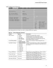
...connected IDE device. Disabled disables the integrated IDE controller. Reports type of connected IDE device. Reports type of connected IDE device. Using the BIOS Setup Program IDE Configuration Submenu Main Advanced Security IDE Configuration Power Boot Exit IDE Controller [Both] PCI IDE Bus Master Hard Disk Pre-Delay [Enabled] [Disabled] ` Primary IDE Master : ` Primary IDE Slave : ` Secondary IDE Master : ` Secondary IDE Master : [xxxxxxx] [Not Detected] [xxxxxxx] [Xxxxxxx] m o n p Enter F1 P9 F10 ESC Select Screen Select Item Select ` Sub-Menu General Help Setup Defaults...
...connected IDE device. Disabled disables the integrated IDE controller. Reports type of connected IDE device. Reports type of connected IDE device. Using the BIOS Setup Program IDE Configuration Submenu Main Advanced Security IDE Configuration Power Boot Exit IDE Controller [Both] PCI IDE Bus Master Hard Disk Pre-Delay [Enabled] [Disabled] ` Primary IDE Master : ` Primary IDE Slave : ` Secondary IDE Master : ` Secondary IDE Master : [xxxxxxx] [Not Detected] [xxxxxxx] [Xxxxxxx] m o n p Enter F1 P9 F10 ESC Select Screen Select Item Select ` Sub-Menu General Help Setup Defaults...
Product Guide
Page 58
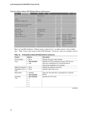
Intel Desktop Board D845GVSR Product Guide Primary/Secondary IDE Master/Slave Submenus Main Advanced Security Power Boot Exit ` [ : Xxxxxxxxx ] Type Maximum Capacity [Auto] [Auto] Configuration Options Selected By BIOS LBA Mode : Block Mode : PIO Mode : Ultra DMA : Cable Detected : [Supported] 16 Sectors Auto Disabled Serial m o n p Enter F1 P9 F10 ESC Select Screen Select Item Select ` Sub-Menu General Help Setup Defaults Save and Exit Exit There are four IDE submenus: Primary master, primary slave, secondary master, and secondary slave. Primary...
Intel Desktop Board D845GVSR Product Guide Primary/Secondary IDE Master/Slave Submenus Main Advanced Security Power Boot Exit ` [ : Xxxxxxxxx ] Type Maximum Capacity [Auto] [Auto] Configuration Options Selected By BIOS LBA Mode : Block Mode : PIO Mode : Ultra DMA : Cable Detected : [Supported] 16 Sectors Auto Disabled Serial m o n p Enter F1 P9 F10 ESC Select Screen Select Item Select ` Sub-Menu General Help Setup Defaults Save and Exit Exit There are four IDE submenus: Primary master, primary slave, secondary master, and secondary slave. Primary...
Product Guide
Page 66
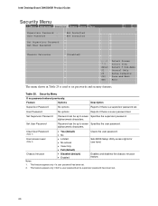
Intel Desktop Board D845GVSR Product Guide Security Menu Main Advanced Security Power Boot Exit Supervisor Password : User Password : Not Installed Not Installed Set Supervisor Password Set User Password Chassis Intrusion [Disabled] m o n p Enter F1 P9 F10 ESC Select Screen Select Item Select ` Sub-Menu General Help Setup Defaults Save and Exit Exit The menu shown in Table 25 is used to set . Security Menu If no password entered previously: Feature Options Description Supervisor Password No options Reports if there is a user password set . 2. alphanumeric characters. ...
Intel Desktop Board D845GVSR Product Guide Security Menu Main Advanced Security Power Boot Exit Supervisor Password : User Password : Not Installed Not Installed Set Supervisor Password Set User Password Chassis Intrusion [Disabled] m o n p Enter F1 P9 F10 ESC Select Screen Select Item Select ` Sub-Menu General Help Setup Defaults Save and Exit Exit The menu shown in Table 25 is used to set . Security Menu If no password entered previously: Feature Options Description Supervisor Password No options Reports if there is a user password set . 2. alphanumeric characters. ...
Product Guide
Page 69
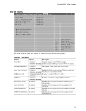
... available types of POST messages. Boot Menu Feature Options Description Silent Boot • Disabled Disabled displays normal POST messages. • Enabled (default) Enabled displays OEM logo instead of boot devices. Table 28. Using the BIOS Setup Program Boot Menu Main Advanced Security Power Boot Exit Silent BOOT Intel ® Rapid BIOS Boot Scan User Flash Area PXE Boot to LAN USB Boot [Enabled] [Enabled] [Enabled] [Disabled] [Enabled] ` Boot Device Priority ` Hard Disk Drives ` Removable Devices ` ATAPI CD-ROM Drives m o n p Enter F1 P9 F10 ESC Select Screen Select...
... available types of POST messages. Boot Menu Feature Options Description Silent Boot • Disabled Disabled displays normal POST messages. • Enabled (default) Enabled displays OEM logo instead of boot devices. Table 28. Using the BIOS Setup Program Boot Menu Main Advanced Security Power Boot Exit Silent BOOT Intel ® Rapid BIOS Boot Scan User Flash Area PXE Boot to LAN USB Boot [Enabled] [Enabled] [Enabled] [Disabled] [Enabled] ` Boot Device Priority ` Hard Disk Drives ` Removable Devices ` ATAPI CD-ROM Drives m o n p Enter F1 P9 F10 ESC Select Screen Select...
User Guide
Page 16
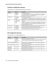
... IDE Slave submenu. 2-6 Using the BIOS Setup Program Output Only operates in PS/2-compatible mode. Both enables both IDE controllers. Auto assigns the first free COM port, normally COM1, the address 3F8h, and the interrupt IRQ4. Bi-directional operates in AT†-compatible mode. Enables or disables the onboard audio subsystem. Enables or disables the onboard LAN device. For boards with no onboard LAN subsystem, this option does not appear. Reports type of connected IDE device. Reports type of connected IDE device. Configures the parallel port. IDE Configuration...
... IDE Slave submenu. 2-6 Using the BIOS Setup Program Output Only operates in PS/2-compatible mode. Both enables both IDE controllers. Auto assigns the first free COM port, normally COM1, the address 3F8h, and the interrupt IRQ4. Bi-directional operates in AT†-compatible mode. Enables or disables the onboard audio subsystem. Enables or disables the onboard LAN device. For boards with no onboard LAN subsystem, this option does not appear. Reports type of connected IDE device. Reports type of connected IDE device. Configures the parallel port. IDE Configuration...

User Guide
Page 20
... from Network USB Boot Boot Device Priority Options • Disabled • Enabled • Disabled • Enabled No options Hard Disk Drives No options Removable Devices No options ATAPI CD-ROM Drives No options Description Disables or enables boot from the available removable devices. Specifies the boot sequence from Network. When selected, displays the Secondary IDE Slave submenu. Power Menu This menu is for setting the boot features and the boot sequence. Specifies the boot sequence from the available ATAPI CD-ROM drives. Feature ACPI Suspend State Wake on LAN...
... from Network USB Boot Boot Device Priority Options • Disabled • Enabled • Disabled • Enabled No options Hard Disk Drives No options Removable Devices No options ATAPI CD-ROM Drives No options Description Disables or enables boot from the available removable devices. Specifies the boot sequence from Network. When selected, displays the Secondary IDE Slave submenu. Power Menu This menu is for setting the boot features and the boot sequence. Specifies the boot sequence from the available ATAPI CD-ROM drives. Feature ACPI Suspend State Wake on LAN...


