
Product Specification
Page 2
... matter. Date July 2010 This product specification applies to only the standard Intel® Desktop Board D425KT and Intel® Desktop Board D425KTW with BIOS identifier MWPNT10N.86A Changes to specifications and product descriptions at any time, without notice. The furnishing of the Intel® Desktop Board D425KT and Intel® Desktop Board D425KTW Technical Product Specification.
... matter. Date July 2010 This product specification applies to only the standard Intel® Desktop Board D425KT and Intel® Desktop Board D425KTW with BIOS identifier MWPNT10N.86A Changes to specifications and product descriptions at any time, without notice. The furnishing of the Intel® Desktop Board D425KT and Intel® Desktop Board D425KTW Technical Product Specification.
Product Specification
Page 3
... The features supported by the BIOS Setup program A description of the BIOS error messages, beep codes, and POST codes Regulatory compliance and battery disposal information Typographical Conventions This section contains information about the Intel Desktop Board D425KT and Intel Desktop Board D425KTW and its ... help you avoid damaging hardware or losing data. Intended Audience The TPS is specifically not intended for the Intel® Desktop Board D425KT and Intel® Desktop Board D425KTW. It describes the standard product and available manufacturing options. Not all of these...
... The features supported by the BIOS Setup program A description of the BIOS error messages, beep codes, and POST codes Regulatory compliance and battery disposal information Typographical Conventions This section contains information about the Intel Desktop Board D425KT and Intel Desktop Board D425KTW and its ... help you avoid damaging hardware or losing data. Intended Audience The TPS is specifically not intended for the Intel® Desktop Board D425KT and Intel® Desktop Board D425KTW. It describes the standard product and available manufacturing options. Not all of these...
Product Specification
Page 5
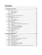
... 1.1.1 Feature Summary 9 1.1.2 Board Layout 11 1.1.3 Block Diagram 13 1.2 Online Support 14 1.3 Processor 14 1.3.1 Intel D425 Graphics Subsystem 15 1.4 System Memory 16 1.5 Intel® NM10 Express Chipset 17 1.5.2 USB 19 1.5.3 SATA Support 19 1.6 Real-Time Clock Subsystem 20 1.7 Legacy ...33 2.1.1 Addressable Memory 33 2.2 Connectors and Headers 36 2.2.1 Back Panel 37 2.2.2 Component-side Connectors and Headers 39 2.3 BIOS Configuration Jumper Block 49 2.4 Mechanical Considerations 51 2.4.1 Form Factor 51 2.5 Electrical Considerations 52 2.5.1 Fan Header Current Capability 52...
... 1.1.1 Feature Summary 9 1.1.2 Board Layout 11 1.1.3 Block Diagram 13 1.2 Online Support 14 1.3 Processor 14 1.3.1 Intel D425 Graphics Subsystem 15 1.4 System Memory 16 1.5 Intel® NM10 Express Chipset 17 1.5.2 USB 19 1.5.3 SATA Support 19 1.6 Real-Time Clock Subsystem 20 1.7 Legacy ...33 2.1.1 Addressable Memory 33 2.2 Connectors and Headers 36 2.2.1 Back Panel 37 2.2.2 Component-side Connectors and Headers 39 2.3 BIOS Configuration Jumper Block 49 2.4 Mechanical Considerations 51 2.4.1 Form Factor 51 2.5 Electrical Considerations 52 2.5.1 Fan Header Current Capability 52...
Product Specification
Page 6
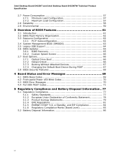
Intel Desktop Board D425KT and Intel Desktop Board D425KTW Technical Product Specification 2.7 Power Consumption 57 2.7.1 Minimum Load Configuration 57 2.7.2 Maximum Load Configuration 57 2.8 Reliability 58 2.9 Environmental 59 3 Overview of BIOS Features 61 3.1 Introduction 61 3.2 BIOS Flash Memory Organization 62 3.3 Resource Configuration 62 3.3.1 PCI* Autoconfiguration 62 3.4 System Management BIOS (SMBIOS 63 3.5 Legacy USB Support 64 3.6 BIOS Updates 65 3.6.1 BIOS Recovery...
Intel Desktop Board D425KT and Intel Desktop Board D425KTW Technical Product Specification 2.7 Power Consumption 57 2.7.1 Minimum Load Configuration 57 2.7.2 Maximum Load Configuration 57 2.8 Reliability 58 2.9 Environmental 59 3 Overview of BIOS Features 61 3.1 Introduction 61 3.2 BIOS Flash Memory Organization 62 3.3 Resource Configuration 62 3.3.1 PCI* Autoconfiguration 62 3.4 System Management BIOS (SMBIOS 63 3.5 Legacy USB Support 64 3.6 BIOS Updates 65 3.6.1 BIOS Recovery...

Product Specification
Page 7
...(D425KTW only 42 15. Front Panel Wireless Activity LED Header (D425KTW only 43 19. Front Panel USB Header with Intel Z-U130 USB Solid-State Drive or Compatible Device Support (D425KTW only 48 14. Major Board Components 11 2. LAN ...11. Power States and Targeted System Power 28 8. Component-side Connectors and Headers 39 11. Connection Diagram for Intel HD Audio 43 20. LVDS Panel Voltage Selection Jumper (D425KTW only 42 14. LVDS Data Connector - 30-... 2. Location of Pressing the Power Switch 27 7. Contents Figures 1. Location of the BIOS Configuration Jumper Block 49 15.
...(D425KTW only 42 15. Front Panel Wireless Activity LED Header (D425KTW only 43 19. Front Panel USB Header with Intel Z-U130 USB Solid-State Drive or Compatible Device Support (D425KTW only 48 14. Major Board Components 11 2. LAN ...11. Power States and Targeted System Power 28 8. Component-side Connectors and Headers 39 11. Connection Diagram for Intel HD Audio 43 20. LVDS Panel Voltage Selection Jumper (D425KTW only 42 14. LVDS Data Connector - 30-... 2. Location of Pressing the Power Switch 27 7. Contents Figures 1. Location of the BIOS Configuration Jumper Block 49 15.
Product Specification
Page 8
... LED 47 26. Minimum Load Configuration Current and Power Results 57 30. Intel Desktop Board D425KT and Intel Desktop Board D425KTW Environmental Specifications 59 32. BIOS Beep Codes 69 38. BIOS Error Messages 70 40. Safety Standards 77 44. Intel Desktop Board D425KT and Intel Desktop Board D425KTW Technical Product Specification 23. Fan Header Current Capability 52 28...
... LED 47 26. Minimum Load Configuration Current and Power Results 57 30. Intel Desktop Board D425KT and Intel Desktop Board D425KTW Environmental Specifications 59 32. BIOS Beep Codes 69 38. BIOS Error Messages 70 40. Safety Standards 77 44. Intel Desktop Board D425KT and Intel Desktop Board D425KTW Technical Product Specification 23. Fan Header Current Capability 52 28...
Product Specification
Page 10
Feature Summary (continued) BIOS • Intel® BIOS (resident in the SPI Flash device) • Support for Advanced Configuration and Power Interface (ACPI), Plug and Play, and SMBIOS Instantly Available • Support for ... detect out of range thermal values • One fan header • One fan sense input used to monitor fan activity • Fan speed control 10 Intel Desktop Board D425KT and Intel Desktop Board D425KTW Technical Product Specification Table 1.
Feature Summary (continued) BIOS • Intel® BIOS (resident in the SPI Flash device) • Support for Advanced Configuration and Power Interface (ACPI), Plug and Play, and SMBIOS Instantly Available • Support for ... detect out of range thermal values • One fan header • One fan sense input used to monitor fan activity • Fan speed control 10 Intel Desktop Board D425KT and Intel Desktop Board D425KTW Technical Product Specification Table 1.
Product Specification
Page 12
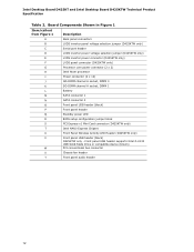
Intel Desktop Board D425KT and Intel Desktop Board D425KTW Technical Product Specification Table 2. Board Components Shown in Figure 1 Item/callout from Figure 1 Description A Back panel connectors B LVDS ...DIMM 1 L Battery M SATA connector 1 N SATA connector 0 O Front panel USB header (black) P Front panel header Q Standby power LED R BIOS setup configuration jumper block S PCI Express x1 Mini Card connector (D425KTW only) T Intel NM10 Express Chipset U Front Panel Wireless Activity LED Header (D425KTW only) V Front panel USB header (black) D425KTW only - Front...
Intel Desktop Board D425KT and Intel Desktop Board D425KTW Technical Product Specification Table 2. Board Components Shown in Figure 1 Item/callout from Figure 1 Description A Back panel connectors B LVDS ...DIMM 1 L Battery M SATA connector 1 N SATA connector 0 O Front panel USB header (black) P Front panel header Q Standby power LED R BIOS setup configuration jumper block S PCI Express x1 Mini Card connector (D425KTW only) T Intel NM10 Express Chipset U Front Panel Wireless Activity LED Header (D425KTW only) V Front panel USB header (black) D425KTW only - Front...
Product Specification
Page 14
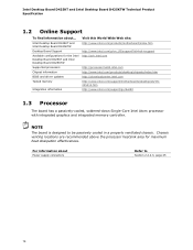
... about Power supply connectors Refer to be passively cooled in a properly ventilated chassis. Chassis venting locations are recommended above the processor heatsink area for the Intel Desktop Board D425KT and Intel Desktop Board D425KTW Supported processors Chipset information BIOS and driver updates Tested memory Integration information Visit this World Wide Web site: http://www...
... about Power supply connectors Refer to be passively cooled in a properly ventilated chassis. Chassis venting locations are recommended above the processor heatsink area for the Intel Desktop Board D425KT and Intel Desktop Board D425KTW Supported processors Chipset information BIOS and driver updates Tested memory Integration information Visit this World Wide Web site: http://www...
Product Specification
Page 16
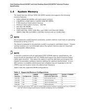
Intel Desktop Board D425KT and Intel Desktop Board D425KTW Technical Product Specification 1.4 System Memory The board has two 204-pin DDR3 SO-DIMM sockets and supports the following memory features: • ... memory will run at 800 MHz) NOTE Due to be impacted or the SODIMMs may be passively cooled in a properly ventilated chassis. This allows the BIOS to read the SPD data and program the chipset to single-sided memory modules (containing one row of 85 oC. The board is installed, performance...
Intel Desktop Board D425KT and Intel Desktop Board D425KTW Technical Product Specification 1.4 System Memory The board has two 204-pin DDR3 SO-DIMM sockets and supports the following memory features: • ... memory will run at 800 MHz) NOTE Due to be impacted or the SODIMMs may be passively cooled in a properly ventilated chassis. This allows the BIOS to read the SPD data and program the chipset to single-sided memory modules (containing one row of 85 oC. The board is installed, performance...
Product Specification
Page 18
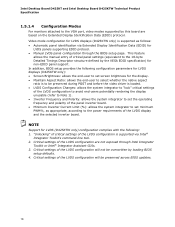
... preserved during POST and before the video driver is to be preserved across BIOS updates. 18 Intel Desktop Board D425KT and Intel Desktop Board D425KTW Technical Product Specification 1.5.1.4 Configuration Modes For monitors attached to the VGA port, video modes supported by loading BIOS setup defaults. 4. NOTE Support for non-EDID panel support. This feature allows...
... preserved during POST and before the video driver is to be preserved across BIOS updates. 18 Intel Desktop Board D425KT and Intel Desktop Board D425KTW Technical Product Specification 1.5.1.4 Configuration Modes For monitors attached to the VGA port, video modes supported by loading BIOS setup defaults. 4. NOTE Support for non-EDID panel support. This feature allows...
Product Specification
Page 20
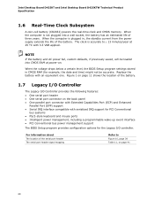
Intel Desktop Board D425KT and Intel Desktop Board D425KTW Technical Product Specification 1.6 Real-Time Clock ...Intelligent power management, including a programmable wake-up event interface • PCI Conventional bus power management support The BIOS Setup program provides configuration options for example, the date and time) might not be loaded into a wall .... 1.7 Legacy I/O Controller The Legacy I /O controller. When the voltage drops below a certain level, the BIOS Setup program settings stored in , the standby current from the power supply extends the life of three years. NOTE...
Intel Desktop Board D425KT and Intel Desktop Board D425KTW Technical Product Specification 1.6 Real-Time Clock ...Intelligent power management, including a programmable wake-up event interface • PCI Conventional bus power management support The BIOS Setup program provides configuration options for example, the date and time) might not be loaded into a wall .... 1.7 Legacy I/O Controller The Legacy I /O controller. When the voltage drops below a certain level, the BIOS Setup program settings stored in , the standby current from the power supply extends the life of three years. NOTE...
Product Specification
Page 29
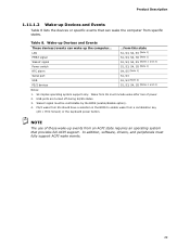
.../disable option). 4. Wake# signal must fully support ACPI wake events. 29 PS/2 wake from S5 should have a selection in the BIOS to enable wake from S5 must include wake after loss of these wake-up events from this state S1, S3, S4, S5 (Note 1) S1, S3, ...
.../disable option). 4. Wake# signal must fully support ACPI wake events. 29 PS/2 wake from S5 should have a selection in the BIOS to enable wake from S5 must include wake after loss of these wake-up events from this state S1, S3, S4, S5 (Note 1) S1, S3, ...
Product Specification
Page 31
While in the BIOS). 1.11.2.6 Wake from PS/2 Devices PS/2 keyboard activity wakes the computer from an ACPI S1, S3, S4, or S5 state. Table 8 on page 29 lists ...
While in the BIOS). 1.11.2.6 Wake from PS/2 Devices PS/2 keyboard activity wakes the computer from an ACPI S1, S3, S4, or S5 state. Table 8 on page 29 lists ...
Product Specification
Page 33
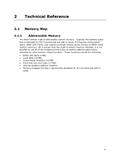
... Flash), and chipset overhead resides above the top of addressable system memory. These functions include the following: • BIOS/ SPI Flash (4 MB) • Local APIC (19 MB) • Direct Media Interface (40 MB) • Front side bus interrupts (17 MB) • Internal graphics address ...
... Flash), and chipset overhead resides above the top of addressable system memory. These functions include the following: • BIOS/ SPI Flash (4 MB) • Local APIC (19 MB) • Direct Media Interface (40 MB) • Front side bus interrupts (17 MB) • Internal graphics address ...
Product Specification
Page 34
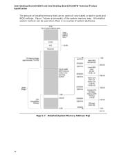
Intel Desktop Board D425KT and Intel Desktop Board D425KTW Technical Product Specification The amount of installed memory that can be used when there is no overlap of the system memory map. Figure 7. Figure 7 shows a schematic of system addresses. Detailed System Memory Address Map 34 All installed system memory can be used will vary based on add-in cards and BIOS settings.
Intel Desktop Board D425KT and Intel Desktop Board D425KTW Technical Product Specification The amount of installed memory that can be used when there is no overlap of the system memory map. Figure 7. Figure 7 shows a schematic of system addresses. Detailed System Memory Address Map 34 All installed system memory can be used will vary based on add-in cards and BIOS settings.

Product Specification
Page 35
... KB 64 KB 96 KB 160 KB 1 KB 127 KB 512 KB Description Extended memory Runtime BIOS Reserved Potential available high DOS memory (open to the PCI bus). Table 9. EFFFF C8000 - Video memory and BIOS Extended BIOS data (movable by memory manager software) Extended conventional memory Conventional memory 35 DFFFF 640 K - 800 K 639...
... KB 64 KB 96 KB 160 KB 1 KB 127 KB 512 KB Description Extended memory Runtime BIOS Reserved Potential available high DOS memory (open to the PCI bus). Table 9. EFFFF C8000 - Video memory and BIOS Extended BIOS data (movable by memory manager software) Extended conventional memory Conventional memory 35 DFFFF 640 K - 800 K 639...
Product Specification
Page 47
...) Blinking Sleeping (S3) Steady Green Running/Away (S0/S1) NOTE The LED states listed in Table 25 are default settings that can be modified through BIOS setup. States for a single-color LED. or dual-color LED. Systems built with a dual-color front panel power LED can also use alternate color state...
...) Blinking Sleeping (S3) Steady Green Running/Away (S0/S1) NOTE The LED states listed in Table 25 are default settings that can be modified through BIOS setup. States for a single-color LED. or dual-color LED. Systems built with a dual-color front panel power LED can also use alternate color state...
Product Specification
Page 49
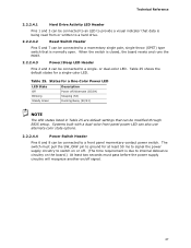
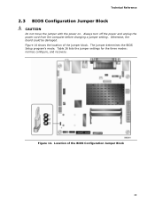
The jumper determines the BIOS Setup program's mode. Table 26 lists the jumper settings for the three modes: normal, configure, and recovery. Location of the jumper block. Always turn off the power and unplug the power cord from the computer before changing a jumper setting. Otherwise, the board could be damaged. Figure 14 shows the location of the BIOS Configuration Jumper Block 49 Technical Reference 2.3 BIOS Configuration Jumper Block CAUTION Do not move the jumper with the power on. Figure 14.
The jumper determines the BIOS Setup program's mode. Table 26 lists the jumper settings for the three modes: normal, configure, and recovery. Location of the jumper block. Always turn off the power and unplug the power cord from the computer before changing a jumper setting. Otherwise, the board could be damaged. Figure 14 shows the location of the BIOS Configuration Jumper Block 49 Technical Reference 2.3 BIOS Configuration Jumper Block CAUTION Do not move the jumper with the power on. Figure 14.
Product Specification
Page 50
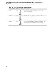
The BIOS attempts to recover the BIOS configuration. BIOS Configuration Jumper Settings Function/Mode Jumper Setting Configuration Normal 1-2 The BIOS uses current configuration information and passwords for more information on BIOS recovery. 50 The maintenance menu is displayed. Configure 2-3 Recovery None After the POST runs, Setup runs automatically. See Section 3.6.1 for booting. Intel Desktop Board D425KT and Intel Desktop Board D425KTW Technical Product Specification Table 26.
The BIOS attempts to recover the BIOS configuration. BIOS Configuration Jumper Settings Function/Mode Jumper Setting Configuration Normal 1-2 The BIOS uses current configuration information and passwords for more information on BIOS recovery. 50 The maintenance menu is displayed. Configure 2-3 Recovery None After the POST runs, Setup runs automatically. See Section 3.6.1 for booting. Intel Desktop Board D425KT and Intel Desktop Board D425KTW Technical Product Specification Table 26.


