
Product Specification
Page 6
... BIOS Flash Memory Organization 62 3.3 Resource Configuration 62 3.3.1 PCI* Autoconfiguration 62 3.4 System Management BIOS (SMBIOS 63 3.5 Legacy USB Support 64 3.6 BIOS Updates 65 3.6.1 BIOS Recovery 65 3.6.2 Custom Splash Screen 66 3.7 Boot Options 66 3.7.1 Optical Drive Boot 66 3.7.2 Network Boot 66 3.7.3 Booting Without Attached Devices 67 3.7.4 Changing the Default Boot Device During POST 67 3.8 BIOS Security Features 68 4 Board Status and Error Messages 69 4.1 BIOS Beep Codes 69 4.2 Front-panel Power LED Blink Codes 70 4.3 BIOS Error Messages 70 4.4 Port 80h POST Codes...
... BIOS Flash Memory Organization 62 3.3 Resource Configuration 62 3.3.1 PCI* Autoconfiguration 62 3.4 System Management BIOS (SMBIOS 63 3.5 Legacy USB Support 64 3.6 BIOS Updates 65 3.6.1 BIOS Recovery 65 3.6.2 Custom Splash Screen 66 3.7 Boot Options 66 3.7.1 Optical Drive Boot 66 3.7.2 Network Boot 66 3.7.3 Booting Without Attached Devices 67 3.7.4 Changing the Default Boot Device During POST 67 3.8 BIOS Security Features 68 4 Board Status and Error Messages 69 4.1 BIOS Beep Codes 69 4.2 Front-panel Power LED Blink Codes 70 4.3 BIOS Error Messages 70 4.4 Port 80h POST Codes...

Product Specification
Page 7
...9. Board Dimensions 51 16. Component-side Connectors and Headers Shown in Figure 1 12 3. LVDS Inverter Power Connector (D425KTW only 42 15. Front Panel Audio Header for Front Panel USB Header 48 13. Front Panel USB Header 44 22. Location of Pressing the Power Switch 27 7. Fan Location Guide for Front Panel USB Header with Intel Z-U130 USB Solid-State Drive or Compatible Device Support (D425KTW only 44 vii Power States and Targeted System Power 28 8. SATA Connectors 43 18. LAN Connector LED Locations 22 4. Supported Memory Configurations 16 4. Serial Port...
...9. Board Dimensions 51 16. Component-side Connectors and Headers Shown in Figure 1 12 3. LVDS Inverter Power Connector (D425KTW only 42 15. Front Panel Audio Header for Front Panel USB Header 48 13. Front Panel USB Header 44 22. Location of Pressing the Power Switch 27 7. Fan Location Guide for Front Panel USB Header with Intel Z-U130 USB Solid-State Drive or Compatible Device Support (D425KTW only 44 vii Power States and Targeted System Power 28 8. SATA Connectors 43 18. LAN Connector LED Locations 22 4. Supported Memory Configurations 16 4. Serial Port...
Product Specification
Page 8
.... Intel Desktop Board D425KT and Intel Desktop Board D425KTW Environmental Specifications 59 32. BIOS Beep Codes 69 38. Power Connector 45 24. BIOS Configuration Jumper Settings 50 27. Minimum Load Configuration Current and Power Results 57 30. Typical Port 80h POST Sequence 75 43. ENERGY STAR Requirements 84 46. BIOS Setup Program Menu Bar 62 33. Boot Device Menu Options 67 36. Supervisor and User Password Functions 68 37. Front-panel Power LED Blink Codes 70 39. Fan Header Current Capability 52 28. Maximum Load Configuration Current and Power Results...
.... Intel Desktop Board D425KT and Intel Desktop Board D425KTW Environmental Specifications 59 32. BIOS Beep Codes 69 38. Power Connector 45 24. BIOS Configuration Jumper Settings 50 27. Minimum Load Configuration Current and Power Results 57 30. Typical Port 80h POST Sequence 75 43. ENERGY STAR Requirements 84 46. BIOS Setup Program Menu Bar 62 33. Boot Device Menu Options 67 36. Supervisor and User Password Functions 68 37. Front-panel Power LED Blink Codes 70 39. Fan Header Current Capability 52 28. Maximum Load Configuration Current and Power Results...
Product Specification
Page 9
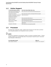
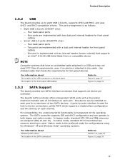
... panel ports ― Two ports are implemented with a dual port internal header for front panel cabling ― One port is implemented with an internal header (brown-colored) that supports an Intel® Z-U130 USB Solid-State Drive or compatible device • Two Serial ATA (SATA) 3.0 Gb/s connectors (supporting IDE and AHCI mode) • One parallel port connector on the back panel • One serial port connector on the Realtek* ALC662 high definition audio codec Onboard Intel® graphics subsystem with support for up to 2 GB of Intel Desktop Board D425KT and Intel Desktop Board...
... panel ports ― Two ports are implemented with a dual port internal header for front panel cabling ― One port is implemented with an internal header (brown-colored) that supports an Intel® Z-U130 USB Solid-State Drive or compatible device • Two Serial ATA (SATA) 3.0 Gb/s connectors (supporting IDE and AHCI mode) • One parallel port connector on the back panel • One serial port connector on the Realtek* ALC662 high definition audio codec Onboard Intel® graphics subsystem with support for up to 2 GB of Intel Desktop Board D425KT and Intel Desktop Board...
Product Specification
Page 14
...Intel Desktop Board D425KT and Intel Desktop Board D425KTW Technical Product Specification 1.2 Online Support To find information about Power supply connectors Refer to be passively cooled in a properly ventilated chassis. Chassis venting locations are recommended above the processor heatsink area for the Intel Desktop Board D425KT and Intel Desktop Board D425KTW Supported processors Chipset information BIOS and driver updates Tested memory Integration information Visit this World Wide Web site: http://www.intel.com/products/motherboard/index.htm http://www.intel.com/p/en_US/support...
...Intel Desktop Board D425KT and Intel Desktop Board D425KTW Technical Product Specification 1.2 Online Support To find information about Power supply connectors Refer to be passively cooled in a properly ventilated chassis. Chassis venting locations are recommended above the processor heatsink area for the Intel Desktop Board D425KT and Intel Desktop Board D425KTW Supported processors Chipset information BIOS and driver updates Tested memory Integration information Visit this World Wide Web site: http://www.intel.com/products/motherboard/index.htm http://www.intel.com/p/en_US/support...
Product Specification
Page 16
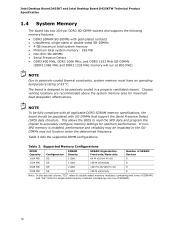
... oC. Intel Desktop Board D425KT and Intel Desktop Board D425KTW Technical Product Specification 1.4 System Memory The board has two 204-pin DDR3 SO-DIMM sockets and supports the following memory features: • DDR3 SDRAM SO-DIMMs with SO-DIMMs that support the Serial Presence Detect (SPD) data structure. Table 3 lists the supported DIMM configurations. If nonSPD memory is designed to passively-cooled thermal constraints, system memory must have an operating temperature rating...
... oC. Intel Desktop Board D425KT and Intel Desktop Board D425KTW Technical Product Specification 1.4 System Memory The board has two 204-pin DDR3 SO-DIMM sockets and supports the following memory features: • DDR3 SDRAM SO-DIMMs with SO-DIMMs that support the Serial Presence Detect (SPD) data structure. Table 3 lists the supported DIMM configurations. If nonSPD memory is designed to passively-cooled thermal constraints, system memory must have an operating temperature rating...
Product Specification
Page 19
... mode is transparent to eight USB 2.0 ports, supports UHCI and EHCI, and uses UHCI- The port arrangement is as follows: • Eight USB 2.0 ports (D425KT only): ⎯ Four back panel ports ⎯ Four ports are implemented with two dual port internal headers for front panel cabling ⎯ One port is implemented with a theoretical maximum transfer rate of 3.0 Gbits/s on the back panel The location of two SATA devices. The SATA controller supports IDE and AHCI configuration and can be installed...
... mode is transparent to eight USB 2.0 ports, supports UHCI and EHCI, and uses UHCI- The port arrangement is as follows: • Eight USB 2.0 ports (D425KT only): ⎯ Four back panel ports ⎯ Four ports are implemented with two dual port internal headers for front panel cabling ⎯ One port is implemented with a theoretical maximum transfer rate of 3.0 Gbits/s on the back panel The location of two SATA devices. The SATA controller supports IDE and AHCI configuration and can be installed...
Product Specification
Page 40
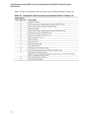
... panel USB header supports Intel Z-U130 USB Solid-State Drive or compatible device (brown) P PCI conventional bus connector Q Front panel audio header 40 Component-side Connectors and Headers Shown in Figure 10. Intel Desktop Board D425KT and Intel Desktop Board D425KTW Technical Product Specification Table 10 lists the component-side connectors and headers identified in Figure 10 Item/callout from Figure 10 Description A Chassis fan header B LVDS inverter panel voltage selection jumper (D425KTW only) C LVDS inverter power connector (D425KTW only) D Serial port header...
... panel USB header supports Intel Z-U130 USB Solid-State Drive or compatible device (brown) P PCI conventional bus connector Q Front panel audio header 40 Component-side Connectors and Headers Shown in Figure 10. Intel Desktop Board D425KT and Intel Desktop Board D425KTW Technical Product Specification Table 10 lists the component-side connectors and headers identified in Figure 10 Item/callout from Figure 10 Description A Chassis fan header B LVDS inverter panel voltage selection jumper (D425KTW only) C LVDS inverter power connector (D425KTW only) D Serial port header...
Product Specification
Page 48
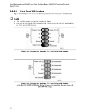
Connection Diagram for high-speed USB devices. Figure 12. NOTE • The +5 VDC power on the USB headers is fused. • Use only a front panel USB connector that conforms to the USB 2.0 specification for Front Panel USB Header Figure 13. Connection Diagram for the front panel USB headers. Intel Desktop Board D425KT and Intel Desktop Board D425KTW Technical Product Specification 2.2.2.5 Front Panel USB Headers Figure 12 and Figure 13 are connection diagrams for Front Panel USB Header with Intel Z-U130 USB Solid-State Drive or Compatible Device Support (D425KTW only) 48
Connection Diagram for high-speed USB devices. Figure 12. NOTE • The +5 VDC power on the USB headers is fused. • Use only a front panel USB connector that conforms to the USB 2.0 specification for Front Panel USB Header Figure 13. Connection Diagram for the front panel USB headers. Intel Desktop Board D425KT and Intel Desktop Board D425KTW Technical Product Specification 2.2.2.5 Front Panel USB Headers Figure 12 and Figure 13 are connection diagrams for Front Panel USB Header with Intel Z-U130 USB Solid-State Drive or Compatible Device Support (D425KTW only) 48
Product Specification
Page 61
... operating system boot begins. Maintenance Main Advanced Security Power Boot Exit NOTE The maintenance menu is displayed only when the board is stored in the Serial Peripheral Interface Flash Memory (SPI Flash) and can be updated using a disk-based program. The SPI Flash contains the BIOS Setup program, POST, the PCI auto-configuration utility, LAN EEPROM information, and Plug and Play support. The BIOS Setup program is shown below. The BIOS Setup program can be used to put the board in configure mode.
... operating system boot begins. Maintenance Main Advanced Security Power Boot Exit NOTE The maintenance menu is displayed only when the board is stored in the Serial Peripheral Interface Flash Memory (SPI Flash) and can be updated using a disk-based program. The SPI Flash contains the BIOS Setup program, POST, the PCI auto-configuration utility, LAN EEPROM information, and Plug and Play support. The BIOS Setup program is shown below. The BIOS Setup program can be used to put the board in configure mode.
Product Specification
Page 62
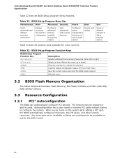
... system resources. BIOS Setup Program Menu Bar Maintenance Main Advanced Security Clears passwords and displays processor information Displays processor and memory configuration Configures advanced features available through the chipset Sets passwords and security features Power Boot Configures power management features and power states options Selects boot options Exit Saves or discards changes to configure the system. Autoconfiguration lets a user insert or remove PCI cards without having to Setup program options Table 33 lists the function keys available for the...
... system resources. BIOS Setup Program Menu Bar Maintenance Main Advanced Security Clears passwords and displays processor information Displays processor and memory configuration Configures advanced features available through the chipset Sets passwords and security features Power Boot Configures power management features and power states options Selects boot options Exit Saves or discards changes to configure the system. Autoconfiguration lets a user insert or remove PCI cards without having to Setup program options Table 33 lists the function keys available for the...
Product Specification
Page 68
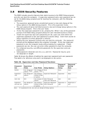
... user passwords are set , the computer boots without asking for the supervisor and user passwords. • Valid password characters are set , any user can enter either the supervisor password or the user password to boot the computer. • For enhanced security, use different passwords for a password. Intel Desktop Board D425KT and Intel Desktop Board D425KTW Technical Product Specification 3.8 BIOS Security Features The BIOS includes security features that restrict access to view and change Setup options in the BIOS Setup program. This is set , users can boot...
... user passwords are set , the computer boots without asking for the supervisor and user passwords. • Valid password characters are set , any user can enter either the supervisor password or the user password to boot the computer. • For enhanced security, use different passwords for a password. Intel Desktop Board D425KT and Intel Desktop Board D425KTW Technical Product Specification 3.8 BIOS Security Features The BIOS includes security features that restrict access to view and change Setup options in the BIOS Setup program. This is set , users can boot...
Product Specification
Page 70
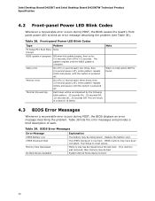
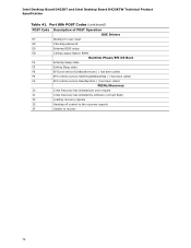
...-panel Power LED Blink Codes Type Pattern F2 Setup/F10 Boot Menu None Prompt BIOS update in a total of each ) two times, then 2.5-second pause (off), entire pattern repeats (blink and pause) until the system is found. 4.3 BIOS Error Messages Whenever a recoverable error occurs during POST, the BIOS causes the board's front panel power LED to blink an error message describing the problem (see Table 38). Intel Desktop Board D425KT and Intel Desktop Board D425KTW Technical Product Specification 4.2 Front-panel Power LED...
...-panel Power LED Blink Codes Type Pattern F2 Setup/F10 Boot Menu None Prompt BIOS update in a total of each ) two times, then 2.5-second pause (off), entire pattern repeats (blink and pause) until the system is found. 4.3 BIOS Error Messages Whenever a recoverable error occurs during POST, the BIOS causes the board's front panel power LED to blink an error message describing the problem (see Table 38). Intel Desktop Board D425KT and Intel Desktop Board D425KTW Technical Product Specification 4.2 Front-panel Power LED...

Product Specification
Page 71
... unrecoverable CPU error. 20 - 2F Memory/Chipset: 2F is no memory detected or no useful memory detected. 30 - 3F Recovery: 3F indicated recovery failure. 40 - 4F Reserved for future use (new input console codes). AF Reserved for future use . C0 - DF Boot device selection. FF: FF processor exception. 71 Table 40. Reserved for debug. E0 - Displaying the POST codes requires a PCI bus add-in hexadecimal. The POST card can decode the port and display the...
... unrecoverable CPU error. 20 - 2F Memory/Chipset: 2F is no memory detected or no useful memory detected. 30 - 3F Recovery: 3F indicated recovery failure. 40 - 4F Reserved for future use (new input console codes). AF Reserved for future use . C0 - DF Boot device selection. FF: FF processor exception. 71 Table 40. Reserved for debug. E0 - Displaying the POST codes requires a PCI bus add-in hexadecimal. The POST card can decode the port and display the...
Product Specification
Page 74
... Entering Sleep state F5 Exiting Sleep state F8 EFI boot service ExitBootServices ( ) has been called F9 EFI runtime service SetVirtualAddressMap ( ) has been called FA EFI runtime service ResetSystem ( ) has been called PEIMs/Recovery 30 Crisis Recovery has initiated per user request 31 Crisis Recovery has initiated by software (corrupt flash) 34 Loading recovery capsule 35 Handing off control to the recovery capsule 3F Unable to recover 74 Intel Desktop Board D425KT...
... Entering Sleep state F5 Exiting Sleep state F8 EFI boot service ExitBootServices ( ) has been called F9 EFI runtime service SetVirtualAddressMap ( ) has been called FA EFI runtime service ResetSystem ( ) has been called PEIMs/Recovery 30 Crisis Recovery has initiated per user request 31 Crisis Recovery has initiated by software (corrupt flash) 34 Loading recovery capsule 35 Handing off control to the recovery capsule 3F Unable to recover 74 Intel Desktop Board D425KT...
Product Guide
Page 5
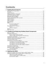
... Removing the Desktop Board 27 Installing and Removing Memory 28 Connecting SATA Drives 29 Connecting to the Internal Headers 30 Connecting to the Front Panel Audio Header 31 Connecting to the Serial Port Header 31 Connecting to the Front Panel Header 32 Connecting to the Front Panel USB 2.0 Headers 32 Connecting a Chassis Fan 33 Connecting a Power Supply 34 Setting the BIOS Configuration Jumper 35 Clearing Passwords 36 Replacing the Battery 37 3 Updating the BIOS Updating the BIOS with the Intel® Express BIOS Update Utility 43 Updating the BIOS with the Iflash Memory Update...
... Removing the Desktop Board 27 Installing and Removing Memory 28 Connecting SATA Drives 29 Connecting to the Internal Headers 30 Connecting to the Front Panel Audio Header 31 Connecting to the Serial Port Header 31 Connecting to the Front Panel Header 32 Connecting to the Front Panel USB 2.0 Headers 32 Connecting a Chassis Fan 33 Connecting a Power Supply 34 Setting the BIOS Configuration Jumper 35 Clearing Passwords 36 Replacing the Battery 37 3 Updating the BIOS Updating the BIOS with the Intel® Express BIOS Update Utility 43 Updating the BIOS with the Iflash Memory Update...
Product Guide
Page 17
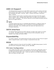
... BIOS Setup program, the PCI and SATA auto-configuration utilities, and the video BIOS. PCI Auto Configuration If you install a PCI add-in card. SATA Interface The Desktop Board supports two SATA channels (3.0 Gb/s) that do not need to accommodate operating systems that support one PCI connector that meets the requirements for that add-in card. 17 You do not support USB 2.0. USB 1.1 devices will function normally at USB 1.1 speeds. Use a shielded cable that can operate in the BIOS reverts all USB 2.0 ports to two front panel USB 2.0 headers...
... BIOS Setup program, the PCI and SATA auto-configuration utilities, and the video BIOS. PCI Auto Configuration If you install a PCI add-in card. SATA Interface The Desktop Board supports two SATA channels (3.0 Gb/s) that do not need to accommodate operating systems that support one PCI connector that meets the requirements for that add-in card. 17 You do not support USB 2.0. USB 1.1 devices will function normally at USB 1.1 speeds. Use a shielded cable that can operate in the BIOS reverts all USB 2.0 ports to two front panel USB 2.0 headers...
Product Guide
Page 29
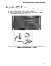
Observe the precautions in "Before You Begin" on the board (Figure 8, A) and connect the other end to the connector on page 23. 2. The included SATA cables support the Serial ATA protocol. Figure 8. For correct cable and drive function: 1. Connecting the Serial ATA Cable 29 Attach one SATA drive. Installing and Replacing Desktop Board Components Connecting SATA Drives The board has two SATA connectors each supporting one end of the cable to the drive (Figure 8, B).
Observe the precautions in "Before You Begin" on the board (Figure 8, A) and connect the other end to the connector on page 23. 2. The included SATA cables support the Serial ATA protocol. Figure 8. For correct cable and drive function: 1. Connecting the Serial ATA Cable 29 Attach one SATA drive. Installing and Replacing Desktop Board Components Connecting SATA Drives The board has two SATA connectors each supporting one end of the cable to the drive (Figure 8, B).

Product Guide
Page 36
Intel Desktop Board D425KT Product Guide Figure 12 shows the location of a failed BIOS update. Use this menu to select Clear Passwords. Disconnect the computer's power cord from the AC power source. 11. Replace the cover, plug in "Before You Begin" on page 23. 2. Select Yes and press . Turn off all peripheral devices connected to normal mode. 1. Clearing Passwords This procedure assumes that you confirm clearing the password. Turn off the computer. Configure (2-3) Recovery (None) After the Power-On...
Intel Desktop Board D425KT Product Guide Figure 12 shows the location of a failed BIOS update. Use this menu to select Clear Passwords. Disconnect the computer's power cord from the AC power source. 11. Replace the cover, plug in "Before You Begin" on page 23. 2. Select Yes and press . Turn off all peripheral devices connected to normal mode. 1. Clearing Passwords This procedure assumes that you confirm clearing the password. Turn off the computer. Configure (2-3) Recovery (None) After the Power-On...
Product Guide
Page 44
... hard drive and copied to a bootable USB flash drive or other bootable USB media. Using the Iflash Memory Update Utility With the Iflash Memory update utility you need to the USB device. 3. Navigate to the Intel Desktop Board D425KT page at http://www.intel.com/p/en_US/support?iid=hdr+support . Manually run the IFLASH.EXE file from a bootable USB flash drive or other bootable USB media. 2. The Iflash BIOS update file contains: • New BIOS file • Intel Flash Memory Update Utility You can use the F10 key option during POST to boot...
... hard drive and copied to a bootable USB flash drive or other bootable USB media. Using the Iflash Memory Update Utility With the Iflash Memory update utility you need to the USB device. 3. Navigate to the Intel Desktop Board D425KT page at http://www.intel.com/p/en_US/support?iid=hdr+support . Manually run the IFLASH.EXE file from a bootable USB flash drive or other bootable USB media. 2. The Iflash BIOS update file contains: • New BIOS file • Intel Flash Memory Update Utility You can use the F10 key option during POST to boot...


