Data Sheet
Page 2
... Trusted Computing Group and specific software for Directed I/O (Intel® VT-d)), a Intel TXT-enabled processor, chipset, BIOS, Authenticated Code Modules and an Intel TXT-compatible measured launched environment (MLE). Functionality, performance or other benefits will vary depending on hardware, software and overall system configuration. Enabling Execute Disable Bit functionality requires a PC with a processor with a processor, chipset, BIOS, operating system, device drivers and applications enabled...
... Trusted Computing Group and specific software for Directed I/O (Intel® VT-d)), a Intel TXT-enabled processor, chipset, BIOS, Authenticated Code Modules and an Intel TXT-compatible measured launched environment (MLE). Functionality, performance or other benefits will vary depending on hardware, software and overall system configuration. Enabling Execute Disable Bit functionality requires a PC with a processor with a processor, chipset, BIOS, operating system, device drivers and applications enabled...
Data Sheet
Page 3
...* Ports and Bifurcation 28 2.2.3.1 PCI Express* Bifurcated Mode 28 2.3 Direct Media Interface (DMI 28 2.3.1 DMI Error Flow 28 2.3.2 Processor/PCH Compatibility Assumptions 28 2.3.3 DMI Link Down 28 2.4 Platform Environment Control Interface (PECI 29 2.5 Interface Clocking 29 2.5.1 Internal Clocking Requirements 29 3 Technologies ...31 3.1 Intel® Virtualization Technology 31 3.1.1 Intel® VT-x Objectives 31 3.1.2 Intel® VT-x Features 31 Datasheet, Volume 1 3
...* Ports and Bifurcation 28 2.2.3.1 PCI Express* Bifurcated Mode 28 2.3 Direct Media Interface (DMI 28 2.3.1 DMI Error Flow 28 2.3.2 Processor/PCH Compatibility Assumptions 28 2.3.3 DMI Link Down 28 2.4 Platform Environment Control Interface (PECI 29 2.5 Interface Clocking 29 2.5.1 Internal Clocking Requirements 29 3 Technologies ...31 3.1 Intel® Virtualization Technology 31 3.1.1 Intel® VT-x Objectives 31 3.1.2 Intel® VT-x Features 31 Datasheet, Volume 1 3

Data Sheet
Page 5
... 7.9 DC Specifications 70 7.9.1 Voltage and Current Specifications 70 7.10 Platform Environmental Control Interface (PECI) DC Specifications 77 7.10.1 DC Characteristics 77 7.10.2 Input Device Hysteresis 78 8 Processor Land and Signal Information 79 8.1 Processor Land Assignments 79 Figures 1-1 Intel® Xeon® Processor 3400 Series Platform Diagram 10 2-1 Intel® Flex Memory Technology Operation 22 2-2 Dual-Channel Symmetric (Interleaved) and Dual-Channel Asymmetric...
... 7.9 DC Specifications 70 7.9.1 Voltage and Current Specifications 70 7.10 Platform Environmental Control Interface (PECI) DC Specifications 77 7.10.1 DC Characteristics 77 7.10.2 Input Device Hysteresis 78 8 Processor Land and Signal Information 79 8.1 Processor Land Assignments 79 Figures 1-1 Intel® Xeon® Processor 3400 Series Platform Diagram 10 2-1 Intel® Flex Memory Technology Operation 22 2-2 Dual-Channel Symmetric (Interleaved) and Dual-Channel Asymmetric...
Data Sheet
Page 9
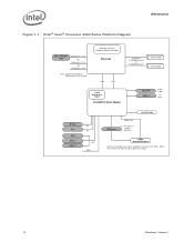
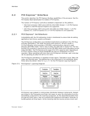
... specific features supported on individual Intel Xeon processor 3400 series SKUs, refer to the Intel® Xeon® X3480, X3470, X3460, X3450, X3440, X3430, and L3426 processors. Figure 1-1 shows an example server platform block diagram. Included in this document, the Intel® 3400 Series Chipset Platform Controller Hub may be referred to as "processor". Datasheet, Volume 1 9 Throughout this document, the Intel® Xeon® processor...
... specific features supported on individual Intel Xeon processor 3400 series SKUs, refer to the Intel® Xeon® X3480, X3470, X3460, X3450, X3440, X3430, and L3426 processors. Figure 1-1 shows an example server platform block diagram. Included in this document, the Intel® 3400 Series Chipset Platform Controller Hub may be referred to as "processor". Datasheet, Volume 1 9 Throughout this document, the Intel® Xeon® processor...
Data Sheet
Page 10
Refer to the Processor Specification Update for details. 10 Datasheet, Volume 1 Introduction Figure 1-1. Quad Core CPU w it h Int egrat ed Memory Cont roller Processor DMI PECI Int el® Management Engine Intel®3 400 Series Chipset 2 Channels (2 UDIMM/ Channel) Or (3 RDIMM/ Channel) DDR3 DIMMs DDR3 DIMMs ... Express* 8 x1 PCI Express* 2.0 Port s (2.5 GT/ s) Intel®HD Audio Gigabit Network Connection Som e technologies m ay not be enabled on all processor SKUs. Intel® Xeon® Processor 3400 Series Platform Diagram Discrete Graphics (PEG) PCI Express* 1x16 OR ...
Refer to the Processor Specification Update for details. 10 Datasheet, Volume 1 Introduction Figure 1-1. Quad Core CPU w it h Int egrat ed Memory Cont roller Processor DMI PECI Int el® Management Engine Intel®3 400 Series Chipset 2 Channels (2 UDIMM/ Channel) Or (3 RDIMM/ Channel) DDR3 DIMMs DDR3 DIMMs ... Express* 8 x1 PCI Express* 2.0 Port s (2.5 GT/ s) Intel®HD Audio Gigabit Network Connection Som e technologies m ay not be enabled on all processor SKUs. Intel® Xeon® Processor 3400 Series Platform Diagram Discrete Graphics (PEG) PCI Express* 1x16 OR ...

Data Sheet
Page 11
...-KB shared instruction/data second-level cache (L2) for each core • 8-MB shared instruction/data last-level cache (L3), shared among all processor SKUs. Intel® Xeon® Processor 3400 Series Supported Memory Summary Platform Memory Type # of non-ECC and ECC DIMMs is not supported. Mixing of Channels DIMMs/ Channel Transfer Rate (MT/s) Intel 3450 Chipset Platform Intel 3400 and 3420 Chipset Platforms DDR3: Non...
...-KB shared instruction/data second-level cache (L2) for each core • 8-MB shared instruction/data last-level cache (L3), shared among all processor SKUs. Intel® Xeon® Processor 3400 Series Supported Memory Summary Platform Memory Type # of non-ECC and ECC DIMMs is not supported. Mixing of Channels DIMMs/ Channel Transfer Rate (MT/s) Intel 3450 Chipset Platform Intel 3400 and 3420 Chipset Platforms DDR3: Non...
Data Sheet
Page 12
...). 12 Datasheet, Volume 1 Two 8-lane PCI Express ports for graphics or I/O. • Intel® Xeon® processor 3400 series with the Intel 3420 Chipset supports: - Introduction 1.2.2 System memory features include: • Data burst length of eight for all memory organization modes • 64-bit wide channels... GB/s in dual-channel mode assuming DDR3 1333 MT/s • 1-Gb and 2-Gb DDR3 DRAM technologies are fully-compliant with the PCI Express Base Specification, Revision 2.0. • Intel® Xeon® processor 3400 series with the Intel® 3450 Chipset supports: - Just...
...). 12 Datasheet, Volume 1 Two 8-lane PCI Express ports for graphics or I/O. • Intel® Xeon® processor 3400 series with the Intel 3420 Chipset supports: - Introduction 1.2.2 System memory features include: • Data burst length of eight for all memory organization modes • 64-bit wide channels... GB/s in dual-channel mode assuming DDR3 1333 MT/s • 1-Gb and 2-Gb DDR3 DRAM technologies are fully-compliant with the PCI Express Base Specification, Revision 2.0. • Intel® Xeon® processor 3400 series with the Intel® 3450 Chipset supports: - Just...
Data Sheet
Page 16
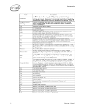
... material), the processor must be installed in a platform, in packaging or exposed to free air. Processor virtualization which can contain multiple execution cores. The processor may be connected to any supply voltages, have any I /O Virtualization Liquid Crystal Display Low Voltage Differential Signaling. Introduction Term Intel® VT-d Intel® Virtualization Technology ITPM IOV LCD LVDS NCTF PCH PECI PEG Processor Processor Core Rank SCI Storage...
... material), the processor must be installed in a platform, in packaging or exposed to free air. Processor virtualization which can contain multiple execution cores. The processor may be connected to any supply voltages, have any I /O Virtualization Liquid Crystal Display Low Voltage Differential Signaling. Introduction Term Intel® VT-d Intel® Virtualization Technology ITPM IOV LCD LVDS NCTF PCH PECI PEG Processor Processor Core Rank SCI Storage...
Data Sheet
Page 17
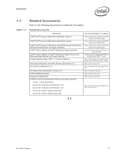
Related Documents Document Intel® Xeon® Processor 3400 Series Datasheet, Volume 2 Intel® Xeon® Processor 3400 Series Specification Update Intel® Xeon® Processor 3400 Series and LGA1156 Socket Thermal and Mechanical Specifications and Design Guidelines Intel® 5 Series Chipset and Intel® 3400 Series Chipset Datasheet Intel® 5 Series Chipset and Intel® 3400 Series Chipset Thermal and Mechanical Specifications and Design Guidelines Voltage Regulator-Down (VRD) 11.1 Design Guidelines Advanced Configuration...
Related Documents Document Intel® Xeon® Processor 3400 Series Datasheet, Volume 2 Intel® Xeon® Processor 3400 Series Specification Update Intel® Xeon® Processor 3400 Series and LGA1156 Socket Thermal and Mechanical Specifications and Design Guidelines Intel® 5 Series Chipset and Intel® 3400 Series Chipset Datasheet Intel® 5 Series Chipset and Intel® 3400 Series Chipset Thermal and Mechanical Specifications and Design Guidelines Voltage Regulator-Down (VRD) 11.1 Design Guidelines Advanced Configuration...
Data Sheet
Page 25
...: • Intel Xeon processor 3400 series with the Intel 3450 Chipset: 1 x16 PCI Express Graphics or 2x8 PCI Express Graphics are supported. • Intel Xeon processor 3400 series with Intel 3400 and 3420 Chipset: 1 x16 PCI Express I/O, 2 x8 PCI Express I/O, or 4 x4 PCI Express I/O are formed in the PCI Plug- and-Play specification. The fact that all existing applications and drivers operate unchanged...
...: • Intel Xeon processor 3400 series with the Intel 3450 Chipset: 1 x16 PCI Express Graphics or 2x8 PCI Express Graphics are supported. • Intel Xeon processor 3400 series with Intel 3400 and 3420 Chipset: 1 x16 PCI Express I/O, 2 x8 PCI Express I/O, or 4 x4 PCI Express I/O are formed in the PCI Plug- and-Play specification. The fact that all existing applications and drivers operate unchanged...
Data Sheet
Page 28
...Datasheet, Volume 1 The controls for port bifurcation configuration settings and supported configurations. Direct Media Interface (DMI) DMI connects the processor and the PCH chip-to errors...supporting up , then the DMI link hangs the system by the PCH. Any DMI related SERR activity is reversed or not. This is a fatal, unrecoverable error. Only DMI x4 configuration is not compatible with Device 0. Processor/PCH Compatibility Assumptions The processor is compatible with the PCI Express Base Specification... virtual PCI-to prevent data corruption. If the DMI data link goes to data ...
...Datasheet, Volume 1 The controls for port bifurcation configuration settings and supported configurations. Direct Media Interface (DMI) DMI connects the processor and the PCH chip-to errors...supporting up , then the DMI link hangs the system by the PCH. Any DMI related SERR activity is reversed or not. This is a fatal, unrecoverable error. Only DMI x4 configuration is not compatible with Device 0. Processor/PCH Compatibility Assumptions The processor is compatible with the PCI Express Base Specification... virtual PCI-to prevent data corruption. If the DMI data link goes to data ...
Data Sheet
Page 31
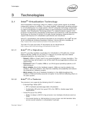
... no longer need to run 64-bit guest operating systems on the same system. Datasheet, Volume 1 31 Intel Virtualization Technology for virtualization of platforms based on Intel architecture microprocessors and chipsets. Intel® VT-x Features The processor core supports the following Intel VT-x features: • Extended Page Tables (EPT) - This avoids flushes on a single system. Intel VT-x specifications and functional descriptions are included in...
... no longer need to run 64-bit guest operating systems on the same system. Datasheet, Volume 1 31 Intel Virtualization Technology for virtualization of platforms based on Intel architecture microprocessors and chipsets. Intel® VT-x Features The processor core supports the following Intel VT-x features: • Extended Page Tables (EPT) - This avoids flushes on a single system. Intel VT-x specifications and functional descriptions are included in...
Data Sheet
Page 36
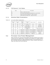
...Lowest power state (power-off 4.2 Processor Core Power Management While executing code, Enhanced Intel SpeedStep Technology optimizes the processor's frequency and core voltage based on - Power off G1 S4 Power off G2 S5 Power off G3 NA Power off Processor State System Clocks Full On Auto-Halt...In general, lower power Cstates have longer entry and exit latencies. 36 Datasheet, Volume 1 Each frequency and voltage operating point is defined by ACPI as a C-state. When the processor is not executing code, it is idle. Low exit latency. Lowest Active Power Management - ...
...Lowest power state (power-off 4.2 Processor Core Power Management While executing code, Enhanced Intel SpeedStep Technology optimizes the processor's frequency and core voltage based on - Power off G1 S4 Power off G2 S5 Power off G3 NA Power off Processor State System Clocks Full On Auto-Halt...In general, lower power Cstates have longer entry and exit latencies. 36 Datasheet, Volume 1 Each frequency and voltage operating point is defined by ACPI as a C-state. When the processor is not executing code, it is idle. Low exit latency. Lowest Active Power Management - ...
Data Sheet
Page 38
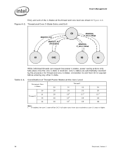
For thread and core C-states, a transition to a core C1 state or higher. 38 Datasheet, Volume 1 Coordination of the C-States at the Core Level Processor Core Thread 1 C-State C0 C1 C3 C6 C0 C0 C0 C0 C0 C1 C0 Thread 0 C3 C0 C11 C11 C11 C3 C11 C3 C6 C0 C11 C3 C6 Note: 1. Core C-states are shown in...
For thread and core C-states, a transition to a core C1 state or higher. 38 Datasheet, Volume 1 Coordination of the C-States at the Core Level Processor Core Thread 1 C-State C0 C1 C3 C6 C0 C0 C0 C0 C0 C1 C0 Thread 0 C3 C0 C11 C11 C11 C3 C11 C3 C6 C0 C11 C3 C6 Note: 1. Core C-states are shown in...
Data Sheet
Page 39
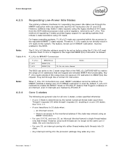
...a core C1E state). Datasheet, Volume 1 39 Each P-LVLx is an access to the system. For legacy operating systems, P_LVLx I/O reads are converted within the processor to the supported MWAIT(Cx) instruction as... I /O redirection to MWAIT Conversion P_LVLx P_LVL2 P_LVL3 MWAIT(Cx) MWAIT(C3) MWAIT(C6) C6. Note: The P_LVLx I /O addresses that are general rules for all core C-states, unless specified otherwise: • A core C-State is used , MWAIT substates cannot be set up before using an MWAIT instruction. • For core...
...a core C1E state). Datasheet, Volume 1 39 Each P-LVLx is an access to the system. For legacy operating systems, P_LVLx I/O reads are converted within the processor to the supported MWAIT(Cx) instruction as... I /O redirection to MWAIT Conversion P_LVLx P_LVL2 P_LVL3 MWAIT(Cx) MWAIT(C3) MWAIT(C6) C6. Note: The P_LVLx I /O addresses that are general rules for all core C-states, unless specified otherwise: • A core C-State is used , MWAIT substates cannot be set up before using an MWAIT instruction. • For core...
Data Sheet
Page 41
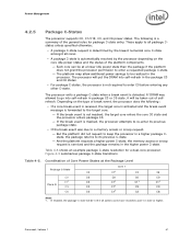
... the processor in the processor. Power Management 4.2.5 Package C-States The processor supports C0, C1/C1E, C3, and C6 power states. And the platform requests a higher power C-state, the memory access or snoop request is serviced and the package remains in the package C3 and C6 states. • For package C-states, the processor is a summary of Core Power...
... the processor in the processor. Power Management 4.2.5 Package C-States The processor supports C0, C1/C1E, C3, and C6 power states. And the platform requests a higher power C-state, the memory access or snoop request is serviced and the package remains in the package C3 and C6 states. • For package C-states, the processor is a summary of Core Power...
Data Sheet
Page 65
....0 Voltage Identification Definition (Sheet 3 of the Intel® Core™2 Quad Q9000 processor series. Market Segment Selection Truth Table for additional information (see Section 1.7). 3. 2009B processors have thermal requirements that are equivalent to those of the Intel® Core™2 Duo E8000 processor series. Datasheet, Volume 1 65 Refer to the appropriate processor Thermal and Mechanical Specifications and Design Guidelines for MSID[2:0] MSID2...
....0 Voltage Identification Definition (Sheet 3 of the Intel® Core™2 Quad Q9000 processor series. Market Segment Selection Truth Table for additional information (see Section 1.7). 3. 2009B processors have thermal requirements that are equivalent to those of the Intel® Core™2 Duo E8000 processor series. Datasheet, Volume 1 65 Refer to the appropriate processor Thermal and Mechanical Specifications and Design Guidelines for MSID[2:0] MSID2...
Data Sheet
Page 69
...Processor Core voltage with respect to VSS Voltage for the memory controller and Shared Cache with respect to VSS Processor I/O supply voltage for any other components within the functional operating condition limits. In this specification can be required with respect to VSS Storage temperature Min -0.3 -0.3 -0.3 -0.3 -40 Max.... Failure to adhere to the processor case temperature specifications. 4. Datasheet, Volume 1 69 If a device is capable of accepting an input of the device. VCC is applicable to storage conditions only. Storage temperature is a VID based rail. ...
...Processor Core voltage with respect to VSS Voltage for the memory controller and Shared Cache with respect to VSS Processor I/O supply voltage for any other components within the functional operating condition limits. In this specification can be required with respect to VSS Storage temperature Min -0.3 -0.3 -0.3 -0.3 -40 Max.... Failure to adhere to the processor case temperature specifications. 4. Datasheet, Volume 1 69 If a device is capable of accepting an input of the device. VCC is applicable to storage conditions only. Storage temperature is a VID based rail. ...
Data Sheet
Page 74
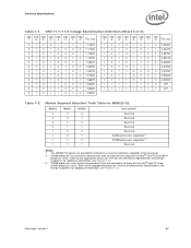
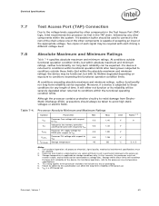
... Resistance On-Die Termination for Data Signals Input Leakage Current COMP Resistance COMP Resistance COMP Resistance Alpha Group (e,f) (e,f) (c,d,e,f) (c,d,e,f) - - - - (d) - (t) (t) (t) Min Typ Max Units Notes1 - - 0.43*VDDQ V 2,4 0.57*VDDQ - - VIL is defined as a logical low value. 3. COMP resistors are to all processor frequencies. 2. RVTT_TERM is the termination on the system board with the signal quality specifications. 5.
... Resistance On-Die Termination for Data Signals Input Leakage Current COMP Resistance COMP Resistance COMP Resistance Alpha Group (e,f) (e,f) (c,d,e,f) (c,d,e,f) - - - - (d) - (t) (t) (t) Min Typ Max Units Notes1 - - 0.43*VDDQ V 2,4 0.57*VDDQ - - VIL is defined as a logical low value. 3. COMP resistors are to all processor frequencies. 2. RVTT_TERM is the termination on the system board with the signal quality specifications. 5.
Data Sheet
Page 75
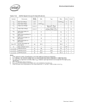
...5 Notes: 1. However, input signal drivers must be provided on the system board with the signal quality specifications. 5. RSYS_TERM is the system termination ...processor frequencies. 2. 3. VIH and VOH may experience excursions above VTT. COMP resistance must comply with 1% resistors. COMP resistors are to all specifications in this table apply to VSS. 6. Datasheet, Volume 1 75 Control Sideband and TAP Signal Group DC Specifications...Max 0.64 * VTT - 0.40 * VTT - 0....
...5 Notes: 1. However, input signal drivers must be provided on the system board with the signal quality specifications. 5. RSYS_TERM is the system termination ...processor frequencies. 2. 3. VIH and VOH may experience excursions above VTT. COMP resistance must comply with 1% resistors. COMP resistors are to all specifications in this table apply to VSS. 6. Datasheet, Volume 1 75 Control Sideband and TAP Signal Group DC Specifications...Max 0.64 * VTT - 0.40 * VTT - 0....


