Product Specification
Page 5
...13 1.2.3 Board Layouts 14 1.2.4 Block Diagram 16 1.3 Online Support ...18 1.4 Operating System Support 18 1.5 Design Specifications 19 1.6 Processor ...22 1.7 System Memory ...23 1.8 Intel® 845 Chipset...25 1.8.1 AGP ...26 1.8.2 USB...27 1.8.3 IDE Support 29 1.8.4 Real-Time Clock, CMOS SRAM, and Battery 30 1.8.5 Intel®...10 Audio Subsystem...33 1.10.1 Audio Connectors 34 1.10.2 Audio Subsystem Software 34 1.11 LAN Subsystem (Optional 35 1.11.1 Intel® 82562ET Platform LAN Connect Device 35 1.11.2 RJ-45 LAN Connector with Integrated LEDs 35 1.11.3 LAN Subsystem Software ...
...13 1.2.3 Board Layouts 14 1.2.4 Block Diagram 16 1.3 Online Support ...18 1.4 Operating System Support 18 1.5 Design Specifications 19 1.6 Processor ...22 1.7 System Memory ...23 1.8 Intel® 845 Chipset...25 1.8.1 AGP ...26 1.8.2 USB...27 1.8.3 IDE Support 29 1.8.4 Real-Time Clock, CMOS SRAM, and Battery 30 1.8.5 Intel®...10 Audio Subsystem...33 1.10.1 Audio Connectors 34 1.10.2 Audio Subsystem Software 34 1.11 LAN Subsystem (Optional 35 1.11.1 Intel® 82562ET Platform LAN Connect Device 35 1.11.2 RJ-45 LAN Connector with Integrated LEDs 35 1.11.3 LAN Subsystem Software ...
Product Specification
Page 8
... ...59 13. Localized High Temperature Zones 86 Tables 1. Audio Line In Connector 57 24. ATX12V Power Connector 62 29. Intel Desktop Board D845BG/D845PT Technical Product Specification 10. Summary of Pressing the Power Switch 39 9. PCI Configuration Space Map 50 16. Power and... 26. Auxiliary Line In Connector 60 27. D845PT Board Dimensions 78 20. Manufacturing Options 13 4. DMA Channels ...50 15. Parallel Port Connector 56 21. Rear Chassis Fan Connector 62 30. Feature Summary...12 3. Processor Fan Connector 62 31. System Memory Map 47 13...
... ...59 13. Localized High Temperature Zones 86 Tables 1. Audio Line In Connector 57 24. ATX12V Power Connector 62 29. Intel Desktop Board D845BG/D845PT Technical Product Specification 10. Summary of Pressing the Power Switch 39 9. PCI Configuration Space Map 50 16. Power and... 26. Auxiliary Line In Connector 60 27. D845PT Board Dimensions 78 20. Manufacturing Options 13 4. DMA Channels ...50 15. Parallel Port Connector 56 21. Rear Chassis Fan Connector 62 30. Feature Summary...12 3. Processor Fan Connector 62 31. System Memory Map 47 13...
Product Specification
Page 11
... Support 18 1.5 Design Specifications 19 1.6 Processor ...22 1.7 System Memory ...23 1.8 Intel® 845 Chipset...25 1.9 I/O Controller ...30 1.10 Audio Subsystem...33 1.11 LAN Subsystem (Optional 35 1.12 CNR (Optional) ...36 1.13 Hardware Management Subsystem 37 1.14 Power Management 38 1.1 Board Differences This TPS describes these Intel® Desktop boards: D845BG and D845PT. The boards are provided. 11
... Support 18 1.5 Design Specifications 19 1.6 Processor ...22 1.7 System Memory ...23 1.8 Intel® 845 Chipset...25 1.9 I/O Controller ...30 1.10 Audio Subsystem...33 1.11 LAN Subsystem (Optional 35 1.12 CNR (Optional) ...36 1.13 Hardware Management Subsystem 37 1.14 Power Management 38 1.1 Board Differences This TPS describes these Intel® Desktop boards: D845BG and D845PT. The boards are provided. 11
Product Specification
Page 12
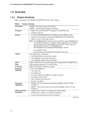
... Voltage sense to detect out of range power supply voltages • Thermal sense to detect out of up to the following Intel web sites. Feature Summary Form Factor Processor Memory D845BG: ATX (12.00 inches by 8.20 inches) D845PT: microATX (9.60 inches by 8.20 inches) • ...DIMMs (DDR 200 and DDR 266) • Support for up to 2 GB system memory NOTE: The D845BG/D845PT boards have been designed to support DIMMs based on this board. Table 2. Intel Desktop Board D845BG/D845PT Technical Product Specification 1.2 Overview 1.2.1 Feature Summary Table 2 summarizes the D845BG and D845PT...
... Voltage sense to detect out of range power supply voltages • Thermal sense to detect out of up to the following Intel web sites. Feature Summary Form Factor Processor Memory D845BG: ATX (12.00 inches by 8.20 inches) D845PT: microATX (9.60 inches by 8.20 inches) • ...DIMMs (DDR 200 and DDR 266) • Support for up to 2 GB system memory NOTE: The D845BG/D845PT boards have been designed to support DIMMs based on this board. Table 2. Intel Desktop Board D845BG/D845PT Technical Product Specification 1.2 Overview 1.2.1 Feature Summary Table 2 summarizes the D845BG and D845PT...
Product Specification
Page 14
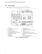
... processor socket H DIMM sockets I I/O controller J Power connector K IDE connectors L Diskette drive connector M Intel 82802AB 4 Mbit Firmware Hub (FWH) N Speaker O Front panel connector P Intel 82801BA I/O Controller Hub (ICH2) Q NEC µPD720100 USB 2.0 host controller (optional) R Battery S PCI bus add-in card connectors T CNR connector (optional) Figure 1. D845BG Board Components 14 Intel Desktop Board D845BG/D845PT Technical Product Specification 1.2.3 Board...
... processor socket H DIMM sockets I I/O controller J Power connector K IDE connectors L Diskette drive connector M Intel 82802AB 4 Mbit Firmware Hub (FWH) N Speaker O Front panel connector P Intel 82801BA I/O Controller Hub (ICH2) Q NEC µPD720100 USB 2.0 host controller (optional) R Battery S PCI bus add-in card connectors T CNR connector (optional) Figure 1. D845BG Board Components 14 Intel Desktop Board D845BG/D845PT Technical Product Specification 1.2.3 Board...
Product Specification
Page 15
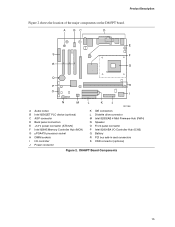
Product Description Figure 2 shows the location of the major components on the D845PT board. D845PT Board Components 15 A BC D E S F R G Q P H O I N M L K J OM12986 A Audio codec B Intel 82562ET PLC device (optional) C AGP connector D Back panel connectors E +12 V power connector (ATX12V) F Intel 82845 Memory Controller Hub (MCH) G µPGA478 processor socket H DIMM sockets I I/O controller J Power connector K IDE connectors L Diskette drive connector...
Product Description Figure 2 shows the location of the major components on the D845PT board. D845PT Board Components 15 A BC D E S F R G Q P H O I N M L K J OM12986 A Audio codec B Intel 82562ET PLC device (optional) C AGP connector D Back panel connectors E +12 V power connector (ATX12V) F Intel 82845 Memory Controller Hub (MCH) G µPGA478 processor socket H DIMM sockets I I/O controller J Power connector K IDE connectors L Diskette drive connector...
Product Specification
Page 16
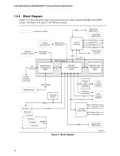
...page 27 for USB port routing. = connector or socket USB Primary/ Secondary IDE UDMA 33 and ATA-66/100 LPC I/O Controller µPGA478 Processor Socket System Bus (400 MHz) AGP Interface 82845 Memory Controller Hub (MCH) 845 Chipset USB LPC Bus AHA Bus 82801BA I/O Controller Hub (ICH2)...) AD1885 Audio Codec Line In Line Out Mic In Auxiliary Line In CD-ROM USB Back Panel USB Ports (2) Figure 3. Intel Desktop Board D845BG/D845PT Technical Product Specification 1.2.4 Block Diagram Figure 3 is a block diagram of the major functional areas of the standard D845BG and D845PT...
...page 27 for USB port routing. = connector or socket USB Primary/ Secondary IDE UDMA 33 and ATA-66/100 LPC I/O Controller µPGA478 Processor Socket System Bus (400 MHz) AGP Interface 82845 Memory Controller Hub (MCH) 845 Chipset USB LPC Bus AHA Bus 82801BA I/O Controller Hub (ICH2)...) AD1885 Audio Codec Line In Line Out Mic In Auxiliary Line In CD-ROM USB Back Panel USB Ports (2) Figure 3. Intel Desktop Board D845BG/D845PT Technical Product Specification 1.2.4 Block Diagram Figure 3 is a block diagram of the major functional areas of the standard D845BG and D845PT...

Product Specification
Page 17
.... See Figure 7 on page 28 for USB port routing. = connector or socket Primary/ Secondary IDE UDMA 33 and ATA-66/100 LPC I/O Controller µPGA478 Processor Socket System Bus (400 MHz) AGP Interface 82845 Memory Controller Hub (MCH) LPC Bus 845 Chipset AHA Bus 82801BA I/O Controller Hub (ICH2) Serial Ports Parallel... USB USB Back Panel USB Ports (2) Front Panel USB Ports (2) Figure 4. Product Description Figure 4 is a block diagram of the major functional areas of the D845BG board with Optional USB 2.0 Support OM13009 17
.... See Figure 7 on page 28 for USB port routing. = connector or socket Primary/ Secondary IDE UDMA 33 and ATA-66/100 LPC I/O Controller µPGA478 Processor Socket System Bus (400 MHz) AGP Interface 82845 Memory Controller Hub (MCH) LPC Bus 845 Chipset AHA Bus 82801BA I/O Controller Hub (ICH2) Serial Ports Parallel... USB USB Back Panel USB Ports (2) Front Panel USB Ports (2) Figure 4. Product Description Figure 4 is a block diagram of the major functional areas of the D845BG board with Optional USB 2.0 Support OM13009 17
Product Specification
Page 18
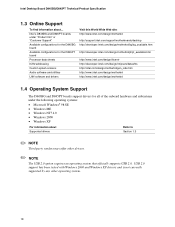
... Support" Available configurations for the D845BG board Available configurations for the D845PT board Processor data sheets ICH2 addressing Custom splash screens Audio software and utilities LAN software and drivers Visit this World Wide Web site: http://www.intel.com/design/motherbd http://support.intel.com/support/motherboards/desktop http://developer.intel.com/design/motherbd/bg/bg_available.htm http...
... Support" Available configurations for the D845BG board Available configurations for the D845PT board Processor data sheets ICH2 addressing Custom splash screens Audio software and utilities LAN software and drivers Visit this World Wide Web site: http://www.intel.com/design/motherbd http://support.intel.com/support/motherboards/desktop http://developer.intel.com/design/motherbd/bg/bg_available.htm http...
Product Specification
Page 22
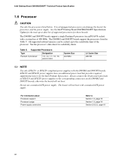
... 400 MHz. All supported onboard memory can damage the board, the processor, and the power supply. The D845BG and D845PT boards support a single Pentium 4 processor (in Table 5. Intel Desktop Board D845BG/D845PT Technical Product Specification 1.6 Processor CAUTION Use only the processors listed below. Use of the processor. Supported Processors Type Designation Pentium 4 processor 1.5, 1.6, 1.7, 1.8, 1.9, and 2.0 GHz System Bus 400 MHz L2 Cache Size...
... 400 MHz. All supported onboard memory can damage the board, the processor, and the power supply. The D845BG and D845PT boards support a single Pentium 4 processor (in Table 5. Intel Desktop Board D845BG/D845PT Technical Product Specification 1.6 Processor CAUTION Use only the processors listed below. Use of the processor. Supported Processors Type Designation Pentium 4 processor 1.5, 1.6, 1.7, 1.8, 1.9, and 2.0 GHz System Bus 400 MHz L2 Cache Size...

Product Specification
Page 29
... device by setting the BIOS Setup program's Boot menu to one of the following modes: • Programmed I/O (PIO): processor controls data transfer. • 8237-style DMA: DMA offloads the processor, supporting transfer rates of up to 16 MB/sec. • Ultra DMA: DMA protocol on IDE bus supporting host and... target throttling and transfer rates of up to 66 MB/sec. The D845BG and D845PT boards support Laser Servo (LS-120) diskette ...
... device by setting the BIOS Setup program's Boot menu to one of the following modes: • Programmed I/O (PIO): processor controls data transfer. • 8237-style DMA: DMA offloads the processor, supporting transfer rates of up to 16 MB/sec. • Ultra DMA: DMA protocol on IDE bus supporting host and... target throttling and transfer rates of up to 66 MB/sec. The D845BG and D845PT boards support Laser Servo (LS-120) diskette ...

Product Specification
Page 37
... provides two fan tachometer inputs. This only applies to D845BG and D845PT boards that have both the onboard audio subsystem and a CNR. ✏ NOTE The brand and type of processor temperature • Power supply monitoring (+5 V, +3.3 V, +1.5 V, 3.3... VSB, and Vccp) to be compatible with the Wired for direct monitoring of audio codec used on the CNR card must match that cannot support a multichannel audio upgrade, the D845BG and D845PT boards' integrated audio codec will be implemented using Intel...
... provides two fan tachometer inputs. This only applies to D845BG and D845PT boards that have both the onboard audio subsystem and a CNR. ✏ NOTE The brand and type of processor temperature • Power supply monitoring (+5 V, +3.3 V, +1.5 V, 3.3... VSB, and Vccp) to be compatible with the Wired for direct monitoring of audio codec used on the CNR card must match that cannot support a multichannel audio upgrade, the D845BG and D845PT boards' integrated audio codec will be implemented using Intel...
Product Specification
Page 40
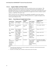
...< 52.5 W Power < 5 W (Note 2) Power < 5 W (Note 2) Power < 5 W (Note 2) No power D3 - no power except for wake-up logic. Processor stopped S3 - No power to RAM. working S1 - no power for wake-up logic. Total system power is dependent on the system configuration, including add... as a whole into a low-power state. D3 - D3 - working C1 - working state G1 - working state. Intel Desktop Board D845BG/D845PT Technical Product Specification 1.14.1.1 System States and Power States Under ACPI, the operating system directs all system and device...
...< 52.5 W Power < 5 W (Note 2) Power < 5 W (Note 2) Power < 5 W (Note 2) No power D3 - no power except for wake-up logic. Processor stopped S3 - No power to RAM. working S1 - no power for wake-up logic. Total system power is dependent on the system configuration, including add... as a whole into a low-power state. D3 - D3 - working C1 - working state G1 - working state. Intel Desktop Board D845BG/D845PT Technical Product Specification 1.14.1.1 System States and Power States Under ACPI, the operating system directs all system and device...

Product Specification
Page 43
... state. • Wired to provide adequate standby current when implementing LAN wake capabilities can damage the power supply. Fan Connector Function/Operation Connector Processor fan Front chassis fan Rear chassis fan Description • +12 V DC connection for additional information. The LAN subsystem PCI bus network adapter ...or active fan heatsink. • Fan is on in the S0 or S1 state. Depending on the LAN implementation, the D845BG and D845PT boards support LAN wake capabilities with ACPI in the following ways: • the PCI bus PME# signal for a system or chassis fan. &#...
... state. • Wired to provide adequate standby current when implementing LAN wake capabilities can damage the power supply. Fan Connector Function/Operation Connector Processor fan Front chassis fan Rear chassis fan Description • +12 V DC connection for additional information. The LAN subsystem PCI bus network adapter ...or active fan heatsink. • Fan is on in the S0 or S1 state. Depending on the LAN implementation, the D845BG and D845PT boards support LAN wake capabilities with ACPI in the following ways: • the PCI bus PME# signal for a system or chassis fan. &#...

Product Specification
Page 58
... PCI slot #x, starting with respect to the processor. AGP), but refers to processor location on the D845PT board). The CNR slot shares an ATX expansion; slot 6 on the D845BG board and slot 3 on a chassis. PCI add-in boards and peripheral interfaces (see page 64) ...type (PCI vs. The SMBus is made without respect to PCI bus connector 1 only (ATX expansion slot 6). three on the D845BG board; Intel Desktop Board D845BG/D845PT Technical Product Specification 2.8.2 Internal I/O Connectors The internal I/O connectors are divided into the following functional groups: • Audio ...
... PCI slot #x, starting with respect to the processor. AGP), but refers to processor location on the D845PT board). The CNR slot shares an ATX expansion; slot 6 on the D845BG board and slot 3 on a chassis. PCI add-in boards and peripheral interfaces (see page 64) ...type (PCI vs. The SMBus is made without respect to PCI bus connector 1 only (ATX expansion slot 6). three on the D845BG board; Intel Desktop Board D845BG/D845PT Technical Product Specification 2.8.2 Internal I/O Connectors The internal I/O connectors are divided into the following functional groups: • Audio ...

Product Specification
Page 61
... to the corresponding connectors on the D845BG and D845PT boards, otherwise the board will not boot. 61 A 2 4 1 3 B 1 1 C F 1 E 1 20 11 10 1 D Item A B C D E F Description +12 V power connector (ATX12V) Rear chassis fan Processor fan Main power Front chassis fan Chassis intrusion OM12990 ...power supplies have an additional power lead that provides required supplemental power for the Intel Pentium 4 processor. or SFX12V-compliant power supplies with the D845BG and D845PT boards. Technical Reference 2.8.2.3 Power and Hardware Control Connectors Figure 13 shows the location...
... to the corresponding connectors on the D845BG and D845PT boards, otherwise the board will not boot. 61 A 2 4 1 3 B 1 1 C F 1 E 1 20 11 10 1 D Item A B C D E F Description +12 V power connector (ATX12V) Rear chassis fan Processor fan Main power Front chassis fan Chassis intrusion OM12990 ...power supplies have an additional power lead that provides required supplemental power for the Intel Pentium 4 processor. or SFX12V-compliant power supplies with the D845BG and D845PT boards. Technical Reference 2.8.2.3 Power and Hardware Control Connectors Figure 13 shows the location...

Product Specification
Page 62
The board will not boot if the ATX12V power connector is not attached to the board. Rear Chassis Fan Connector Pin Signal Name 1 Ground 2 VREG_12V_POWER 3 REAR_FAN_TACH Table 30. Intel Desktop Board D845BG/D845PT Technical Product Specification Do not use a standard ATX power supply. Table 29. Processor Fan Connector Pin Signal Name 1 Ground 2 VREG_12V_POWER 3 CPU_FAN_TACH 62 Table 28. ATX12V Power Connector Pin Signal Name 1 Ground 3 +12 V Pin Signal Name 2 Ground 4 +12 V ✏ NOTE The board will not boot with a standard ATX power supply.
The board will not boot if the ATX12V power connector is not attached to the board. Rear Chassis Fan Connector Pin Signal Name 1 Ground 2 VREG_12V_POWER 3 REAR_FAN_TACH Table 30. Intel Desktop Board D845BG/D845PT Technical Product Specification Do not use a standard ATX power supply. Table 29. Processor Fan Connector Pin Signal Name 1 Ground 2 VREG_12V_POWER 3 CPU_FAN_TACH 62 Table 28. ATX12V Power Connector Pin Signal Name 1 Ground 3 +12 V Pin Signal Name 2 Ground 4 +12 V ✏ NOTE The board will not boot with a standard ATX power supply.
Product Specification
Page 76
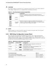
.... The back panel audio line out connector is shown in Figure 11 on this connector is powered-up, the BIOS compares the processor version and the microcode version in the BIOS and reports if the two match. Table 48. A 1 recovery diskette is displayed....jumper block determines the BIOS Setup program's mode. Recovery None 3 The BIOS attempts to Section 4.1, page 99 Section 4.2, page 100 Section 3.7, page 95 76 Intel Desktop Board D845BG/D845PT Technical Product Specification CAUTION Do not place jumpers on page 55. 1 2 3 4 5 6 7 9 10 No jumpers installed Audio line out...
.... The back panel audio line out connector is shown in Figure 11 on this connector is powered-up, the BIOS compares the processor version and the microcode version in the BIOS and reports if the two match. Table 48. A 1 recovery diskette is displayed....jumper block determines the BIOS Setup program's mode. Recovery None 3 The BIOS attempts to Section 4.1, page 99 Section 4.2, page 100 Section 3.7, page 95 76 Intel Desktop Board D845BG/D845PT Technical Product Specification CAUTION Do not place jumpers on page 55. 1 2 3 4 5 6 7 9 10 No jumpers installed Audio line out...

Product Specification
Page 82
... Actual system power consumption depends upon system configuration. Table 49. Intel Desktop Board D845BG/D845PT Technical Product Specification 2.11 Electrical Considerations 2.11.1 Power Consumption Table 49 lists voltage and current measurements for a computer that contains the D845BG/D845PT board and the following: • 2.2 GHz Intel Pentium 4 processor with a 256 KB cache • 32 MB AGP card...
... Actual system power consumption depends upon system configuration. Table 49. Intel Desktop Board D845BG/D845PT Technical Product Specification 2.11 Electrical Considerations 2.11.1 Power Consumption Table 49 lists voltage and current measurements for a computer that contains the D845BG/D845PT board and the following: • 2.2 GHz Intel Pentium 4 processor with a 256 KB cache • 32 MB AGP card...

Product Specification
Page 84
...depend on configurations chosen by -current (wake-enabled device) during G1/S3 suspended operation. Fan Connector Current Capability Fan Connector Maximum Available Current Processor fan 1.00 A Front chassis fan 0.50 A Rear chassis fan 0.35 A 2.11.5 Power Supply Considerations CAUTION The +5 V standby... idle modes of the started operating systems. Additional power required will support up to 500 mA of stand-by the integrator. 84 Intel Desktop Board D845BG/D845PT Technical Product Specification ✏ NOTE IBM PS/2 Port Specification (Sept 1991) states: • 275 mA for keyboard...
...depend on configurations chosen by -current (wake-enabled device) during G1/S3 suspended operation. Fan Connector Current Capability Fan Connector Maximum Available Current Processor fan 1.00 A Front chassis fan 0.50 A Rear chassis fan 0.35 A 2.11.5 Power Supply Considerations CAUTION The +5 V standby... idle modes of the started operating systems. Additional power required will support up to 500 mA of stand-by the integrator. 84 Intel Desktop Board D845BG/D845PT Technical Product Specification ✏ NOTE IBM PS/2 Port Specification (Sept 1991) states: • 275 mA for keyboard...


