Product Specification
Page 7
... Menu ...114 4.6 Power Menu ...115 4.6.1 ACPI Submenu 116 4.7 Boot Menu ...117 4.7.1 Boot Device Priority Submenu 118 4.7.2 Hard Disk Drives Submenu 119 4.7.3 Removable Devices Submenu 119 4.7.4 ATAPI CD-ROM Drives Submenu 120 4.8 Exit Menu ...120 5 Error Messages and Beep Codes 5.1 BIOS Error Messages 121 5.2 Port 80h POST Codes 123 5.3 Bus Initialization Checkpoints 127 5.4 Speaker ...128 5.5 BIOS Beep Codes ...128 Figures 1. USB 2.0 Port Configuration (Optional 28 8. ICH2 and CNR Signal Interface 36 vii D845PT Board Components 15 3. Block Diagram ...16 4. D845BG Board...
... Menu ...114 4.6 Power Menu ...115 4.6.1 ACPI Submenu 116 4.7 Boot Menu ...117 4.7.1 Boot Device Priority Submenu 118 4.7.2 Hard Disk Drives Submenu 119 4.7.3 Removable Devices Submenu 119 4.7.4 ATAPI CD-ROM Drives Submenu 120 4.8 Exit Menu ...120 5 Error Messages and Beep Codes 5.1 BIOS Error Messages 121 5.2 Port 80h POST Codes 123 5.3 Bus Initialization Checkpoints 127 5.4 Speaker ...128 5.5 BIOS Beep Codes ...128 Figures 1. USB 2.0 Port Configuration (Optional 28 8. ICH2 and CNR Signal Interface 36 vii D845PT Board Components 15 3. Block Diagram ...16 4. D845BG Board...
Product Specification
Page 8
... Options 13 4. Auxiliary Line In Connector 60 27. D845PT Board Dimensions 78 20. Supported Memory Configurations 24 7. Interrupts ...51 17. Mic In Connector ...57 26. External I /O Map ...48 14. Localized High Temperature Zones 86 Tables 1. Feature Summary...12 3. Serial Port A Connector 57 22. Main Power Connector 63 viii Processor Fan Connector 62 31. Audio Line In Connector 57 24. Back Panel Connectors 55 12. LAN Connector (Optional 57 23. Intel Desktop Board D845BG/D845PT Technical Product Specification 10. System Memory...
... Options 13 4. Auxiliary Line In Connector 60 27. D845PT Board Dimensions 78 20. Supported Memory Configurations 24 7. Interrupts ...51 17. Mic In Connector ...57 26. External I /O Map ...48 14. Localized High Temperature Zones 86 Tables 1. Feature Summary...12 3. Serial Port A Connector 57 22. Main Power Connector 63 viii Processor Fan Connector 62 31. Audio Line In Connector 57 24. Back Panel Connectors 55 12. LAN Connector (Optional 57 23. Intel Desktop Board D845BG/D845PT Technical Product Specification 10. System Memory...
Product Specification
Page 9
.... PCI IDE Connectors 70 39. D845BG/D845PT Board Environmental Specifications 87 54. Video Configuration Submenu 113 71. Front Panel Audio Connector/Jumper Block 76 48. Safety Regulations ...88 55. Extended Configuration Submenu 101 61. Boot Configuration Submenu 105 65. Security Menu ...114 72. Main Menu...102 62. Boot Device Priority Submenu 118 76. Hard Disk Drives Submenu 119 77. EMC Regulations...88 56. BIOS Setup Program Function Keys 100 59. Diskette Configuration Submenu 111 69. Removable Devices Submenu...
.... PCI IDE Connectors 70 39. D845BG/D845PT Board Environmental Specifications 87 54. Video Configuration Submenu 113 71. Front Panel Audio Connector/Jumper Block 76 48. Safety Regulations ...88 55. Extended Configuration Submenu 101 61. Boot Configuration Submenu 105 65. Security Menu ...114 72. Main Menu...102 62. Boot Device Priority Submenu 118 76. Hard Disk Drives Submenu 119 77. EMC Regulations...88 56. BIOS Setup Program Function Keys 100 59. Diskette Configuration Submenu 111 69. Removable Devices Submenu...
Product Specification
Page 12
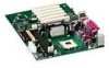
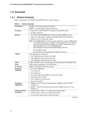
... I/O Controller Hub (ICH2) • Intel® 82802AB 4 Mbit Firmware Hub (FWH) Audio subsystem for a maximum onboard capacity of up to 2 GB system memory NOTE: The D845BG/D845PT boards have been designed to support DIMMs based on 512 Mbit technology for AC '97 processing using the Analog Devices AD1885 codec AGP connector supporting 1.5 V 4X AGP cards SMSC LPC47M142 LPC Bus I/O controller • Up to seven USB ports • Two serial ports...
... I/O Controller Hub (ICH2) • Intel® 82802AB 4 Mbit Firmware Hub (FWH) Audio subsystem for a maximum onboard capacity of up to 2 GB system memory NOTE: The D845BG/D845PT boards have been designed to support DIMMs based on 512 Mbit technology for AC '97 processing using the Analog Devices AD1885 codec AGP connector supporting 1.5 V 4X AGP cards SMSC LPC47M142 LPC Bus I/O controller • Up to seven USB ports • Two serial ports...
Product Specification
Page 16
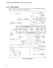
...LPC I/O Controller µPGA478 Processor Socket System Bus (400 MHz) AGP Interface 82845 Memory Controller Hub (MCH) 845 Chipset USB LPC Bus AHA Bus 82801BA I/O Controller Hub (ICH2) Back Panel USB Ports (2) Front Panel USB Ports (2) Serial Ports Parallel Port PS/2 Mouse PS/2 Keyboard Diskette Drive Connector 82802AB 4 Mbit Firmware Hub (FWH) 4X AGP Connector (1.5 V only) DIMM Banks (2) DDR SDRAM Bus Hardware Monitor SMBus PCI Slot 1 PCI Bus PCI Slot 2 PCI Slot 3 PCI Slot 4 PCI Slot 5 PCI Slot 6 D845BG Only Physical Layer Interface (optional) LAN Connector (optional) CSMA...
...LPC I/O Controller µPGA478 Processor Socket System Bus (400 MHz) AGP Interface 82845 Memory Controller Hub (MCH) 845 Chipset USB LPC Bus AHA Bus 82801BA I/O Controller Hub (ICH2) Back Panel USB Ports (2) Front Panel USB Ports (2) Serial Ports Parallel Port PS/2 Mouse PS/2 Keyboard Diskette Drive Connector 82802AB 4 Mbit Firmware Hub (FWH) 4X AGP Connector (1.5 V only) DIMM Banks (2) DDR SDRAM Bus Hardware Monitor SMBus PCI Slot 1 PCI Bus PCI Slot 2 PCI Slot 3 PCI Slot 4 PCI Slot 5 PCI Slot 6 D845BG Only Physical Layer Interface (optional) LAN Connector (optional) CSMA...

Product Specification
Page 17
... page 28 for USB port routing. = connector or socket Primary/ Secondary IDE UDMA 33 and ATA-66/100 LPC I/O Controller µPGA478 Processor Socket System Bus (400 MHz) AGP Interface 82845 Memory Controller Hub (MCH) LPC Bus 845 Chipset AHA Bus 82801BA I/O Controller Hub (ICH2) Serial Ports Parallel Port PS/2 Mouse PS/2 Keyboard Diskette Drive Connector 82802AB 4 Mbit Firmware Hub (FWH) 4X AGP Connector (1.5 V only) DIMM Banks (2) DDR SDRAM Bus Hardware Monitor PCI Slot 1 PCI Slot 2 PCI Slot 3 PCI Slot 4 PCI Slot 5 SMBus PCI Bus CSMA/CD...
... page 28 for USB port routing. = connector or socket Primary/ Secondary IDE UDMA 33 and ATA-66/100 LPC I/O Controller µPGA478 Processor Socket System Bus (400 MHz) AGP Interface 82845 Memory Controller Hub (MCH) LPC Bus 845 Chipset AHA Bus 82801BA I/O Controller Hub (ICH2) Serial Ports Parallel Port PS/2 Mouse PS/2 Keyboard Diskette Drive Connector 82802AB 4 Mbit Firmware Hub (FWH) 4X AGP Connector (1.5 V only) DIMM Banks (2) DDR SDRAM Bus Hardware Monitor PCI Slot 1 PCI Slot 2 PCI Slot 3 PCI Slot 4 PCI Slot 5 SMBus PCI Bus CSMA/CD...

Product Specification
Page 29
... Ultra DMA and is device driver compatible. • ATA-100: DMA protocol on page 109. floppy disk drive) • ARMD-HDD (ATAPI removable media device - Product Description 1.8.3 IDE Support 1.8.3.1 IDE Interfaces The ICH2's IDE controller has two independent bus-mastering IDE interfaces that allows an add-in SCSI controller to use the same LED as the onboard IDE controller. The IDE interfaces support the following : • ARMD-FDD (ATAPI removable media device - The BIOS supports Logical Block Addressing...
... Ultra DMA and is device driver compatible. • ATA-100: DMA protocol on page 109. floppy disk drive) • ARMD-HDD (ATAPI removable media device - Product Description 1.8.3 IDE Support 1.8.3.1 IDE Interfaces The ICH2's IDE controller has two independent bus-mastering IDE interfaces that allows an add-in SCSI controller to use the same LED as the onboard IDE controller. The IDE interfaces support the following : • ARMD-FDD (ATAPI removable media device - The BIOS supports Logical Block Addressing...

Product Specification
Page 36
... CNR (Optional) The CNR connector provides an interface that supports the audio, modem, USB, and LAN interfaces of vendors supplying CNR audio upgrade cards compatible with the D845BG/D845PT boards' onboard audio subsystem, as well as an installation guide for these cards with SoundMAX with SPX are available on the CNR card. • LAN interfaces: an eight-pin interface for use with Platform LAN Connection (PLC) based devices. • SMBus interface: provides Plug-and-Play...
... CNR (Optional) The CNR connector provides an interface that supports the audio, modem, USB, and LAN interfaces of vendors supplying CNR audio upgrade cards compatible with the D845BG/D845PT boards' onboard audio subsystem, as well as an installation guide for these cards with SoundMAX with SPX are available on the CNR card. • LAN interfaces: an eight-pin interface for use with Platform LAN Connection (PLC) based devices. • SMBus interface: provides Plug-and-Play...
Product Specification
Page 54
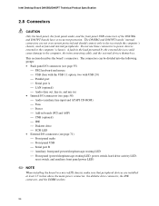
... (optional) IDE Diskette drive SCSI LED • External I/O connectors (see page 71) Front panel audio Front panel USB Serial port B Auxiliary front panel power/sleep/message-waiting LED Front panel (power/sleep/message-waiting LED, power switch, hard drive activity LED, reset switch, and auxiliary front panel power LED) ✏ NOTE When installing the board in the load presented by the external devices could cause damage to the computer's chassis. This section describes the board's connectors. Do not use...
... (optional) IDE Diskette drive SCSI LED • External I/O connectors (see page 71) Front panel audio Front panel USB Serial port B Auxiliary front panel power/sleep/message-waiting LED Front panel (power/sleep/message-waiting LED, power switch, hard drive activity LED, reset switch, and auxiliary front panel power LED) ✏ NOTE When installing the board in the load presented by the external devices could cause damage to the computer's chassis. This section describes the board's connectors. Do not use...

Product Specification
Page 92
... Intel Desktop Board D845BG/D845PT Technical Product Specification 3.2 BIOS Flash Memory Organization The Intel 82802AB Firmware Hub (FWH) includes a 4 Mbit (512 KB) symmetrical flash memory device. Autoconfiguration information is stored in cards. When a user turns on the system after adding a PCI card, the BIOS automatically configures interrupts, the I /O channel support. You can automatically configure PCI devices. If an ATA-66/100 disk drive and a disk drive using slower IDE transfer protocols. To take advantage of the high capacities typically available today, hard drives...
... Intel Desktop Board D845BG/D845PT Technical Product Specification 3.2 BIOS Flash Memory Organization The Intel 82802AB Firmware Hub (FWH) includes a 4 Mbit (512 KB) symmetrical flash memory device. Autoconfiguration information is stored in cards. When a user turns on the system after adding a PCI card, the BIOS automatically configures interrupts, the I /O channel support. You can automatically configure PCI devices. If an ATA-66/100 disk drive and a disk drive using slower IDE transfer protocols. To take advantage of the high capacities typically available today, hard drives...

Product Specification
Page 99
... power supply controls Saves or discards changes to Setup program options For information about Boot Integrity Services (BIS) Refer to view and change the BIOS settings for the computer. The menu bar is accessed by pressing the key after the Power-On Self-Test (POST) memory test begins and before the operating system boot begins. however, the maintenance menu is displayed only when the board is in configuration mode. 99 Maintenance Main Advanced Security Power Boot...
... power supply controls Saves or discards changes to Setup program options For information about Boot Integrity Services (BIS) Refer to view and change the BIOS settings for the computer. The menu bar is accessed by pressing the key after the Power-On Self-Test (POST) memory test begins and before the operating system boot begins. however, the maintenance menu is displayed only when the board is in configuration mode. 99 Maintenance Main Advanced Security Power Boot...

Product Specification
Page 100
...8226; No Extended Configuration • Default (default) • User-Defined CPU Information No options CPU Stepping Signature No options CPU Microcode Update Revision No options Description Clears the user and supervisor passwords. Invokes the Extended Configuration submenu. Intel Desktop Board D845BG/D845PT Technical Product Specification Table 58 lists the function keys available for Management Boot Integrity Service (BIS) credentials. BIOS Setup Program Function Keys BIOS Setup Program Function Key or or Description Selects a different menu screen (Moves the cursor...
...8226; No Extended Configuration • Default (default) • User-Defined CPU Information No options CPU Stepping Signature No options CPU Microcode Update Revision No options Description Clears the user and supervisor passwords. Invokes the Extended Configuration submenu. Intel Desktop Board D845BG/D845PT Technical Product Specification Table 58 lists the function keys available for Management Boot Integrity Service (BIS) credentials. BIOS Setup Program Function Keys BIOS Setup Program Function Key or or Description Selects a different menu screen (Moves the cursor...

Product Specification
Page 101
...8226; Default (default) • User Defined • USWC • UC (default) Description User Defined allows setting memory control and video memory cache mode. Well suited for setting video memory cache mode. Both the video driver and the application must support Write Combining. This setting identifies the video memory range as : "Extended Menu: Used." Table 60. BIOS Setup Program 4.2.1 Extended Configuration Submenu To access this submenu, select Maintenance on the menu bar and then Extended Configuration. Maintenance Main Advanced Security Extended Configuration Power Boot...
...8226; Default (default) • User Defined • USWC • UC (default) Description User Defined allows setting memory control and video memory cache mode. Well suited for setting video memory cache mode. Both the video driver and the application must support Write Combining. This setting identifies the video memory range as : "Extended Menu: Used." Table 60. BIOS Setup Program 4.2.1 Extended Configuration Submenu To access this submenu, select Maintenance on the menu bar and then Extended Configuration. Maintenance Main Advanced Security Extended Configuration Power Boot...
Product Specification
Page 108
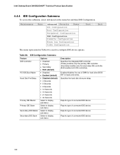
... Desktop Board D845BG/D845PT Technical Product Specification 4.4.4 IDE Configuration Submenu To access this submenu, select Advanced on the menu bar and then IDE Configuration. Table 66. Primary enables only the primary IDE controller. Enables/disables the use of connected IDE device. Reports type of DMA for hard drive BIOS INT13 reads and writes. Reports type of connected IDE device. 108 Reports type of connected IDE device. Reports type of connected IDE device. Specifies the hard disk drive pre-delay. Secondary enables only the secondary IDE controller. Both enables...
... Desktop Board D845BG/D845PT Technical Product Specification 4.4.4 IDE Configuration Submenu To access this submenu, select Advanced on the menu bar and then IDE Configuration. Table 66. Primary enables only the primary IDE controller. Enables/disables the use of connected IDE device. Reports type of DMA for hard drive BIOS INT13 reads and writes. Reports type of connected IDE device. 108 Reports type of connected IDE device. Reports type of connected IDE device. Specifies the hard disk drive pre-delay. Secondary enables only the secondary IDE controller. Both enables...
Product Specification
Page 111
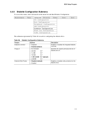
... the capacity and physical size of diskette drive A. Maintenance Main Advanced Security Power PCI Configuration Boot Configuration Peripheral Configuration IDE Configuration Diskette Configuration Event Log Configuration Video Configuration Boot Exit The submenu represented by Table 68 is used for the diskette drive. 111 Disables or enables write protection for configuring the diskette drive. Diskette Configuration Submenu Feature Diskette Controller Floppy A Diskette Write Protect Options • Disabled • Enabled (default) • Not Installed • 360 KB 5¼...
... the capacity and physical size of diskette drive A. Maintenance Main Advanced Security Power PCI Configuration Boot Configuration Peripheral Configuration IDE Configuration Diskette Configuration Event Log Configuration Video Configuration Boot Exit The submenu represented by Table 68 is used for the diskette drive. 111 Disables or enables write protection for configuring the diskette drive. Diskette Configuration Submenu Feature Diskette Controller Floppy A Diskette Write Protect Options • Disabled • Enabled (default) • Not Installed • 360 KB 5¼...

Product Specification
Page 114
... 4) Options No options No options Password can be up to seven alphanumeric characters. Specifies the user password. If both Legacy USB and Unattended Start are set . A password is for user level. Intel Desktop Board D845BG/D845PT Technical Product Specification 4.5 Security Menu To access this menu, select Security from a diskette. This feature appears only if a supervisor password has been set . 2. Maintenance Main Advanced Security Power Boot Exit The menu represented by Table 71 is required to enter a password. 4.
... 4) Options No options No options Password can be up to seven alphanumeric characters. Specifies the user password. If both Legacy USB and Unattended Start are set . A password is for user level. Intel Desktop Board D845BG/D845PT Technical Product Specification 4.5 Security Menu To access this menu, select Security from a diskette. This feature appears only if a supervisor password has been set . 2. Maintenance Main Advanced Security Power Boot Exit The menu represented by Table 71 is required to enter a password. 4.
Product Specification
Page 117
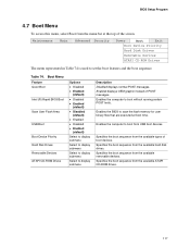
... available removable devices. Enables the BIOS to display submenu Description Disabled displays normal POST messages. Boot Menu Feature Quiet Boot Intel (R) Rapid BIOS Boot Scan User Flash Area USB Boot Boot Device Priority Hard Disk Drives Removable Devices ATAPI CD-ROM Drives Options • Disabled • Enabled (default) • Disabled • Enabled (default) • Disabled (default) • Enabled • Disabled • Enabled (default) Select to display submenu Select to display submenu Select to display submenu Select to scan the flash memory for user binary files that...
... available removable devices. Enables the BIOS to display submenu Description Disabled displays normal POST messages. Boot Menu Feature Quiet Boot Intel (R) Rapid BIOS Boot Scan User Flash Area USB Boot Boot Device Priority Hard Disk Drives Removable Devices ATAPI CD-ROM Drives Options • Disabled • Enabled (default) • Disabled • Enabled (default) • Disabled (default) • Enabled • Disabled • Enabled (default) Select to display submenu Select to display submenu Select to display submenu Select to scan the flash memory for user binary files that...

Product Specification
Page 118
... IDE hard disk drive. Intel Desktop Board D845BG/D845PT Technical Product Specification 4.7.1 Boot Device Priority Submenu To access this menu, select Boot on the BIOS release. 118 Maintenance Main Advanced Security Power Boot Exit Boot Device Priority Hard Disk Drives Removable Devices ATAPI CD-ROM Drives The submenu represented in Table 75 is for Intel Boot Agent (IBA) may vary depending on the menu bar and then Boot Devices Priority. The default settings for the first through fourth boot devices are, respectively: • Removable Dev. • Hard Drive...
... IDE hard disk drive. Intel Desktop Board D845BG/D845PT Technical Product Specification 4.7.1 Boot Device Priority Submenu To access this menu, select Boot on the BIOS release. 118 Maintenance Main Advanced Security Power Boot Exit Boot Device Priority Hard Disk Drives Removable Devices ATAPI CD-ROM Drives The submenu represented in Table 75 is for Intel Boot Agent (IBA) may vary depending on the menu bar and then Boot Devices Priority. The default settings for the first through fourth boot devices are, respectively: • Removable Dev. • Hard Drive...
Product Specification
Page 123
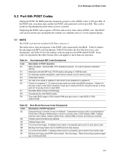
... point where an error occurred. Displaying the POST-codes requires a PCI bus add-in F000 shadow RAM. Retry the booting procedure again (go to boot from floppy. Keyboard controller BAT test, CPU ID saved, and going to I/O port 80h. Table 82. Try to more than one operation. Initialize floppy drive. Error Messages and Beep Codes 5.2 Port 80h POST Codes During the POST, the BIOS generates diagnostic progress codes (POST-codes) to 4 GB flat mode. Booting from floppy failed, look for...
... point where an error occurred. Displaying the POST-codes requires a PCI bus add-in F000 shadow RAM. Retry the booting procedure again (go to boot from floppy. Keyboard controller BAT test, CPU ID saved, and going to I/O port 80h. Table 82. Try to more than one operation. Initialize floppy drive. Error Messages and Beep Codes 5.2 Port 80h POST Codes During the POST, the BIOS generates diagnostic progress codes (POST-codes) to 4 GB flat mode. Booting from floppy failed, look for...

Product Specification
Page 128
... a series of the screen (using both monochrome and color adapters). 128 Table 86. The speaker provides audible error code (beep code) information during POST if the video configuration fails (a faulty video card or no card installed) or if an external ROM module does not properly checksum to initialize the video and writes the error in the upper left corner of short tones. For information about The location of the onboard speaker on...
... a series of the screen (using both monochrome and color adapters). 128 Table 86. The speaker provides audible error code (beep code) information during POST if the video configuration fails (a faulty video card or no card installed) or if an external ROM module does not properly checksum to initialize the video and writes the error in the upper left corner of short tones. For information about The location of the onboard speaker on...


