User Manual
Page 4
...-M User's Manual CONTENTS 1. FEATURES 8 2.1 The ASUS P4T-M 8 2.2 P4T-M Motherboard Components 12 3. HARDWARE SETUP 14 3.1 P4T-M Motherboard Layout 14 3.2 Layout Contents 15 3.3 Getting Started 16 3.4 System Memory 17 3.5.1 CPU Installation 19 3.5 Central Processing Unit (CPU 19 3.5.2 CPU Heatsink Retention Module Installation 20 3.6 Expansion Cards 23 3.6.1 Installing an Expansion Card 23 3.6.2 Assigning IRQs...
...-M User's Manual CONTENTS 1. FEATURES 8 2.1 The ASUS P4T-M 8 2.2 P4T-M Motherboard Components 12 3. HARDWARE SETUP 14 3.1 P4T-M Motherboard Layout 14 3.2 Layout Contents 15 3.3 Getting Started 16 3.4 System Memory 17 3.5.1 CPU Installation 19 3.5 Central Processing Unit (CPU 19 3.5.2 CPU Heatsink Retention Module Installation 20 3.6 Expansion Cards 23 3.6.1 Installing an Expansion Card 23 3.6.2 Assigning IRQs...
User Manual
Page 8
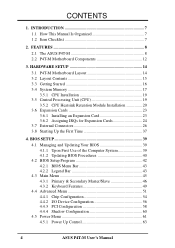
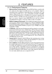
...the demanding PC user who wants advanced features processed by the fastest processors. 2.1.1 Specifications • Intel Processor Support: Intel Socket 423 Pentium® 4 processors. • Intel 850 Chipset: Features the Intel® 850 chipset (Memory Controller Hub, I /O Controller Hub 2 (ICH2) features support for high performance, component level ...for AGP 4X mode; 400MHz Front Side Bus (FSB); 2. All PCI slots can support Bus Master PCI cards, such as SCSI or LAN cards. (PCI supports up to examine and manage system status information, such as DVD-ROM, CD-ROM, CD-R/RW, LS-120, ...
...the demanding PC user who wants advanced features processed by the fastest processors. 2.1.1 Specifications • Intel Processor Support: Intel Socket 423 Pentium® 4 processors. • Intel 850 Chipset: Features the Intel® 850 chipset (Memory Controller Hub, I /O Controller Hub 2 (ICH2) features support for high performance, component level ...for AGP 4X mode; 400MHz Front Side Bus (FSB); 2. All PCI slots can support Bus Master PCI cards, such as SCSI or LAN cards. (PCI supports up to examine and manage system status information, such as DVD-ROM, CD-ROM, CD-R/RW, LS-120, ...
User Manual
Page 9
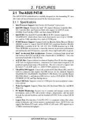
Up to 63 peripheral devices may be directed from PCI master bus to the memory and processor. 2.1.2 Optional Components • Realtek RTL8139C Ethernet: (optional) Single chip fast ethernet controller for 100/10 Mbps data transfer capacity. (See 4.4.2: I /O: Provides two high-...
Up to 63 peripheral devices may be directed from PCI master bus to the memory and processor. 2.1.2 Optional Components • Realtek RTL8139C Ethernet: (optional) Single chip fast ethernet controller for 100/10 Mbps data transfer capacity. (See 4.4.2: I /O: Provides two high-...
User Manual
Page 10
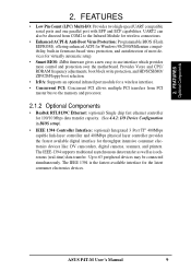
... systems. (UltraDMA/66/100 requires a 40-pin 80-conductor cable to be enabled.) • RDRAM Optimized Performance: This motherboard supports the new generation memory, Rambus Dynamic Random Access Memory (RDRAM). UltraDMA/100 is backward compatible with DMA/66, DMA/33, and DMA and with existing DMA devices and systems so there is...
... systems. (UltraDMA/66/100 requires a 40-pin 80-conductor cable to be enabled.) • RDRAM Optimized Performance: This motherboard supports the new generation memory, Rambus Dynamic Random Access Memory (RDRAM). UltraDMA/100 is backward compatible with DMA/66, DMA/33, and DMA and with existing DMA devices and systems so there is...
User Manual
Page 11
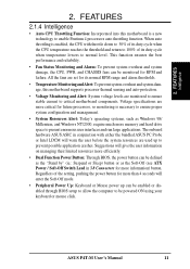
...Suspend or Sleep) button or as Windows 98/ Millenium, and Windows NT/2000, require much more memory and hard drive space to 100% of the setting, pushing the power button for more critical for...future processors, so monitoring is enabled, the CPU with either the bundled ASUS PC Probe or Intel LDCM will give the user information on managing their limited resources more efficiently. • Dual ... management. • System Resources Alert: Today's operating systems, such as the Soft-Off (see ATX Power / Soft-Off Switch Lead in conjunction with throttle down to 50% of its duty cycle when...
...Suspend or Sleep) button or as Windows 98/ Millenium, and Windows NT/2000, require much more memory and hard drive space to 100% of the setting, pushing the power button for more critical for...future processors, so monitoring is enabled, the CPU with either the bundled ASUS PC Probe or Intel LDCM will give the user information on managing their limited resources more efficiently. • Dual ... management. • System Resources Alert: Today's operating systems, such as the Soft-Off (see ATX Power / Soft-Off Switch Lead in conjunction with throttle down to 50% of its duty cycle when...
User Manual
Page 12
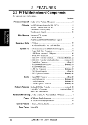
...2.2 P4T-M Motherboard Components See opposite page for Pentium 4 Processors 1 Chipsets Intel 850 Memory Controller Hub (MCH 2 Intel I/O Controller Hub 2 (ICH2 11 4Mbit Firmware Hub (FWH 9 Yamaha Audio Chipset 16 Main Memory Maximum 2GB support 4 RIMM Sockets 3 Dual Channel PC800/PC600 RDRAM support... Bottom) 20 Network Features Realtek LAN Chip Controller optional) 18 LAN (RJ-45) Connector optional) (Top) 25 Wake-On-LAN Connector 15 Hardware Monitoring Low Pin Count (LPC) Winbond Multi-I/O Chipset 4 Power ATX Power Supply Connector 6 ATX 12V Power Supply Connector 6 Special...
...2.2 P4T-M Motherboard Components See opposite page for Pentium 4 Processors 1 Chipsets Intel 850 Memory Controller Hub (MCH 2 Intel I/O Controller Hub 2 (ICH2 11 4Mbit Firmware Hub (FWH 9 Yamaha Audio Chipset 16 Main Memory Maximum 2GB support 4 RIMM Sockets 3 Dual Channel PC800/PC600 RDRAM support... Bottom) 20 Network Features Realtek LAN Chip Controller optional) 18 LAN (RJ-45) Connector optional) (Top) 25 Wake-On-LAN Connector 15 Hardware Monitoring Low Pin Count (LPC) Winbond Multi-I/O Chipset 4 Power ATX Power Supply Connector 6 ATX 12V Power Supply Connector 6 Special...
User Manual
Page 14
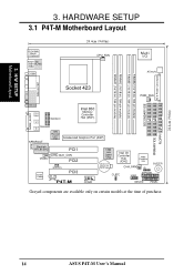
... SETUP 3.1 P4T-M Motherboard Layout PS/2KBMS T: Mouse B: Keyboard Bottom: Top: USB1 RJ-45 USB2 COM1 24.4cm (9.60in) CPU_FAN Multi I/O ATX12V ATX Power Connector PARALLEL PORT Socket 423 PWR_FAN SECONDARY IDE GAME_AUDIO IEEE1394 Line Out Line In 1394HEAD3 Intel 850 Memory Controller Hub (MCH) Mic 1394HEAD2 In 1394 Physical Layer Chip SPDIFOUT Accelerated Graphics...
... SETUP 3.1 P4T-M Motherboard Layout PS/2KBMS T: Mouse B: Keyboard Bottom: Top: USB1 RJ-45 USB2 COM1 24.4cm (9.60in) CPU_FAN Multi I/O ATX12V ATX Power Connector PARALLEL PORT Socket 423 PWR_FAN SECONDARY IDE GAME_AUDIO IEEE1394 Line Out Line In 1394HEAD3 Intel 850 Memory Controller Hub (MCH) Mic 1394HEAD2 In 1394 Physical Layer Chip SPDIFOUT Accelerated Graphics...

User Manual
Page 15
...3) PCI1/2/3 4) AGP 4X p.17 184-Pin System Memory Support p.19 Central Processing Unit (CPU) p.20 CPU... 11) PRIMARY/SECONDARYIDE p.30 Primary/Secondary IDE Connectors (Two 40-1 pin) 12) USB2 p.30 USB Header (10-1 pin) 13) IA p.31 Internal Audio (4 pin SPDIF_OUT...Digital Audio Interface Connector (3 pin WOL) 17) WOLCON p.33 Wake-On-LAN Connector (3 pin) 18) IR p.34 Standard Infrared (SIR) Module Connector (5-pin IR)...p.36 System Management Interrupt Switch Lead (2 pin) 27) PWRSW (PANEL) p.36 ATX Power / Soft-Off Switch Lead (2 pin) 28) RESET (PANEL) p.36 Reset Switch Lead (2...
...3) PCI1/2/3 4) AGP 4X p.17 184-Pin System Memory Support p.19 Central Processing Unit (CPU) p.20 CPU... 11) PRIMARY/SECONDARYIDE p.30 Primary/Secondary IDE Connectors (Two 40-1 pin) 12) USB2 p.30 USB Header (10-1 pin) 13) IA p.31 Internal Audio (4 pin SPDIF_OUT...Digital Audio Interface Connector (3 pin WOL) 17) WOLCON p.33 Wake-On-LAN Connector (3 pin) 18) IR p.34 Standard Infrared (SIR) Module Connector (5-pin IR)...p.36 System Management Interrupt Switch Lead (2 pin) 27) PWRSW (PANEL) p.36 ATX Power / Soft-Off Switch Lead (2 pin) 28) RESET (PANEL) p.36 Reset Switch Lead (2...
User Manual
Page 16
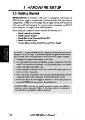
...computer. 1. Unplug your power supply when adding or removing system components. Use a grounded wrist strap before you plug in or remove the ATX power connector on your computer, you work on the motherboard. Hold components by the edges and try not to Pentium 4 CPU's power...static electricity, you should follow some precautions whenever you must complete the following steps: • Check Motherboard Settings • Install Memory Modules • Install the Central Processing Unit (CPU) • Install Expansion Cards • Connect Ribbon Cables, Panel Wires, and Power Supply...
...computer. 1. Unplug your power supply when adding or removing system components. Use a grounded wrist strap before you plug in or remove the ATX power connector on your computer, you work on the motherboard. Hold components by the edges and try not to Pentium 4 CPU's power...static electricity, you should follow some precautions whenever you must complete the following steps: • Check Motherboard Settings • Install Memory Modules • Install the Central Processing Unit (CPU) • Install Expansion Cards • Connect Ribbon Cables, Panel Wires, and Power Supply...

User Manual
Page 17
...B (RIMMB1 and RIMMB2) must be identical (see below). 2. These sockets support 64Mbit, 128Mbit, and 256Mbit Direct RDRAM technologies. The memory configuration of a Rambus interface. 3. C-RIMMs (Continuity RIMM) must be used to avoid breaking the signal lines, which are not populated ..., C-RIMM RIMMA2 it is necessary to complete the sockets that are a serial connection in a Rambus interface, such as used in this motherboard. Location Memory Module Subtotal RIMMA1 (Rows 0&1) RDRAM x 1 C-RIMM (use when socket will not be populated) RIMMA2 (Rows 2&3) RDRAM x 1 C-RIMM (use ...
...B (RIMMB1 and RIMMB2) must be identical (see below). 2. These sockets support 64Mbit, 128Mbit, and 256Mbit Direct RDRAM technologies. The memory configuration of a Rambus interface. 3. C-RIMMs (Continuity RIMM) must be used to avoid breaking the signal lines, which are not populated ..., C-RIMM RIMMA2 it is necessary to complete the sockets that are a serial connection in a Rambus interface, such as used in this motherboard. Location Memory Module Subtotal RIMMA1 (Rows 0&1) RDRAM x 1 C-RIMM (use when socket will not be populated) RIMMA2 (Rows 2&3) RDRAM x 1 C-RIMM (use ...

User Manual
Page 18
...(as shown), push down gently but firmly on the module and the ejectors should go through the two mounting notches on the memory module until it snaps into place. To reduce the risk of the RIMM sockets. IMPORTANT: Do not touch the.... The guides on the socket's ejectors should close. WARNING! 3. HARDWARE SETUP 3.4.1 Installing Memory The memory module (RIMM/C-RIMM) will fit in place. H/W SETUP System Memory P4T-M P4T-M 184-Pin RIMM Sockets 1. Removing Memory To release a memory module, push both ejectors outward and pull the module straight up and out of personal injury...
...(as shown), push down gently but firmly on the module and the ejectors should go through the two mounting notches on the memory module until it snaps into place. To reduce the risk of the RIMM sockets. IMPORTANT: Do not touch the.... The guides on the socket's ejectors should close. WARNING! 3. HARDWARE SETUP 3.4.1 Installing Memory The memory module (RIMM/C-RIMM) will fit in place. H/W SETUP System Memory P4T-M P4T-M 184-Pin RIMM Sockets 1. Removing Memory To release a memory module, push both ejectors outward and pull the module straight up and out of personal injury...
User Manual
Page 25
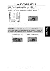
... AGP cards are rated for both types below: An early 3.3V AGP card: Do not use . 3. See examples of AGP graphics cards with ultra-high memory bandwidth. ASUS® AGP 4X cards are supported. Early AGP cards only operate at 3.3 volts and will not fit properly into the new AGP 4X...
... AGP cards are rated for both types below: An early 3.3V AGP card: Do not use . 3. See examples of AGP graphics cards with ultra-high memory bandwidth. ASUS® AGP 4X cards are supported. Early AGP cards only operate at 3.3 volts and will not fit properly into the new AGP 4X...
User Manual
Page 37
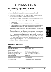
... Meaning No error during POST No DRAM installed or detected Video card not found or video card memory bad CPU overheated System running , the BIOS will alarm beeps or additional messages will then run ...is equipped with the last device on the front panel of the system case will light when the ATX power switch is pressed. The LED on tests. While the tests are running at a lower frequency... need to your system case according to switch on the power supply as well as press the ATX power switch on the front of your system user's manual. 4. Award BIOS Beep Codes Beep ...
... Meaning No error during POST No DRAM installed or detected Video card not found or video card memory bad CPU overheated System running , the BIOS will alarm beeps or additional messages will then run ...is equipped with the last device on the front panel of the system case will light when the ATX power switch is pressed. The LED on tests. While the tests are running at a lower frequency... need to your system case according to switch on the power supply as well as press the ATX power switch on the front of your system user's manual. 4. Award BIOS Beep Codes Beep ...

User Manual
Page 39
...1. DO NOT copy AUTOEXEC.BAT & CONFIG.SYS to run AFLASH. 4. It will not work with DOS prompt in Windows and will not work with a Flash Memory Writer utility (AFLASH.EXE) to a bootable floppy disk in DOS mode. NOTE: BIOS setup must specify "Floppy" as the first item in DOS mode. If... "unknown" is displayed after Flash Memory:, the memory chip is either not programmable or is your hard drive. NOTE: AFLASH works only in the boot sequence. 4. Reboot your computer from your CD-ROM...
...1. DO NOT copy AUTOEXEC.BAT & CONFIG.SYS to run AFLASH. 4. It will not work with DOS prompt in Windows and will not work with a Flash Memory Writer utility (AFLASH.EXE) to a bootable floppy disk in DOS mode. NOTE: BIOS setup must specify "Floppy" as the first item in DOS mode. If... "unknown" is displayed after Flash Memory:, the memory chip is either not programmable or is your hard drive. NOTE: AFLASH works only in the boot sequence. 4. Reboot your computer from your CD-ROM...

User Manual
Page 41
... the new BIOS, DO NOT turn off your system since this happens, your system may not be updated automatically only when necessary. If the Flash Memory Writer utility was not able to disk above. The boot block will prevent your system from booting up . When the programming is finished, Flashed Successfully...
... the new BIOS, DO NOT turn off your system since this happens, your system may not be updated automatically only when necessary. If the Flash Memory Writer utility was not able to disk above. The boot block will prevent your system from booting up . When the programming is finished, Flashed Successfully...

User Manual
Page 50
... CLRTC CLRTC 3 2 2 1 Operational CLEAR CMOS Default Position P4T-M P4T-M Clear RTC RAM Halt On [All but Disk/Keyboard] Installed Memory [XXX MB] This display-only field displays the amount of the BIOS' displayed language. BIOS SETUP Language [English] This allows selection of conventional... memory detected by the onboard button cell battery. When disabled, anyone may access all configuration fields. Press and the password will appear....
... CLRTC CLRTC 3 2 2 1 Operational CLEAR CMOS Default Position P4T-M P4T-M Clear RTC RAM Halt On [All but Disk/Keyboard] Installed Memory [XXX MB] This display-only field displays the amount of the BIOS' displayed language. BIOS SETUP Language [English] This allows selection of conventional... memory detected by the onboard button cell battery. When disabled, anyone may access all configuration fields. Press and the password will appear....
User Manual
Page 51
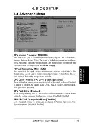
... Frequency (MHz) [Auto] This feature tells the clock generator what frequency to send to select the internal frequency of [Enabled] or choose [Disabled] to the memory. no options are available. CPU Level 1 Cache, CPU Level 2 Cache [Enabled] These fields allow you desire. Leave on default setting for optimized performance of locked...
... Frequency (MHz) [Auto] This feature tells the clock generator what frequency to send to select the internal frequency of [Enabled] or choose [Disabled] to the memory. no options are available. CPU Level 1 Cache, CPU Level 2 Cache [Enabled] These fields allow you desire. Leave on default setting for optimized performance of locked...
User Manual
Page 52
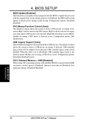
... the default position of [Auto] allows the system to detect a PS/2 mouse on all processors during system bootup. Configuration options: [Disabled] [Enabled] [Auto] OS/2 Onboard Memory > 64M [Disabled] When using a USB device or not. IRQ12 will be disabled. Configuration options: [Disabled] [Enabled] Advanced Menu 4. When this on startup. 4. The default of...
... the default position of [Auto] allows the system to detect a PS/2 mouse on all processors during system bootup. Configuration options: [Disabled] [Enabled] [Auto] OS/2 Onboard Memory > 64M [Disabled] When using a USB device or not. IRQ12 will be disabled. Configuration options: [Disabled] [Enabled] Advanced Menu 4. When this on startup. 4. The default of...

User Manual
Page 54
...in Pool B. You must set this feature; BIOS SETUP Chip Configuration RDRAM Pool B State [Standby] This sets the operating state of mapped memory for the video memory of the processor. otherwise your display card cannot support this to the working state quickly. Configuration options: [UC] [USWC] 54 ASUS P4T...4. It can greatly improve the display speed by caching the display data. Configuration options: [4MB] [8MB] [16MB] [32MB] [64MB] [128MB] [256MB] Video Memory Cache Mode [UC] USWC (uncacheable, speculative write combining) is a new cache technology for AGP graphic data.
...in Pool B. You must set this feature; BIOS SETUP Chip Configuration RDRAM Pool B State [Standby] This sets the operating state of mapped memory for the video memory of the processor. otherwise your display card cannot support this to the working state quickly. Configuration options: [UC] [USWC] 54 ASUS P4T...4. It can greatly improve the display speed by caching the display data. Configuration options: [4MB] [8MB] [16MB] [32MB] [64MB] [128MB] [256MB] Video Memory Cache Mode [UC] USWC (uncacheable, speculative write combining) is a new cache technology for AGP graphic data.
User Manual
Page 55
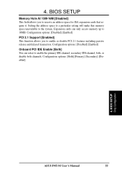
... it. Expansion cards can select to enable the primary IDE channel, secondary IDE channel, both, or disable both channels. BIOS SETUP Memory Hole At 15M-16M [Disabled] This field allows you to the system. 4. Configuration options: [Disabled] [Enabled] Onboard PCI IDE... Enable [Both] You can only access memory up to reserve an address space for ISA expansion cards that memory space unavailable to enable or disable PCI 2.1 features including passive release and delayed transaction. Configuration options: [Both...
... it. Expansion cards can select to enable the primary IDE channel, secondary IDE channel, both, or disable both channels. BIOS SETUP Memory Hole At 15M-16M [Disabled] This field allows you to the system. 4. Configuration options: [Disabled] [Enabled] Onboard PCI IDE... Enable [Both] You can only access memory up to reserve an address space for ISA expansion cards that memory space unavailable to enable or disable PCI 2.1 features including passive release and delayed transaction. Configuration options: [Both...


